EP0370666A1 - Actionneur électromagnétique - Google Patents
Actionneur électromagnétique Download PDFInfo
- Publication number
- EP0370666A1 EP0370666A1 EP89311699A EP89311699A EP0370666A1 EP 0370666 A1 EP0370666 A1 EP 0370666A1 EP 89311699 A EP89311699 A EP 89311699A EP 89311699 A EP89311699 A EP 89311699A EP 0370666 A1 EP0370666 A1 EP 0370666A1
- Authority
- EP
- European Patent Office
- Prior art keywords
- armature
- annular
- bridging member
- electromagnetic actuator
- magnet structure
- Prior art date
- Legal status (The legal status is an assumption and is not a legal conclusion. Google has not performed a legal analysis and makes no representation as to the accuracy of the status listed.)
- Withdrawn
Links
- 238000004804 winding Methods 0.000 claims abstract description 11
- 239000000463 material Substances 0.000 claims abstract description 6
- 238000003475 lamination Methods 0.000 claims abstract description 4
- 230000000295 complement effect Effects 0.000 claims description 4
- 230000002093 peripheral effect Effects 0.000 claims description 4
- 230000004323 axial length Effects 0.000 claims description 3
- 238000004519 manufacturing process Methods 0.000 claims description 2
- 238000005452 bending Methods 0.000 claims 1
- 239000011343 solid material Substances 0.000 claims 1
- 230000004048 modification Effects 0.000 description 6
- 238000012986 modification Methods 0.000 description 6
- 230000008878 coupling Effects 0.000 description 2
- 238000010168 coupling process Methods 0.000 description 2
- 238000005859 coupling reaction Methods 0.000 description 2
- 230000004907 flux Effects 0.000 description 2
- 239000000696 magnetic material Substances 0.000 description 2
- 238000000034 method Methods 0.000 description 2
- 239000000853 adhesive Substances 0.000 description 1
- 230000001070 adhesive effect Effects 0.000 description 1
- 239000004568 cement Substances 0.000 description 1
- 239000011248 coating agent Substances 0.000 description 1
- 238000000576 coating method Methods 0.000 description 1
- 150000001875 compounds Chemical class 0.000 description 1
- 230000003628 erosive effect Effects 0.000 description 1
- 239000012530 fluid Substances 0.000 description 1
- 238000004382 potting Methods 0.000 description 1
- 239000007787 solid Substances 0.000 description 1
Images


Classifications
-
- H—ELECTRICITY
- H01—ELECTRIC ELEMENTS
- H01F—MAGNETS; INDUCTANCES; TRANSFORMERS; SELECTION OF MATERIALS FOR THEIR MAGNETIC PROPERTIES
- H01F7/00—Magnets
- H01F7/06—Electromagnets; Actuators including electromagnets
- H01F7/08—Electromagnets; Actuators including electromagnets with armatures
- H01F7/081—Magnetic constructions
-
- H—ELECTRICITY
- H01—ELECTRIC ELEMENTS
- H01F—MAGNETS; INDUCTANCES; TRANSFORMERS; SELECTION OF MATERIALS FOR THEIR MAGNETIC PROPERTIES
- H01F3/00—Cores, Yokes, or armatures
- H01F3/04—Cores, Yokes, or armatures made from strips or ribbons
-
- H—ELECTRICITY
- H01—ELECTRIC ELEMENTS
- H01F—MAGNETS; INDUCTANCES; TRANSFORMERS; SELECTION OF MATERIALS FOR THEIR MAGNETIC PROPERTIES
- H01F3/00—Cores, Yokes, or armatures
- H01F3/06—Cores, Yokes, or armatures made from wires
-
- H—ELECTRICITY
- H01—ELECTRIC ELEMENTS
- H01F—MAGNETS; INDUCTANCES; TRANSFORMERS; SELECTION OF MATERIALS FOR THEIR MAGNETIC PROPERTIES
- H01F7/00—Magnets
- H01F7/06—Electromagnets; Actuators including electromagnets
- H01F7/08—Electromagnets; Actuators including electromagnets with armatures
Definitions
- This invention relates to an electromagnetic actuator of the kind comprising a magnet structure and an armature, the magnet structure defining at least two pole pieces which when an electrical winding forming part of the magnet structure is energised, assume opposite magnetic polarity, the armature being presented to the pole faces and being attracted to the pole faces when the winding is energised.
- the magnet structure is a stack of laminations of generally "E" shape with the winding located about the centre limb.
- the free end of the centre limb forms one pole face having one polarity when the winding is energised and the outer limbs define pole faces which both assume the opposite polarity.
- the armature is of generally rectangular section.
- the magnet structure so that the centre limb is cylindrical and the outer limbs form part of an annular member, the winding being located about the centre limb.
- Such a magnet structure will have associated with it a circular armature.
- British specification 2201039A discloses such an arrangement as described in the preceding paragraph and also describes a number of ways of constructing the structure in order to minimise the eddy currents.
- the object of the invention is to provide an electromagnetic actuator of the kind specified in a simple and convenient form.
- the magnet structure comprises inner and outer annular members formed from wound strip material and an annular bridging member interconnecting one end of the inner annular member with the adjacent end of the outer annular member.
- the faces of said ends of the inner and outer annular members are chamfered and the inner and outer peripheral surfaces of the bridging member are shaped in a complementary manner.
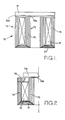
- the actuator comprises a magnet structure 10 and an armature 11.
- the magnet structure includes an annular winding 12 and defines annular pole faces 13A, 14A which when the winding is energised assume opposite magnetic polarity.
- the armature is spaced from the pole faces and the magnetic flux passing between the pole faces and the armature causes an attraction force to be developed between the armature and the magnet structure.
- the pole faces are defined at one end of pole pieces 13, 14 respectively.
- the pole pieces are defined by, inner and outer annular members 15, 16 and the magnet structure further includes an annular bridging member 17 which provides magnetic coupling between the ends of the annular members remote from the armature.
- the members 15, 16 and the bridging member are formed from magnetic material.
- Each of the annular members 15, 16 is formed by winding magnetic strip material about a mandrel, the material preferably being non-grain orientated or grain orientated across its width, adjacent layers of the strip being secured in any convenient manner such for example by adhesive or cement, and the adjacent layers of the strip being electrically insulated from each other by an insulating coating applied to one or both faces of the strip.
- the radial width of the annular member 16 is less than that of the member 15.
- the bridging member 17 comprises a stack of laminations which may be formed from non-grain orientated material and in order to enhance the magnetic coupling between the bridging member and the annular members 15, 16 the inner and outer peripheral edges of the bridging member are chamfered and the adjacent end surfaces of the inner and outer annular members 15, 16 are chamfered in a complementary manner.
- the chamfering may be effected by grinding or by eroding techniques or in any other convenient manner.
- the resultant actuator has a magnetic circuit a substantial part of which is of a laminated nature so that the eddy currents which arise due to changes in the magnetic flux during the use of the actuator, are minimised.
- the actuator is intended specifically to control a valve member of a fluid control valve and a connecting member to the armature can pass through the central opening in the inner annular member if so required.
- the outer annular member 16 is of reduced axial length and an annular pole piece 18 is provided which is magnetically coupled to the end face of the outer member and which extends towards the inner annular member 15.
- the inner face of the pole piece is cut at an angle to reduce magnetic leakage.
- the armature 11A is of reduced diameter and therefore lighter.
- Figure 3 shows a further modification in that the bridging member 17A is constructed as an annular member from solid magnetic material.
- the inner and outer annular members 15A, 16A have flat ends for engagement with the flat surface of the member 17A.
- the modification as described with reference to Figure 2 can be applied to the modified actuator as shown in Figure 3.
- FIG 4 shows a further modification of the example shown in Figure 2 and in this case as in the example of Figure 1, the inner and outer annular members 15, 16 are of the same axial length.
- the annular pole piece 18 is provided as also is an inner annular pole piece 19 which has an integral spigot 20 which is located in the central opening in the inner member 15.
- the spigot 20 is hollow and in the example a portion of the inner surface is provided with a screw thread.
- the thread in use can be engaged by a threaded bolt which can secure the magnet structure to a support.
- the bolt can be hollow to allow the passage therethrough of a connecting member.
- the outer periphery of the pole piece 19 is shaped in a manner complementary to the inner periphery of the pole piece 18.
- An alternative way of constructing a magnet structure is to form the inner and outer annular members and also the bridging member from a plurality of lengths of wire which may be of square or round section. Each length of wire during the process of constructing the magnet structure is bent to "U" shaped form.
- a bundle of wires is assembled about a mandrel and in a central opening in an annular die.
- the wires are then bent radially outwardly and then axially in one or a series of press operations following which the wires are secured, relative to each other by for example a potting compound, before removal from the die.
- the thickness of the bridging member will decrease towards its outer peripheral edge and the outer annular member will be of reduced thickness as compared with the inner annular member, the cross sectional area of the magnetic circuit remaining constant.
Landscapes
- Engineering & Computer Science (AREA)
- Power Engineering (AREA)
- Physics & Mathematics (AREA)
- Electromagnetism (AREA)
- Reciprocating, Oscillating Or Vibrating Motors (AREA)
- Electromagnets (AREA)
Applications Claiming Priority (2)
| Application Number | Priority Date | Filing Date | Title |
|---|---|---|---|
| GB888827108A GB8827108D0 (en) | 1988-11-19 | 1988-11-19 | Electromagnetic actuator |
| GB8827108 | 1988-11-19 |
Publications (1)
| Publication Number | Publication Date |
|---|---|
| EP0370666A1 true EP0370666A1 (fr) | 1990-05-30 |
Family
ID=10647155
Family Applications (1)
| Application Number | Title | Priority Date | Filing Date |
|---|---|---|---|
| EP89311699A Withdrawn EP0370666A1 (fr) | 1988-11-19 | 1989-11-10 | Actionneur électromagnétique |
Country Status (3)
| Country | Link |
|---|---|
| EP (1) | EP0370666A1 (fr) |
| JP (1) | JPH02180006A (fr) |
| GB (1) | GB8827108D0 (fr) |
Cited By (2)
| Publication number | Priority date | Publication date | Assignee | Title |
|---|---|---|---|---|
| EP1022415A1 (fr) * | 1999-01-19 | 2000-07-26 | Aug. Winkhaus GmbH & Co. KG | Dispositif de blocage à actionnement électromagnétique |
| EP1022416A1 (fr) * | 1999-01-19 | 2000-07-26 | Aug. Winkhaus GmbH & Co. KG | Dispositif de blocage à actionnement électromagnétique |
Citations (9)
| Publication number | Priority date | Publication date | Assignee | Title |
|---|---|---|---|---|
| US2648124A (en) * | 1947-08-09 | 1953-08-11 | Duyck Georges | Method of manufacturing electromagnets |
| FR1200567A (fr) * | 1957-07-22 | 1959-12-22 | British Thomson Houston Co Ltd | Perfectionnements apportés aux appareils à induction |
| FR1219327A (fr) * | 1958-12-23 | 1960-05-17 | Acec | Circuits magnétiques pour bobines de self, transformateurs et analogues |
| US3036247A (en) * | 1959-04-23 | 1962-05-22 | Koontz Wagner Electric Company | Electromagnet |
| US3304599A (en) * | 1965-03-30 | 1967-02-21 | Teletype Corp | Method of manufacturing an electromagnet having a u-shaped core |
| DE2014099A1 (de) * | 1970-03-24 | 1971-10-14 | Thomas Fa Robert | Elektromagnet zum Betatigen nachge ordneter Vorrichtungen |
| FR2344109A1 (fr) * | 1976-03-08 | 1977-10-07 | Ungari Serge | Transformateur statique a noyau central |
| GB2046142A (en) * | 1979-03-20 | 1980-11-12 | Aerospatiale | Process for making a magnetic armature and armature thus obtained |
| GB2144060A (en) * | 1983-07-28 | 1985-02-27 | Lucas Ind Plc | Electromagnetic valve assembly |
-
1988
- 1988-11-19 GB GB888827108A patent/GB8827108D0/en active Pending
-
1989
- 1989-11-10 EP EP89311699A patent/EP0370666A1/fr not_active Withdrawn
- 1989-11-20 JP JP30179689A patent/JPH02180006A/ja active Pending
Patent Citations (9)
| Publication number | Priority date | Publication date | Assignee | Title |
|---|---|---|---|---|
| US2648124A (en) * | 1947-08-09 | 1953-08-11 | Duyck Georges | Method of manufacturing electromagnets |
| FR1200567A (fr) * | 1957-07-22 | 1959-12-22 | British Thomson Houston Co Ltd | Perfectionnements apportés aux appareils à induction |
| FR1219327A (fr) * | 1958-12-23 | 1960-05-17 | Acec | Circuits magnétiques pour bobines de self, transformateurs et analogues |
| US3036247A (en) * | 1959-04-23 | 1962-05-22 | Koontz Wagner Electric Company | Electromagnet |
| US3304599A (en) * | 1965-03-30 | 1967-02-21 | Teletype Corp | Method of manufacturing an electromagnet having a u-shaped core |
| DE2014099A1 (de) * | 1970-03-24 | 1971-10-14 | Thomas Fa Robert | Elektromagnet zum Betatigen nachge ordneter Vorrichtungen |
| FR2344109A1 (fr) * | 1976-03-08 | 1977-10-07 | Ungari Serge | Transformateur statique a noyau central |
| GB2046142A (en) * | 1979-03-20 | 1980-11-12 | Aerospatiale | Process for making a magnetic armature and armature thus obtained |
| GB2144060A (en) * | 1983-07-28 | 1985-02-27 | Lucas Ind Plc | Electromagnetic valve assembly |
Non-Patent Citations (1)
| Title |
|---|
| Research Disclosure no. 274, February 1987, HAVANT GB page 58 "Partially Laminated Core Structure" * |
Cited By (2)
| Publication number | Priority date | Publication date | Assignee | Title |
|---|---|---|---|---|
| EP1022415A1 (fr) * | 1999-01-19 | 2000-07-26 | Aug. Winkhaus GmbH & Co. KG | Dispositif de blocage à actionnement électromagnétique |
| EP1022416A1 (fr) * | 1999-01-19 | 2000-07-26 | Aug. Winkhaus GmbH & Co. KG | Dispositif de blocage à actionnement électromagnétique |
Also Published As
| Publication number | Publication date |
|---|---|
| JPH02180006A (ja) | 1990-07-12 |
| GB8827108D0 (en) | 1988-12-21 |
Similar Documents
| Publication | Publication Date | Title |
|---|---|---|
| US4347449A (en) | Process for making a magnetic armature of divided structure and armature thus obtained | |
| KR100359704B1 (ko) | 철심장치 | |
| US5659218A (en) | Motor stator including bobbin wound coils and method of fabrication | |
| US6388549B1 (en) | Magnet core | |
| KR910004932A (ko) | 점화코일(ignition coil) | |
| US4716393A (en) | Electromagnetic actuator | |
| KR100208483B1 (ko) | 원통형 리니어모터 | |
| US5181004A (en) | Solenoid coil assembly | |
| CA2127989A1 (fr) | Actionneur electromagnetique a fil ferromagnetique | |
| WO2004040598A1 (fr) | Dispositif de couplage | |
| EP3560037B1 (fr) | Segment d'antenne et antenne à segments multiples | |
| US6954129B2 (en) | Wire core inductive devices having a flux coupling structure and methods of making the same | |
| US4326139A (en) | Electromagnetic devices | |
| CN1288241A (zh) | 线圈 | |
| US20020105248A1 (en) | Stator structure of reciprocating motor | |
| US6515396B1 (en) | Stator flux ring having fastenable pole pieces and method of making same | |
| CN1049394A (zh) | 点火线圈 | |
| US3036247A (en) | Electromagnet | |
| KR101611855B1 (ko) | 전기모터용 외측 고정자와 전기모터의 제조방법 및 외측 고정자와 동기형 전기모터 | |
| JPH02180006A (ja) | 電磁アクチュエータ及びその製造方法 | |
| GB2105522A (en) | Laminated core structure | |
| EP0862783B1 (fr) | Composant inductif | |
| JPH09322453A (ja) | ステータコア | |
| US20050093671A1 (en) | Inductive devices having a wire core with wires of different shapes and methods of making the same | |
| EP0862782A1 (fr) | Commutateur a fonction de bobine d'inductance |
Legal Events
| Date | Code | Title | Description |
|---|---|---|---|
| PUAI | Public reference made under article 153(3) epc to a published international application that has entered the european phase |
Free format text: ORIGINAL CODE: 0009012 |
|
| AK | Designated contracting states |
Kind code of ref document: A1 Designated state(s): DE FR GB IT |
|
| STAA | Information on the status of an ep patent application or granted ep patent |
Free format text: STATUS: THE APPLICATION IS DEEMED TO BE WITHDRAWN |
|
| 18D | Application deemed to be withdrawn |
Effective date: 19901201 |