EP0370818B1 - Connexion électrique à deux éléments - Google Patents
Connexion électrique à deux éléments Download PDFInfo
- Publication number
- EP0370818B1 EP0370818B1 EP89312195A EP89312195A EP0370818B1 EP 0370818 B1 EP0370818 B1 EP 0370818B1 EP 89312195 A EP89312195 A EP 89312195A EP 89312195 A EP89312195 A EP 89312195A EP 0370818 B1 EP0370818 B1 EP 0370818B1
- Authority
- EP
- European Patent Office
- Prior art keywords
- main frame
- fibers
- machine
- contact
- conductive
- Prior art date
- Legal status (The legal status is an assumption and is not a legal conclusion. Google has not performed a legal analysis and makes no representation as to the accuracy of the status listed.)
- Expired - Lifetime
Links
- 239000000835 fiber Substances 0.000 claims description 97
- 238000012545 processing Methods 0.000 claims description 30
- 229920000642 polymer Polymers 0.000 claims description 18
- 239000011159 matrix material Substances 0.000 claims description 14
- 229920002239 polyacrylonitrile Polymers 0.000 claims description 13
- 238000007639 printing Methods 0.000 claims description 13
- 239000002131 composite material Substances 0.000 claims description 9
- 238000003780 insertion Methods 0.000 claims description 7
- 230000037431 insertion Effects 0.000 claims description 7
- 239000000853 adhesive Substances 0.000 claims description 5
- 230000001070 adhesive effect Effects 0.000 claims description 5
- 239000012212 insulator Substances 0.000 claims 1
- 239000000463 material Substances 0.000 description 17
- 229910052751 metal Inorganic materials 0.000 description 11
- 239000002184 metal Substances 0.000 description 11
- 108091008695 photoreceptors Proteins 0.000 description 11
- 229920000049 Carbon (fiber) Polymers 0.000 description 10
- 239000004917 carbon fiber Substances 0.000 description 10
- 238000012360 testing method Methods 0.000 description 9
- OKTJSMMVPCPJKN-UHFFFAOYSA-N Carbon Chemical compound [C] OKTJSMMVPCPJKN-UHFFFAOYSA-N 0.000 description 8
- 239000002245 particle Substances 0.000 description 8
- 238000012546 transfer Methods 0.000 description 7
- 230000008901 benefit Effects 0.000 description 6
- 229910052799 carbon Inorganic materials 0.000 description 6
- 238000003763 carbonization Methods 0.000 description 6
- 238000004140 cleaning Methods 0.000 description 6
- 238000003384 imaging method Methods 0.000 description 6
- 238000000034 method Methods 0.000 description 6
- 230000032258 transport Effects 0.000 description 6
- 239000004593 Epoxy Substances 0.000 description 5
- 238000007600 charging Methods 0.000 description 5
- 238000011161 development Methods 0.000 description 5
- 239000000843 powder Substances 0.000 description 5
- 239000004744 fabric Substances 0.000 description 4
- 238000004519 manufacturing process Methods 0.000 description 4
- 230000008569 process Effects 0.000 description 4
- 229920005989 resin Polymers 0.000 description 4
- 239000011347 resin Substances 0.000 description 4
- 229910001220 stainless steel Inorganic materials 0.000 description 4
- 239000010935 stainless steel Substances 0.000 description 4
- BQCADISMDOOEFD-UHFFFAOYSA-N Silver Chemical compound [Ag] BQCADISMDOOEFD-UHFFFAOYSA-N 0.000 description 3
- 229910052782 aluminium Inorganic materials 0.000 description 3
- XAGFODPZIPBFFR-UHFFFAOYSA-N aluminium Chemical compound [Al] XAGFODPZIPBFFR-UHFFFAOYSA-N 0.000 description 3
- 238000010438 heat treatment Methods 0.000 description 3
- 239000002243 precursor Substances 0.000 description 3
- 229910052709 silver Inorganic materials 0.000 description 3
- 239000004332 silver Substances 0.000 description 3
- IJGRMHOSHXDMSA-UHFFFAOYSA-N Atomic nitrogen Chemical compound N#N IJGRMHOSHXDMSA-UHFFFAOYSA-N 0.000 description 2
- VTYYLEPIZMXCLO-UHFFFAOYSA-L Calcium carbonate Chemical compound [Ca+2].[O-]C([O-])=O VTYYLEPIZMXCLO-UHFFFAOYSA-L 0.000 description 2
- CURLTUGMZLYLDI-UHFFFAOYSA-N Carbon dioxide Chemical compound O=C=O CURLTUGMZLYLDI-UHFFFAOYSA-N 0.000 description 2
- PXHVJJICTQNCMI-UHFFFAOYSA-N Nickel Chemical compound [Ni] PXHVJJICTQNCMI-UHFFFAOYSA-N 0.000 description 2
- VYPSYNLAJGMNEJ-UHFFFAOYSA-N Silicium dioxide Chemical compound O=[Si]=O VYPSYNLAJGMNEJ-UHFFFAOYSA-N 0.000 description 2
- 229910000831 Steel Inorganic materials 0.000 description 2
- 239000010439 graphite Substances 0.000 description 2
- 229910002804 graphite Inorganic materials 0.000 description 2
- 230000005484 gravity Effects 0.000 description 2
- 238000011068 loading method Methods 0.000 description 2
- 230000005291 magnetic effect Effects 0.000 description 2
- 239000000203 mixture Substances 0.000 description 2
- 230000003287 optical effect Effects 0.000 description 2
- 229920003023 plastic Polymers 0.000 description 2
- 239000004033 plastic Substances 0.000 description 2
- 239000002985 plastic film Substances 0.000 description 2
- 229920000647 polyepoxide Polymers 0.000 description 2
- 229920000728 polyester Polymers 0.000 description 2
- 238000004513 sizing Methods 0.000 description 2
- 239000010959 steel Substances 0.000 description 2
- 238000007514 turning Methods 0.000 description 2
- UGFAIRIUMAVXCW-UHFFFAOYSA-N Carbon monoxide Chemical compound [O+]#[C-] UGFAIRIUMAVXCW-UHFFFAOYSA-N 0.000 description 1
- 229920004546 Hetron™ Polymers 0.000 description 1
- 239000000654 additive Substances 0.000 description 1
- PNEYBMLMFCGWSK-UHFFFAOYSA-N aluminium oxide Inorganic materials [O-2].[O-2].[O-2].[Al+3].[Al+3] PNEYBMLMFCGWSK-UHFFFAOYSA-N 0.000 description 1
- 238000003491 array Methods 0.000 description 1
- QVGXLLKOCUKJST-UHFFFAOYSA-N atomic oxygen Chemical compound [O] QVGXLLKOCUKJST-UHFFFAOYSA-N 0.000 description 1
- 230000005540 biological transmission Effects 0.000 description 1
- 229910000019 calcium carbonate Inorganic materials 0.000 description 1
- 229910002092 carbon dioxide Inorganic materials 0.000 description 1
- 239000001569 carbon dioxide Substances 0.000 description 1
- 229910002091 carbon monoxide Inorganic materials 0.000 description 1
- 238000006243 chemical reaction Methods 0.000 description 1
- 239000003086 colorant Substances 0.000 description 1
- 239000002322 conducting polymer Substances 0.000 description 1
- 229920001940 conductive polymer Polymers 0.000 description 1
- 239000004020 conductor Substances 0.000 description 1
- 238000010276 construction Methods 0.000 description 1
- 239000000356 contaminant Substances 0.000 description 1
- 238000011109 contamination Methods 0.000 description 1
- 238000005260 corrosion Methods 0.000 description 1
- 230000007797 corrosion Effects 0.000 description 1
- 238000002788 crimping Methods 0.000 description 1
- 230000007812 deficiency Effects 0.000 description 1
- 230000000593 degrading effect Effects 0.000 description 1
- 238000007786 electrostatic charging Methods 0.000 description 1
- 230000003028 elevating effect Effects 0.000 description 1
- 238000005516 engineering process Methods 0.000 description 1
- 125000003700 epoxy group Chemical group 0.000 description 1
- 239000003822 epoxy resin Substances 0.000 description 1
- 230000005294 ferromagnetic effect Effects 0.000 description 1
- 239000002657 fibrous material Substances 0.000 description 1
- 239000000945 filler Substances 0.000 description 1
- 239000005357 flat glass Substances 0.000 description 1
- 229920005560 fluorosilicone rubber Polymers 0.000 description 1
- 239000007789 gas Substances 0.000 description 1
- 239000003365 glass fiber Substances 0.000 description 1
- PCHJSUWPFVWCPO-UHFFFAOYSA-N gold Chemical compound [Au] PCHJSUWPFVWCPO-UHFFFAOYSA-N 0.000 description 1
- 229910052737 gold Inorganic materials 0.000 description 1
- 239000010931 gold Substances 0.000 description 1
- 239000008187 granular material Substances 0.000 description 1
- 238000005304 joining Methods 0.000 description 1
- 239000007788 liquid Substances 0.000 description 1
- 238000003754 machining Methods 0.000 description 1
- 238000012423 maintenance Methods 0.000 description 1
- 230000007246 mechanism Effects 0.000 description 1
- 150000002739 metals Chemical class 0.000 description 1
- 229910052759 nickel Inorganic materials 0.000 description 1
- 229910052757 nitrogen Inorganic materials 0.000 description 1
- 230000003647 oxidation Effects 0.000 description 1
- 238000007254 oxidation reaction Methods 0.000 description 1
- 239000001301 oxygen Substances 0.000 description 1
- 229910052760 oxygen Inorganic materials 0.000 description 1
- 239000000049 pigment Substances 0.000 description 1
- 229920003225 polyurethane elastomer Polymers 0.000 description 1
- 238000002360 preparation method Methods 0.000 description 1
- 238000009877 rendering Methods 0.000 description 1
- 239000000377 silicon dioxide Substances 0.000 description 1
- 229920002379 silicone rubber Polymers 0.000 description 1
- 230000000087 stabilizing effect Effects 0.000 description 1
- 230000003068 static effect Effects 0.000 description 1
- 239000000126 substance Substances 0.000 description 1
- 230000001360 synchronised effect Effects 0.000 description 1
- 229920001169 thermoplastic Polymers 0.000 description 1
- 229920001187 thermosetting polymer Polymers 0.000 description 1
- 239000004416 thermosoftening plastic Substances 0.000 description 1
- 230000005641 tunneling Effects 0.000 description 1
- 229920001567 vinyl ester resin Polymers 0.000 description 1
- 125000000391 vinyl group Chemical group [H]C([*])=C([H])[H] 0.000 description 1
Images



Classifications
-
- G—PHYSICS
- G03—PHOTOGRAPHY; CINEMATOGRAPHY; ANALOGOUS TECHNIQUES USING WAVES OTHER THAN OPTICAL WAVES; ELECTROGRAPHY; HOLOGRAPHY
- G03G—ELECTROGRAPHY; ELECTROPHOTOGRAPHY; MAGNETOGRAPHY
- G03G21/00—Arrangements not provided for by groups G03G13/00 - G03G19/00, e.g. cleaning, elimination of residual charge
- G03G21/16—Mechanical means for facilitating the maintenance of the apparatus, e.g. modular arrangements
- G03G21/18—Mechanical means for facilitating the maintenance of the apparatus, e.g. modular arrangements using a processing cartridge, whereby the process cartridge comprises at least two image processing means in a single unit
- G03G21/1839—Means for handling the process cartridge in the apparatus body
- G03G21/1867—Means for handling the process cartridge in the apparatus body for electrically connecting the process cartridge to the apparatus, electrical connectors, power supply
-
- G—PHYSICS
- G03—PHOTOGRAPHY; CINEMATOGRAPHY; ANALOGOUS TECHNIQUES USING WAVES OTHER THAN OPTICAL WAVES; ELECTROGRAPHY; HOLOGRAPHY
- G03G—ELECTROGRAPHY; ELECTROPHOTOGRAPHY; MAGNETOGRAPHY
- G03G15/00—Apparatus for electrographic processes using a charge pattern
- G03G15/80—Details relating to power supplies, circuits boards, electrical connections
-
- H—ELECTRICITY
- H01—ELECTRIC ELEMENTS
- H01R—ELECTRICALLY-CONDUCTIVE CONNECTIONS; STRUCTURAL ASSOCIATIONS OF A PLURALITY OF MUTUALLY-INSULATED ELECTRICAL CONNECTING ELEMENTS; COUPLING DEVICES; CURRENT COLLECTORS
- H01R39/00—Rotary current collectors, distributors or interrupters
- H01R39/02—Details for dynamo electric machines
- H01R39/18—Contacts for co-operation with commutator or slip-ring, e.g. contact brush
- H01R39/24—Laminated contacts; Wire contacts, e.g. metallic brush, carbon fibres
-
- H—ELECTRICITY
- H01—ELECTRIC ELEMENTS
- H01R—ELECTRICALLY-CONDUCTIVE CONNECTIONS; STRUCTURAL ASSOCIATIONS OF A PLURALITY OF MUTUALLY-INSULATED ELECTRICAL CONNECTING ELEMENTS; COUPLING DEVICES; CURRENT COLLECTORS
- H01R41/00—Non-rotary current collectors for maintaining contact between moving and stationary parts of an electric circuit
-
- G—PHYSICS
- G03—PHOTOGRAPHY; CINEMATOGRAPHY; ANALOGOUS TECHNIQUES USING WAVES OTHER THAN OPTICAL WAVES; ELECTROGRAPHY; HOLOGRAPHY
- G03G—ELECTROGRAPHY; ELECTROPHOTOGRAPHY; MAGNETOGRAPHY
- G03G2221/00—Processes not provided for by group G03G2215/00, e.g. cleaning or residual charge elimination
- G03G2221/16—Mechanical means for facilitating the maintenance of the apparatus, e.g. modular arrangements and complete machine concepts
- G03G2221/1651—Mechanical means for facilitating the maintenance of the apparatus, e.g. modular arrangements and complete machine concepts for connecting the different parts
-
- G—PHYSICS
- G03—PHOTOGRAPHY; CINEMATOGRAPHY; ANALOGOUS TECHNIQUES USING WAVES OTHER THAN OPTICAL WAVES; ELECTROGRAPHY; HOLOGRAPHY
- G03G—ELECTROGRAPHY; ELECTROPHOTOGRAPHY; MAGNETOGRAPHY
- G03G2221/00—Processes not provided for by group G03G2215/00, e.g. cleaning or residual charge elimination
- G03G2221/16—Mechanical means for facilitating the maintenance of the apparatus, e.g. modular arrangements and complete machine concepts
- G03G2221/1651—Mechanical means for facilitating the maintenance of the apparatus, e.g. modular arrangements and complete machine concepts for connecting the different parts
- G03G2221/166—Electrical connectors
-
- G—PHYSICS
- G03—PHOTOGRAPHY; CINEMATOGRAPHY; ANALOGOUS TECHNIQUES USING WAVES OTHER THAN OPTICAL WAVES; ELECTROGRAPHY; HOLOGRAPHY
- G03G—ELECTROGRAPHY; ELECTROPHOTOGRAPHY; MAGNETOGRAPHY
- G03G2221/00—Processes not provided for by group G03G2215/00, e.g. cleaning or residual charge elimination
- G03G2221/16—Mechanical means for facilitating the maintenance of the apparatus, e.g. modular arrangements and complete machine concepts
- G03G2221/1669—Details about used materials
-
- G—PHYSICS
- G03—PHOTOGRAPHY; CINEMATOGRAPHY; ANALOGOUS TECHNIQUES USING WAVES OTHER THAN OPTICAL WAVES; ELECTROGRAPHY; HOLOGRAPHY
- G03G—ELECTROGRAPHY; ELECTROPHOTOGRAPHY; MAGNETOGRAPHY
- G03G2221/00—Processes not provided for by group G03G2215/00, e.g. cleaning or residual charge elimination
- G03G2221/16—Mechanical means for facilitating the maintenance of the apparatus, e.g. modular arrangements and complete machine concepts
- G03G2221/18—Cartridge systems
- G03G2221/183—Process cartridge
Definitions
- Most development systems employ developer which comprises both charged carrier particles and charged toner particles which triboelectrically adhere to the carrier particles.
- the toner particles are attracted from the carrier particles by the charged pattern of the image areas of the photoconductive insulating area to form a powder image on the photoconductive area.
- This toner image may be subsequently transferred to a support surface such as copy paper to which it may be permanently affixed by heating or by the application of pressure.
- the sheet 16 (which may be paper, plastic, etc., as desired) is separated from the belt by the beam strength of the sheet material and the sheet with the toner image thereon is advanced to a suitable fuser such as roll fuser 24 which fixes the transferred powder image thereto. After the fusing process the sheet 16 is advanced to a suitable output device such as tray 25.
- Both ends of the belt transport roll have end caps 45 positioned thereon with one end being connected through drive gear 46 to the main machine drive to provide positive drive to the belt.
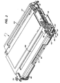
- Mounted adjacent to the mounting pins 40 on both sides of the cartridge are mounting hinge slots 42.
- At the other end of the cartridge assembly is an idler roll shaft 53 about which the idler roll 54 is mounted, once again with end caps at each end thereof.
- the photoreceptor belt 12 is transported around transport roll 43 and idler roll 54 through the various processing stations in the two-cycle reproducing apparatus.
- Exposure slot 49 permits exposure of the photoreceptor belt from the optical system of the reproducing apparatus.
- the brush-like member that constitutes the first element in the electrical connection may be one end of a pultruded member as described hereinafter which has had the polymer matrix removed at one end to expose the individual fibers.
- a pultruded member as described hereinafter which has had the polymer matrix removed at one end to expose the individual fibers.
- the removable unit of the printing machine described above comprises a photoreceptor and a precharge corotron, it will be understood that other processing units may form part of the removable unit.
- the removable unit includes (in addition to the photoreceptor belt) the developer housing.
Landscapes
- Physics & Mathematics (AREA)
- General Physics & Mathematics (AREA)
- Engineering & Computer Science (AREA)
- Computer Vision & Pattern Recognition (AREA)
- Electrophotography Configuration And Component (AREA)
- Motor Or Generator Current Collectors (AREA)
- Electrostatic Charge, Transfer And Separation In Electrography (AREA)
- Control Or Security For Electrophotography (AREA)
- Accessory Devices And Overall Control Thereof (AREA)
Claims (12)
- Machine à imprimer comprenant un châssis principal (10), au moins une unité de traitement (11) insérable et. amovible dudit châssis principal pour une association fonctionnelle avec celui-ci, ladite unité comportant au moins un composant de traitement qui est utilisé en association fonctionnelle avec les composants sur le châssis principal de la machine afin de produire des épreuves, et deux éléments de contact électrique, un sur ledit châssis principal et l'autre sur ladite unité amovible, l'élément de contact sur l'unité amovible étant disposé pour entrer en engagement avec l'élément de contact sur le châssis principal, lorsque l'unité amovible est insérée dans le châssis principal, afin d'établir une connexion électrique pour conduire le courant électrique entre le châssis principal et l'unité amovible, un des éléments de contact comprenant une multitude de fibres de polyacrylonitrile carboné conductrices élastiquement souples (69), disposées en une configuration de type brosse (67) et l'autre élément de contact comprenant une surface conductrice (72) pour le contact électrique avec ladite brosse.
- Machine selon la revendication 1, comportant un porte-support (68) pour lesdites fibres afin de les supporter de sorte qu'elles s'étendent généralement parallèles les unes aux autres et de sorte que les extrémités distales des fibres soient positionnées pour un contact électrique avec ladite surface de contact.
- Machine selon la revendication 2, comportant un adhésif conducteur pour maintenir lesdites fibres dans ledit porte-support.
- Machine selon la revendication 2 ou la revendication 3, dans laquelle ledit porte-support est une borne électrique (68) qui est sertie à un fil électriquement conducteur.
- Machine selon l'une quelconque des revendications précédentes, dans laquelle lesdites fibres présentent un diamètre situé entre environ 5 micromètres et environ 50 micromètres.
- Machine selon l'une quelconque des revendications précédentes, dans laquelle lesdites fibres présentent une résistivité électrique située entre environ 10⁻⁵ et environ 10⁶ ohm cm.
- Machine selon l'une quelconque des revendications précédentes, dans laquelle ladite surface conductrice est un motif conducteur sur un isolant.
- Machine selon l'une quelconque des revendications précédentes, dans laquelle ladite surface conductrice est une surface d'un élément composite extrudé comprenant une multitude de fibres conductrices dans une matrice de polymère, ladite multitude des fibres étant orientée dans ladite matrice dans une direction pratiquement parallèle à la direction axiale dudit élément et étant continue à partir d'une extrémité dudit élément à l'autre extrémité afin de procurer une multitude de contacts potentiels électriques à chaque extrémité dudit élément.
- Machine à imprimer comprenant un châssis principal (10), au moins une unité de traitement (11) insérable et amovible dudit châssis principal pour une association fonctionnelle avec celui-ci, ladite unité comportant au moins un composant de traitement qui est utilisé en association fonctionnelle avec les composants sur le châssis principal de la machine afin de produire des impression et deux éléments de contact électrique, un sur ledit châssis principal et l'autre sur ladite unité amovible, l'élément de contact sur l'unité amovible étant prévu pour entrer en engagement avec l'élément de contact sur le châssis principal, lorsque l'unité amovible est insérée dans le châssis principal, afin d'établir une connexion électrique pour conduire le courant électrique entre le châssis principal et l'unité amovible, un des éléments de contact comprenant une multitude de fibres de conductrices élastiquement souples (69), disposées suivant une configuration de type brosse (67) et l'autre élément de contact comprenant un élément composite extrudé qui procure une surface conductrice (72) pour le contact électrique avec ladite brosse, l'élément composite extrudé comprenant une multitude de fibres conductrices dans une matrice de polymère, les fibres étant orientées dans une direction pratiquement parallèle à l'axe de l'élément extrudé et étant en continu à partir d'une extrémité de l'élément à l'autre extrémité afin de procurer une multitude de contacts potentiels électrique à chaque extrémité de l'élément.
- Machine selon l'une quelconque des revendications précédentes, dans laquelle la surface de contact d'un desdits éléments de contact est nettement supérieure à la surface de contact de l'autre desdits éléments de contact.
- Machine selon l'une quelconque des revendications précédentes, dans laquelle ladite connexion électrique entre lesdits éléments de contact est établie dans une direction parallèle à la direction d'insertion de ladite unité dans ledit châssis principal (figure 3).
- Machine selon l'une quelconque des revendications 1 à 9, dans laquelle ladite connexion électrique entre lesdits éléments de contact est établie dans une direction perpendiculaire à la direction d'insertion de ladite unité dans ledit châssis principal (figure 5).
Applications Claiming Priority (2)
| Application Number | Priority Date | Filing Date | Title |
|---|---|---|---|
| US07/276,835 US5177529A (en) | 1988-11-25 | 1988-11-25 | Machine with removable unit having two element electrical connection |
| US276835 | 1988-11-25 |
Publications (3)
| Publication Number | Publication Date |
|---|---|
| EP0370818A2 EP0370818A2 (fr) | 1990-05-30 |
| EP0370818A3 EP0370818A3 (fr) | 1991-07-17 |
| EP0370818B1 true EP0370818B1 (fr) | 1995-05-10 |
Family
ID=23058250
Family Applications (1)
| Application Number | Title | Priority Date | Filing Date |
|---|---|---|---|
| EP89312195A Expired - Lifetime EP0370818B1 (fr) | 1988-11-25 | 1989-11-23 | Connexion électrique à deux éléments |
Country Status (4)
| Country | Link |
|---|---|
| US (1) | US5177529A (fr) |
| EP (1) | EP0370818B1 (fr) |
| JP (1) | JPH02187774A (fr) |
| DE (1) | DE68922585T2 (fr) |
Families Citing this family (28)
| Publication number | Priority date | Publication date | Assignee | Title |
|---|---|---|---|---|
| FR2679708A1 (fr) * | 1991-07-24 | 1993-01-29 | Schlumberger Ind Sa | Balai de mise au meme potentiel electrique d'un rotor et d'un stator. |
| US5250756A (en) * | 1991-11-21 | 1993-10-05 | Xerox Corporation | Pultruded conductive plastic connector and manufacturing method employing laser processing |
| JP3342906B2 (ja) * | 1991-12-18 | 2002-11-11 | ゼロックス・コーポレーション | 電子装置及び電子スイッチ |
| JP3320102B2 (ja) * | 1992-06-30 | 2002-09-03 | キヤノン株式会社 | プロセスカートリッジ及び画像形成装置 |
| JP2751133B2 (ja) * | 1993-02-26 | 1998-05-18 | 富士通株式会社 | 電子写真式画像形成装置 |
| US5410386A (en) * | 1993-06-25 | 1995-04-25 | Xerox Corporation | Hollow pultruded electical contact |
| US5414216A (en) * | 1993-10-12 | 1995-05-09 | Xerox Corporation | Electrostatographic reproducing machine resistive carbon fiber wire |
| JP3869868B2 (ja) * | 1994-04-27 | 2007-01-17 | キヤノン株式会社 | プロセスカートリッジ及び画像形成装置 |
| AU3426895A (en) | 1994-10-17 | 1996-05-02 | Canon Kabushiki Kaisha | Toner container, toner container assembling method, process cartridge, and electrophotographic image forming apparatus |
| US5473414A (en) * | 1994-12-19 | 1995-12-05 | Xerox Corporation | Cleaning commutator brushes for an electroded donor roll |
| US5510884A (en) * | 1995-03-24 | 1996-04-23 | Xerox Corporation | Supply accessory for a printing machine with hidden identifier |
| US5812908A (en) * | 1997-03-25 | 1998-09-22 | Xerox Corporation | Carbon fiber electrical contact mounting for rotating elements |
| US5794100A (en) * | 1997-03-25 | 1998-08-11 | Xerox Corporation | Carbon fiber electrical contact for rotating elements |
| JP3332813B2 (ja) * | 1997-08-01 | 2002-10-07 | キヤノン株式会社 | プロセスカートリッジ及び電子写真画像形成装置 |
| US5887225A (en) * | 1998-01-05 | 1999-03-23 | Xerox Corporation | Solid carbon fiber electrical rod developer bias contacting method |
| US6140907A (en) * | 1998-08-20 | 2000-10-31 | Cts Corporation | Carbon fiber contacting position sensor |
| US6289187B1 (en) * | 1999-02-04 | 2001-09-11 | Xerox Corporation | Carbon fiber commutator brush for a toner developing device and method for making |
| WO2001048561A1 (fr) * | 1999-12-28 | 2001-07-05 | Toshiba Tec Kabushiki Kaisha | Appareil de fixation |
| US8398413B2 (en) | 2000-02-07 | 2013-03-19 | Micro Contacts, Inc. | Carbon fiber electrical contacts formed of composite material including plural carbon fiber elements bonded together in low-resistance synthetic resin |
| US8029296B2 (en) * | 2000-02-07 | 2011-10-04 | Micro Contacts, Inc. | Carbon fiber electrical contacts formed of composite carbon fiber material |
| US6444102B1 (en) * | 2000-02-07 | 2002-09-03 | Micro Contacts Inc. | Carbon fiber electrical contacts |
| JP3697168B2 (ja) | 2001-03-09 | 2005-09-21 | キヤノン株式会社 | プロセスカートリッジおよび電子写真画像形成装置 |
| JP4035516B2 (ja) | 2004-02-27 | 2008-01-23 | キヤノン株式会社 | 電子写真画像形成装置 |
| GB2425294A (en) * | 2005-04-20 | 2006-10-25 | Clayton Comm Ltd | Trolley battery charging arrangement |
| DE102011053979B4 (de) * | 2011-09-27 | 2017-12-28 | Walter Maschinenbau Gmbh | Schleifkontakteinrichtung einer Erodiereinrichtung einer kombinierten Schleif- und Erodiermaschine und Verfahren zur Herstellung einer Schleifkontakteinrichtung |
| CN102868079B (zh) * | 2012-09-13 | 2014-08-20 | 安徽吉思勘仪器科技有限公司 | 一种用于地震传感器阵列装置的履带滑动电连接结构 |
| CN103066473B (zh) * | 2012-12-29 | 2015-07-15 | 安徽吉思勘仪器科技有限公司 | 一种用于地震传感器阵列装置的履带滑动电连接结构 |
| US10418145B2 (en) * | 2014-06-06 | 2019-09-17 | President And Fellows Of Harvard College | Stretchable conductive composites for use in soft devices |
Citations (2)
| Publication number | Priority date | Publication date | Assignee | Title |
|---|---|---|---|---|
| EP0277312A1 (fr) * | 1987-01-07 | 1988-08-10 | Kurt Hesse | Frotteur pour véhicule jouet à moteur électrique |
| EP0369772A2 (fr) * | 1988-11-17 | 1990-05-23 | Xerox Corporation | Dispositif de conduction du courant électrique |
Family Cites Families (24)
| Publication number | Priority date | Publication date | Assignee | Title |
|---|---|---|---|---|
| US3324445A (en) * | 1964-04-13 | 1967-06-06 | Jack V Miller | Electrical connectors |
| FR1500642A (fr) * | 1966-11-14 | 1967-11-03 | Philips Nv | Balai appelé à établir un contact glissant |
| US3757164A (en) * | 1970-07-17 | 1973-09-04 | Minnesota Mining & Mfg | Neutralizing device |
| US3668451A (en) * | 1970-08-14 | 1972-06-06 | Ian Roderick Mcnab | Electrical brush structure |
| US4074924A (en) * | 1976-10-29 | 1978-02-21 | Lebecque Maurice G N G | Electrical contact system |
| DE2817371C2 (de) * | 1978-04-20 | 1982-08-12 | Siemens AG, 1000 Berlin und 8000 München | Stromübertragungsbürste |
| DE2817317A1 (de) * | 1978-04-20 | 1979-10-25 | Siemens Ag | Stromuebertragungsbuerste |
| DE2944065A1 (de) * | 1979-10-31 | 1981-05-14 | Siemens AG, 1000 Berlin und 8000 München | Stromuebertragungsbuerste mit graphitfolien |
| US4337407A (en) * | 1980-04-29 | 1982-06-29 | Westinghouse Electric Corp. | Insulated strand brushes |
| US4358699A (en) * | 1980-06-05 | 1982-11-09 | The University Of Virginia Alumni Patents Foundation | Versatile electrical fiber brush and method of making |
| US4336565A (en) * | 1980-08-04 | 1982-06-22 | Xerox Corporation | Charge process with a carbon fiber brush electrode |
| JPS5740874A (en) * | 1980-08-22 | 1982-03-06 | Shinetsu Polymer Co | Pressure contact holding type connector |
| JPS57185448A (en) * | 1981-05-11 | 1982-11-15 | Ricoh Co Ltd | Forming method of conductive path |
| US4591258A (en) * | 1981-12-22 | 1986-05-27 | Canon Kabushiki Kaisha | Safety means for process kit |
| US4553191A (en) * | 1982-12-03 | 1985-11-12 | Xerox Corporation | Static eliminator |
| JPS6049357A (ja) * | 1983-08-29 | 1985-03-18 | Ricoh Co Ltd | 光導電性の感光体の感度補正方法 |
| EP0136902B1 (fr) * | 1983-09-30 | 1990-01-31 | Mita Industrial Co. Ltd. | Dispositif électrophotographique comprenant une couche photosemsible composée d'un photoconducteur à silicium amorphe |
| US4561763A (en) * | 1984-08-03 | 1985-12-31 | Xerox Corporation | Drum support apparatus |
| US4761709A (en) * | 1984-10-29 | 1988-08-02 | Xerox Corporation | Contact brush charging |
| US4641949A (en) * | 1985-08-26 | 1987-02-10 | Xerox Corporation | Conductive brush paper position sensor |
| US4706320A (en) * | 1985-12-04 | 1987-11-17 | Xerox Corporation | Electrostatic charging and cleaning brushes |
| US4741942A (en) * | 1985-12-04 | 1988-05-03 | Xerox Corporation | Electrostatic charging and cleaning brushes |
| JPS62239175A (ja) * | 1986-04-11 | 1987-10-20 | Konika Corp | 画像形成装置 |
| US4774389A (en) * | 1986-12-02 | 1988-09-27 | Spivey Lewis A | Intrusion detector switch system with wire bristle switch controls |
-
1988
- 1988-11-25 US US07/276,835 patent/US5177529A/en not_active Expired - Lifetime
-
1989
- 1989-11-21 JP JP1304557A patent/JPH02187774A/ja active Pending
- 1989-11-23 EP EP89312195A patent/EP0370818B1/fr not_active Expired - Lifetime
- 1989-11-23 DE DE68922585T patent/DE68922585T2/de not_active Expired - Lifetime
Patent Citations (2)
| Publication number | Priority date | Publication date | Assignee | Title |
|---|---|---|---|---|
| EP0277312A1 (fr) * | 1987-01-07 | 1988-08-10 | Kurt Hesse | Frotteur pour véhicule jouet à moteur électrique |
| EP0369772A2 (fr) * | 1988-11-17 | 1990-05-23 | Xerox Corporation | Dispositif de conduction du courant électrique |
Also Published As
| Publication number | Publication date |
|---|---|
| JPH02187774A (ja) | 1990-07-23 |
| DE68922585T2 (de) | 1996-01-11 |
| EP0370818A2 (fr) | 1990-05-30 |
| DE68922585D1 (de) | 1995-06-14 |
| EP0370818A3 (fr) | 1991-07-17 |
| US5177529A (en) | 1993-01-05 |
Similar Documents
| Publication | Publication Date | Title |
|---|---|---|
| EP0370818B1 (fr) | Connexion électrique à deux éléments | |
| US5139862A (en) | Pultruded electronic device | |
| US5354607A (en) | Fibrillated pultruded electronic components and static eliminator devices | |
| EP0453143B1 (fr) | Composant électrique fibrillé et pultrudé | |
| EP0411852B1 (fr) | Dispositif de fixage | |
| US4761709A (en) | Contact brush charging | |
| EP0400563B1 (fr) | Appareil d'enregistrement | |
| CA1213313A (fr) | Dispositif de suppression d'electricite statique | |
| US6064841A (en) | Power supply for a charging apparatus having a contact charger for charging an object to be charged | |
| JPH0273264A (ja) | 画像形成装置 | |
| US5220481A (en) | Composite to enable contact electrostatic voltage sensing | |
| JP3647896B2 (ja) | 導電性接点及び静電複写機 | |
| JPS6223073A (ja) | 色選択装置 | |
| EP0369772B1 (fr) | Dispositif de conduction du courant électrique | |
| EP1269268B1 (fr) | Moyeu d'entrainement conducteur | |
| EP0507055B1 (fr) | Appareil de formation d'images | |
| KR950011879B1 (ko) | 화상형성장치 | |
| US4771360A (en) | Grounding brush | |
| US5887225A (en) | Solid carbon fiber electrical rod developer bias contacting method | |
| US4497570A (en) | Printing machine employing an operator replaceable interposition web and photoconductive member | |
| JPH10307440A (ja) | 電荷移動装置および印刷機 | |
| JP2738606B2 (ja) | 電子写真装置 | |
| US5633700A (en) | Actuator for actuating a surface contacting probe of a contacting electrostatic voltmeter | |
| US4423951A (en) | Roller transfer corona apparatus | |
| JPH0675221B2 (ja) | 接触ブラシ帯電装置 |
Legal Events
| Date | Code | Title | Description |
|---|---|---|---|
| PUAI | Public reference made under article 153(3) epc to a published international application that has entered the european phase |
Free format text: ORIGINAL CODE: 0009012 |
|
| AK | Designated contracting states |
Kind code of ref document: A2 Designated state(s): DE FR GB |
|
| PUAL | Search report despatched |
Free format text: ORIGINAL CODE: 0009013 |
|
| AK | Designated contracting states |
Kind code of ref document: A3 Designated state(s): DE FR GB |
|
| 17P | Request for examination filed |
Effective date: 19920109 |
|
| 17Q | First examination report despatched |
Effective date: 19930311 |
|
| GRAA | (expected) grant |
Free format text: ORIGINAL CODE: 0009210 |
|
| AK | Designated contracting states |
Kind code of ref document: B1 Designated state(s): DE FR GB |
|
| REF | Corresponds to: |
Ref document number: 68922585 Country of ref document: DE Date of ref document: 19950614 |
|
| ET | Fr: translation filed | ||
| PLBE | No opposition filed within time limit |
Free format text: ORIGINAL CODE: 0009261 |
|
| STAA | Information on the status of an ep patent application or granted ep patent |
Free format text: STATUS: NO OPPOSITION FILED WITHIN TIME LIMIT |
|
| 26N | No opposition filed | ||
| REG | Reference to a national code |
Ref country code: GB Ref legal event code: IF02 |
|
| PGFP | Annual fee paid to national office [announced via postgrant information from national office to epo] |
Ref country code: DE Payment date: 20081120 Year of fee payment: 20 |
|
| PGFP | Annual fee paid to national office [announced via postgrant information from national office to epo] |
Ref country code: FR Payment date: 20081112 Year of fee payment: 20 |
|
| PGFP | Annual fee paid to national office [announced via postgrant information from national office to epo] |
Ref country code: GB Payment date: 20081119 Year of fee payment: 20 |
|
| REG | Reference to a national code |
Ref country code: GB Ref legal event code: PE20 Expiry date: 20091122 |
|
| PG25 | Lapsed in a contracting state [announced via postgrant information from national office to epo] |
Ref country code: GB Free format text: LAPSE BECAUSE OF EXPIRATION OF PROTECTION Effective date: 20091122 |