EP0370841B1 - Ultraschallbehandlungsgerät, gebrauchmachend von einer fokalisierenden und oszillierenden piezoelektrischen Keramikvorrichtung - Google Patents
Ultraschallbehandlungsgerät, gebrauchmachend von einer fokalisierenden und oszillierenden piezoelektrischen Keramikvorrichtung Download PDFInfo
- Publication number
- EP0370841B1 EP0370841B1 EP89402829A EP89402829A EP0370841B1 EP 0370841 B1 EP0370841 B1 EP 0370841B1 EP 89402829 A EP89402829 A EP 89402829A EP 89402829 A EP89402829 A EP 89402829A EP 0370841 B1 EP0370841 B1 EP 0370841B1
- Authority
- EP
- European Patent Office
- Prior art keywords
- transducer
- waves
- echographic
- scanning
- treatment
- Prior art date
- Legal status (The legal status is an assumption and is not a legal conclusion. Google has not performed a legal analysis and makes no representation as to the accuracy of the status listed.)
- Expired - Lifetime
Links
- 238000009210 therapy by ultrasound Methods 0.000 title claims abstract 3
- 239000000919 ceramic Substances 0.000 title description 2
- 238000011282 treatment Methods 0.000 claims abstract description 15
- 230000005284 excitation Effects 0.000 claims abstract 3
- 230000010355 oscillation Effects 0.000 claims description 9
- 230000005540 biological transmission Effects 0.000 claims description 5
- 238000010304 firing Methods 0.000 claims description 4
- 238000002604 ultrasonography Methods 0.000 description 21
- 101100327917 Caenorhabditis elegans chup-1 gene Proteins 0.000 description 3
- 238000010521 absorption reaction Methods 0.000 description 2
- 230000015572 biosynthetic process Effects 0.000 description 2
- 230000004807 localization Effects 0.000 description 2
- 239000012528 membrane Substances 0.000 description 2
- 206010020843 Hyperthermia Diseases 0.000 description 1
- 206010028980 Neoplasm Diseases 0.000 description 1
- 210000004204 blood vessel Anatomy 0.000 description 1
- 230000008878 coupling Effects 0.000 description 1
- 238000010168 coupling process Methods 0.000 description 1
- 238000005859 coupling reaction Methods 0.000 description 1
- 238000009792 diffusion process Methods 0.000 description 1
- 238000002592 echocardiography Methods 0.000 description 1
- 238000010438 heat treatment Methods 0.000 description 1
- 230000036031 hyperthermia Effects 0.000 description 1
- 238000012886 linear function Methods 0.000 description 1
- 239000007788 liquid Substances 0.000 description 1
- 238000000034 method Methods 0.000 description 1
Images
Classifications
-
- A—HUMAN NECESSITIES
- A61—MEDICAL OR VETERINARY SCIENCE; HYGIENE
- A61N—ELECTROTHERAPY; MAGNETOTHERAPY; RADIATION THERAPY; ULTRASOUND THERAPY
- A61N7/00—Ultrasound therapy
- A61N7/02—Localised ultrasound hyperthermia
-
- G—PHYSICS
- G01—MEASURING; TESTING
- G01S—RADIO DIRECTION-FINDING; RADIO NAVIGATION; DETERMINING DISTANCE OR VELOCITY BY USE OF RADIO WAVES; LOCATING OR PRESENCE-DETECTING BY USE OF THE REFLECTION OR RERADIATION OF RADIO WAVES; ANALOGOUS ARRANGEMENTS USING OTHER WAVES
- G01S15/00—Systems using the reflection or reradiation of acoustic waves, e.g. sonar systems
- G01S15/88—Sonar systems specially adapted for specific applications
- G01S15/89—Sonar systems specially adapted for specific applications for mapping or imaging
- G01S15/8906—Short-range imaging systems; Acoustic microscope systems using pulse-echo techniques
- G01S15/899—Combination of imaging systems with ancillary equipment
-
- G—PHYSICS
- G10—MUSICAL INSTRUMENTS; ACOUSTICS
- G10K—SOUND-PRODUCING DEVICES; METHODS OR DEVICES FOR PROTECTING AGAINST, OR FOR DAMPING, NOISE OR OTHER ACOUSTIC WAVES IN GENERAL; ACOUSTICS NOT OTHERWISE PROVIDED FOR
- G10K11/00—Methods or devices for transmitting, conducting or directing sound in general; Methods or devices for protecting against, or for damping, noise or other acoustic waves in general
- G10K11/18—Methods or devices for transmitting, conducting or directing sound
- G10K11/26—Sound-focusing or directing, e.g. scanning
- G10K11/35—Sound-focusing or directing, e.g. scanning using mechanical steering of transducers or their beams
- G10K11/352—Sound-focusing or directing, e.g. scanning using mechanical steering of transducers or their beams by moving the transducer
- G10K11/355—Arcuate movement
-
- A—HUMAN NECESSITIES
- A61—MEDICAL OR VETERINARY SCIENCE; HYGIENE
- A61B—DIAGNOSIS; SURGERY; IDENTIFICATION
- A61B17/00—Surgical instruments, devices or methods
- A61B2017/00017—Electrical control of surgical instruments
- A61B2017/00137—Details of operation mode
- A61B2017/00154—Details of operation mode pulsed
Definitions
- the invention relates to the treatment by a focused beam of ultrasound of anatomical anomalies and, more particularly, of shallow structures for which the focal spot of the beam must be relatively fine.
- French patent n ° 84 06877 describes a hyperthermia device using a power transducer in the form of a spherical cup which generates trains of ultrasonic waves having for example frequencies of the order of 500 KHz.
- the localization of the anatomical target and its observation during the shots are carried out by means of an auxiliary transducer mechanically coupled to the cup and excited by an echographic pulse generator having for example a frequency of 5 MHz.
- This device is capable of treating deep tissue, the waves at the frequency of 500 KHz undergoing relatively low absorption during their propagation in the tissues. Given its size (diameter of 200 to 300 mm for example) the cup is not likely to be subjected to a rapid movement which would allow ultrasound scanning in real time and, in any event, its operating frequency would not be suitable for the formation of good quality ultrasound images.
- DE- A-37 36 733 describes a device in which the power transducer is used for ultrasound and oscillates during a first phase of use which makes it possible to ensure that the emitted beam does not meet any bubble d air in the tissue to be treated. This phase makes it possible to adjust the aiming and is followed by a processing phase during which the ultrasound is stopped and the transducer is stationary.
- This device obviously does not allow an ultrasound to be carried out in a wide field of observation around the target while the latter is being treated.
- the invention proposes to periodically oscillate the power transducer around a given position during the period of use, with a speed and an amplitude of oscillation suitable for obtaining a real-time ultrasound scan in a space. of firing given, of capturing the position of the transducer and of exciting it with processing waves at times when it oscillates in a predetermined restricted region of its range of oscillation, and of exciting it with ultrasound waves during the intervals between said moments.
- the average power will be sufficient in certain treatments.
- the invention applies mainly to the treatment of structures located only a few cm below the skin, for example ocular structures or blood vessels.
- processing waves are generally used at frequencies of the order of 5 to 10 MHz, which provide the very fine focal spots required.
- the absorption of these waves in the tissues is very strong, the average power required remains around 1 KW, because of the short propagation distance and the fact that the heating of the tissues is important.
- the power transducer can then have a relatively small diameter, for example of the order of 70 mm, its oscillation drive is achievable by means of an electric motor.
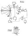
- Figure 1 there is shown a spherical piezoelectric ceramic cup 1, preferably mounted oscillating about an axis tangent to the cup at the top S thereof.
- the angular amplitude of oscillation will, for example, be between 30 and 60 °.
- the limits of the plane sector thus scanned by the axis SF of the cup are shown in dashed lines and in dashed lines the beam focused at F, emitted by the cup in its middle position.
- the oscillating movement of the cup is, in a manner known per se, obtained by means of an electric motor 2 controlled by a scanning generator 3 by means of an amplifier 4.
- An angular position sensor 5, of known type in itself, provides an electrical signal of variable amplitude as a linear function of the angle ⁇ made by the axis SF with its median reference position.
- such a sensor may comprise a permanent magnet secured to the motor shaft and cooperating with a magnetic field sensor.
- the signal indicative of ⁇ is applied to two operational amplifiers 6 and 7 which, moreover, receive two reference signals indicative of two particular values of ⁇ , namely ⁇ 1 and ⁇ 2. These reference signals are adjustable by means of potentiometers, 60 and 70 respectively.
- the output of modulator 9 is connected to the control input of a transmitter 10 via an OR gate 11, which moreover receives synchronization signals supplied by a clock 12.
- the transmitter 10 attacks the cup 1.
- This has for example a diameter of 70 mm and is composed, in a manner known per se, of a plurality of piezoelectric elements isolated from each other and juxtaposed to form a mosaic.
- the transmitter 10 can in reality comprise several emission devices each exciting a group of elements of the cup. This technique being known, will consider it, for the sake of clarity, that the transmitter 10 generates only one signal comprising, as will be explained below, both trains of power waves for treatment and ultrasound pulses.
- the carrier frequency will advantageously be the same, for example 5 MHz.
- the cup serves both as a transducer for transmitting power waves and ultrasound pulses, and for echo reception transducer formed by the reflection of ultrasound pulses on the target.
- the echoes received are transmitted to an ultrasound device 13, of a type known per se, via an amplifier 14.
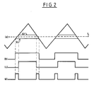
- Figure 2 shows in (a) the sawtooth signal generated by the sweep generator 3.
- this signal has a period of 1/5 sec., So that the oscillation frequency of the cup is 5 Hz.
- the signal (d) at the output of gate 8 thus comprises a slot at logic level 1 when ⁇ 1 ⁇ ⁇ ⁇ ⁇ 2, that is to say twice per period.
- the gate 11 transmits to the transmitter 10 the pulses of the clock 12, which for example have a high frequency of 5 MHz (therefore a duration of 0.2 ⁇ s) and a frequency 10 KHz recurrence. These values are suitable for the formation of a good quality ultrasound image with a scanning frequency of 5 Hz.
- the duration of the ultrasound emission it can be envisaged to make the transmitter 10 work at reduced power, for example, by reducing its supply voltage.
- each slot (d) which will be, for example, of the order of 20 ms, the transmitter 10 generates processing waves at the high frequency of 5 MHz.
- ⁇ 1 and ⁇ 2 are adjusted so that the target is located in the firing angle.
- FIG. 3 shows that the oscillating cup 1 and the motor 2 which drives it in oscillation are immersed in a coupling liquid contained in a housing 15, the front face of which is provided with a deformable membrane 150 transparent to ultrasound.
- This membrane has a sufficient surface to transmit the ultrasound scanning cone and is brought into contact with the patient's skin.
- the duration of emission for each train can vary between a few tens and a few hundred ⁇ s.
- the peak emission power the greater the shorter the train, may reach several hundreds of KW, the high peak powers and the brief emissions having the advantage of avoiding thermal diffusion of energy. which would reduce the accuracy of the shots.
Landscapes
- Engineering & Computer Science (AREA)
- Physics & Mathematics (AREA)
- Remote Sensing (AREA)
- Radar, Positioning & Navigation (AREA)
- Acoustics & Sound (AREA)
- Health & Medical Sciences (AREA)
- Life Sciences & Earth Sciences (AREA)
- General Physics & Mathematics (AREA)
- Public Health (AREA)
- Veterinary Medicine (AREA)
- Animal Behavior & Ethology (AREA)
- Radiology & Medical Imaging (AREA)
- Nuclear Medicine, Radiotherapy & Molecular Imaging (AREA)
- Biomedical Technology (AREA)
- Computer Networks & Wireless Communication (AREA)
- General Health & Medical Sciences (AREA)
- Multimedia (AREA)
- Surgical Instruments (AREA)
- Thermotherapy And Cooling Therapy Devices (AREA)
- Investigating Or Analyzing Materials By The Use Of Ultrasonic Waves (AREA)
- Transducers For Ultrasonic Waves (AREA)
- Ultra Sonic Daignosis Equipment (AREA)
- Laser Surgery Devices (AREA)
Claims (5)
- Ultraschall-Verarbeitungsvorrichtung mit einem Leistungswandler in Form einer autofokussierenden Schale (1), der einem Leistungsanregungsgenerator (10) und einer Echographievorrichtung (13) zugeordnet ist, die den Wandler als Echoempfänger verwendet, gekennzeichnet durch Mittel (2), um diesen Wandler währen der Betriebsdauer mit einer Geschwindigkeit und einer Amplitude, die für ein echographisches Abtasten eines gegebenen Schußraums in Echtzeit geeignet sind, periodisch um eine gegebene Stellung schwingen zu lassen, und durch Mittel (5 bis 12), um die Stellung des Wandlers zu erfassen und diesen Wandler mit Verarbeitungswellen zu Zeitpunkten anzuregen, in denen der Wandler in einer begrenzten vorbestimmten Zone seines Oszillationsbereichs schwingt, und ihn mit echographischen Wellen während des Intervalle zwischen diesen Zeitpunkten anzuregen.
- Vorrichtung nach Anspruch 1, dadurch gekennzeichnet, daß die Abtastung ein sektorielles Überstreichen vom Typ B ist und daß die Zeitpunkte dem Durchgang des Strahls durch einen begrenzten vorbestimmten Winkelsektor entsprechen.
- Vorrichtung nach Anspruch 2, dadurch gekennzeichnet, daß der begrenzte Sektor definiert wird durch einen Winkelstellungsgeber (5), während die Sendezeitpunkte der Verarbeitungswelle ausgehend von Angaben des Gebers durch logische Mittel (6 bis 11) definiert werden, die Rechtecksignale zur Leistungsaussendung erzeugen.
- Vorrichtung nach Anspruch 3, dadurch gekennzeichnet, daß die Echographieaussendung und die Leistungsaussendung den gleichen Anregungsgenerator (10) verwenden, die bei derselben Frequenz arbeiten.
- Vorrichtung nach Anspruch 1, gekennzeichnet durch eine lineare Schwenkbewegung des Wandlers.
Priority Applications (1)
| Application Number | Priority Date | Filing Date | Title |
|---|---|---|---|
| AT89402829T ATE90470T1 (de) | 1988-10-27 | 1989-10-13 | Ultraschallbehandlungsgeraet, gebrauchmachend von einer fokalisierenden und oszillierenden piezoelektrischen keramikvorrichtung. |
Applications Claiming Priority (2)
| Application Number | Priority Date | Filing Date | Title |
|---|---|---|---|
| FR8814015 | 1988-10-27 | ||
| FR8814015A FR2638532B1 (fr) | 1988-10-27 | 1988-10-27 | Dispositif de traitement par ultrasons utilisant une ceramique piezoelectrique focalisante et oscillante |
Publications (2)
| Publication Number | Publication Date |
|---|---|
| EP0370841A1 EP0370841A1 (de) | 1990-05-30 |
| EP0370841B1 true EP0370841B1 (de) | 1993-06-09 |
Family
ID=9371309
Family Applications (1)
| Application Number | Title | Priority Date | Filing Date |
|---|---|---|---|
| EP89402829A Expired - Lifetime EP0370841B1 (de) | 1988-10-27 | 1989-10-13 | Ultraschallbehandlungsgerät, gebrauchmachend von einer fokalisierenden und oszillierenden piezoelektrischen Keramikvorrichtung |
Country Status (10)
| Country | Link |
|---|---|
| EP (1) | EP0370841B1 (de) |
| JP (1) | JPH0779824B2 (de) |
| AT (1) | ATE90470T1 (de) |
| CA (1) | CA2001669C (de) |
| DD (1) | DD286433A5 (de) |
| DE (1) | DE68907024T2 (de) |
| ES (1) | ES2045507T3 (de) |
| FR (1) | FR2638532B1 (de) |
| MA (1) | MA21658A1 (de) |
| RU (1) | RU1829928C (de) |
Families Citing this family (7)
| Publication number | Priority date | Publication date | Assignee | Title |
|---|---|---|---|---|
| FR2664819B1 (fr) * | 1990-07-23 | 1994-04-29 | Edap Int | Appareil d'hyperthermie ultrasonore extracorporelle ultrarapide. |
| FR2685872A1 (fr) * | 1992-01-07 | 1993-07-09 | Edap Int | Appareil d'hyperthermie ultrasonore extracorporelle a tres grande puissance et son procede de fonctionnement. |
| DE4302538C1 (de) * | 1993-01-29 | 1994-04-07 | Siemens Ag | Therapiegerät zur Ortung und Behandlung einer im Körper eines Lebewesens befindlichen Zone mit akustischen Wellen |
| US6334846B1 (en) | 1995-03-31 | 2002-01-01 | Kabushiki Kaisha Toshiba | Ultrasound therapeutic apparatus |
| US5984881A (en) * | 1995-03-31 | 1999-11-16 | Kabushiki Kaisha Toshiba | Ultrasound therapeutic apparatus using a therapeutic ultrasonic wave source and an ultrasonic probe |
| CN100462116C (zh) * | 2004-07-29 | 2009-02-18 | 上海交通大学 | 功率超声换能器激励电路 |
| BRPI0822956A2 (pt) | 2008-07-24 | 2018-06-05 | Airbus Operations Ltd | dispositivo de inspeção ultrassônica para artefatos moldados |
Family Cites Families (4)
| Publication number | Priority date | Publication date | Assignee | Title |
|---|---|---|---|---|
| US4620546A (en) * | 1984-06-30 | 1986-11-04 | Kabushiki Kaisha Toshiba | Ultrasound hyperthermia apparatus |
| JPS61209643A (ja) * | 1985-03-15 | 1986-09-17 | 株式会社東芝 | 超音波診断治療装置 |
| US4773426A (en) * | 1985-06-03 | 1988-09-27 | Picker International, Inc. | Ultrasonic mechanical sector scanning transducer probe assembly |
| DE3736733A1 (de) * | 1986-10-29 | 1988-05-11 | Olympus Optical Co | Ultraschall-therapievorrichtung |
-
1988
- 1988-10-27 FR FR8814015A patent/FR2638532B1/fr not_active Expired - Lifetime
-
1989
- 1989-10-13 ES ES89402829T patent/ES2045507T3/es not_active Expired - Lifetime
- 1989-10-13 EP EP89402829A patent/EP0370841B1/de not_active Expired - Lifetime
- 1989-10-13 DE DE8989402829T patent/DE68907024T2/de not_active Expired - Fee Related
- 1989-10-13 AT AT89402829T patent/ATE90470T1/de not_active IP Right Cessation
- 1989-10-20 MA MA21910A patent/MA21658A1/fr unknown
- 1989-10-26 RU SU894742287A patent/RU1829928C/ru active
- 1989-10-26 DD DD89333933A patent/DD286433A5/de not_active IP Right Cessation
- 1989-10-27 JP JP1281562A patent/JPH0779824B2/ja not_active Expired - Lifetime
- 1989-10-27 CA CA002001669A patent/CA2001669C/fr not_active Expired - Fee Related
Also Published As
| Publication number | Publication date |
|---|---|
| ES2045507T3 (es) | 1994-01-16 |
| EP0370841A1 (de) | 1990-05-30 |
| ATE90470T1 (de) | 1993-06-15 |
| JPH02177957A (ja) | 1990-07-11 |
| FR2638532B1 (fr) | 1991-07-26 |
| MA21658A1 (fr) | 1990-07-01 |
| JPH0779824B2 (ja) | 1995-08-30 |
| CA2001669C (fr) | 1994-05-10 |
| RU1829928C (ru) | 1993-07-23 |
| DE68907024D1 (de) | 1993-07-15 |
| DD286433A5 (de) | 1991-01-24 |
| CA2001669A1 (fr) | 1990-04-27 |
| DE68907024T2 (de) | 1993-09-16 |
| FR2638532A1 (fr) | 1990-05-04 |
Similar Documents
| Publication | Publication Date | Title |
|---|---|---|
| US5143074A (en) | Ultrasonic treatment device using a focussing and oscillating piezoelectric element | |
| EP0162735B1 (de) | Vorrichtung zum Untersuchen und Lokalisieren von Tumoren mit Ultraschall, versehen mit einer Vorrichtung zur lokalen hyperthermischen Behandlung | |
| EP0148653B1 (de) | Vorrichtung zur Zertrümmerung von Konkrementen mit Ultraschallstosswellen | |
| EP0238589B1 (de) | Ortungsverfahren und -vorrichtung die eine abschätzung des zertrümmerungsgrades der konkremente während einer lithotripsie ermöglichen | |
| US4084582A (en) | Ultrasonic imaging system | |
| FR2597326A1 (fr) | Procede pour identifier des lesions tissulaires eventuelles lors de l'application medicale d'un son de haute energie. | |
| US4207901A (en) | Ultrasound reflector | |
| US4333474A (en) | Ultrasonic imaging system | |
| US4248090A (en) | Apparatus for ultrasonically imaging a body | |
| US4246791A (en) | Ultrasonic imaging apparatus | |
| EP0670147B1 (de) | Verfahren und Therapiegerät zur Erzeugung von Ultraschall mit reduzierter Kavitationsbildung | |
| EP0029578A1 (de) | Apparat zur Bilderzeugung mittels Ultraschall | |
| JPH074373B2 (ja) | 超音波内視鏡装置 | |
| FR2584148A1 (fr) | Generateur d'impulsions elastiques de grande puissance focalisees dans un liquide et obtenues par percussion | |
| EP0370841B1 (de) | Ultraschallbehandlungsgerät, gebrauchmachend von einer fokalisierenden und oszillierenden piezoelektrischen Keramikvorrichtung | |
| EP0310470A1 (de) | Verfahren und Vorrichtung zum Lokalisieren und Zertrümmern einer anatomischen Anomalie durch elastische Wellen mit Zielnachführung und automatischer Wellenauslösung | |
| EP0468847B1 (de) | Schnelles, extrakorporales Ultraschallhyperthermiegerät | |
| US4313444A (en) | Method and apparatus for ultrasonic Doppler detection | |
| JPH0738857B2 (ja) | 結石破砕装置 | |
| WO2017029599A1 (en) | Ultrasonic scanner with a plurality of transducers and method of use thereof | |
| RU2167500C1 (ru) | Способ измерения параметров шумности плавсредства с помощью лазерного гидрофона | |
| EP0632920B1 (de) | Therapiegerät mit variabler fokussierung ohne sekundärfokussierung | |
| JPS5821577A (ja) | 超音波送受信装置 | |
| JP2519688B2 (ja) | 超音波結石破砕装置 | |
| EP0040566A1 (de) | Echographisches Gerät mit dynamischer Fokussierung und Sektorabtastung |
Legal Events
| Date | Code | Title | Description |
|---|---|---|---|
| PUAI | Public reference made under article 153(3) epc to a published international application that has entered the european phase |
Free format text: ORIGINAL CODE: 0009012 |
|
| 17P | Request for examination filed |
Effective date: 19891017 |
|
| AK | Designated contracting states |
Kind code of ref document: A1 Designated state(s): AT BE CH DE ES GB GR IT LI NL SE |
|
| 17Q | First examination report despatched |
Effective date: 19920316 |
|
| GRAA | (expected) grant |
Free format text: ORIGINAL CODE: 0009210 |
|
| AK | Designated contracting states |
Kind code of ref document: B1 Designated state(s): AT BE CH DE ES GB GR IT LI NL SE |
|
| REF | Corresponds to: |
Ref document number: 90470 Country of ref document: AT Date of ref document: 19930615 Kind code of ref document: T |
|
| ITF | It: translation for a ep patent filed | ||
| REF | Corresponds to: |
Ref document number: 68907024 Country of ref document: DE Date of ref document: 19930715 |
|
| GBT | Gb: translation of ep patent filed (gb section 77(6)(a)/1977) |
Effective date: 19930629 |
|
| REG | Reference to a national code |
Ref country code: GR Ref legal event code: FG4A Free format text: 3008565 |
|
| REG | Reference to a national code |
Ref country code: ES Ref legal event code: FG2A Ref document number: 2045507 Country of ref document: ES Kind code of ref document: T3 |
|
| PLBE | No opposition filed within time limit |
Free format text: ORIGINAL CODE: 0009261 |
|
| STAA | Information on the status of an ep patent application or granted ep patent |
Free format text: STATUS: NO OPPOSITION FILED WITHIN TIME LIMIT |
|
| 26N | No opposition filed | ||
| PGFP | Annual fee paid to national office [announced via postgrant information from national office to epo] |
Ref country code: AT Payment date: 19940811 Year of fee payment: 6 |
|
| PGFP | Annual fee paid to national office [announced via postgrant information from national office to epo] |
Ref country code: GR Payment date: 19940817 Year of fee payment: 6 |
|
| PGFP | Annual fee paid to national office [announced via postgrant information from national office to epo] |
Ref country code: SE Payment date: 19940818 Year of fee payment: 6 |
|
| PGFP | Annual fee paid to national office [announced via postgrant information from national office to epo] |
Ref country code: BE Payment date: 19940831 Year of fee payment: 6 |
|
| PGFP | Annual fee paid to national office [announced via postgrant information from national office to epo] |
Ref country code: ES Payment date: 19940922 Year of fee payment: 6 |
|
| PGFP | Annual fee paid to national office [announced via postgrant information from national office to epo] |
Ref country code: CH Payment date: 19940930 Year of fee payment: 6 |
|
| PGFP | Annual fee paid to national office [announced via postgrant information from national office to epo] |
Ref country code: GB Payment date: 19941007 Year of fee payment: 6 |
|
| PGFP | Annual fee paid to national office [announced via postgrant information from national office to epo] |
Ref country code: NL Payment date: 19941031 Year of fee payment: 6 |
|
| EAL | Se: european patent in force in sweden |
Ref document number: 89402829.9 |
|
| PG25 | Lapsed in a contracting state [announced via postgrant information from national office to epo] |
Ref country code: GB Effective date: 19951013 Ref country code: AT Effective date: 19951013 |
|
| PG25 | Lapsed in a contracting state [announced via postgrant information from national office to epo] |
Ref country code: SE Effective date: 19951014 Ref country code: ES Free format text: LAPSE BECAUSE OF THE APPLICANT RENOUNCES Effective date: 19951014 |
|
| PG25 | Lapsed in a contracting state [announced via postgrant information from national office to epo] |
Ref country code: LI Effective date: 19951031 Ref country code: CH Effective date: 19951031 Ref country code: BE Effective date: 19951031 |
|
| BERE | Be: lapsed |
Owner name: EDAP INTERNATIONAL Effective date: 19951031 |
|
| PG25 | Lapsed in a contracting state [announced via postgrant information from national office to epo] |
Ref country code: GR Free format text: THE PATENT HAS BEEN ANNULLED BY A DECISION OF A NATIONAL AUTHORITY Effective date: 19960430 |
|
| PG25 | Lapsed in a contracting state [announced via postgrant information from national office to epo] |
Ref country code: NL Effective date: 19960501 |
|
| GBPC | Gb: european patent ceased through non-payment of renewal fee |
Effective date: 19951013 |
|
| REG | Reference to a national code |
Ref country code: CH Ref legal event code: PL |
|
| REG | Reference to a national code |
Ref country code: GR Ref legal event code: MM2A Free format text: 3008565 |
|
| EUG | Se: european patent has lapsed |
Ref document number: 89402829.9 |
|
| NLV4 | Nl: lapsed or anulled due to non-payment of the annual fee |
Effective date: 19960501 |
|
| REG | Reference to a national code |
Ref country code: ES Ref legal event code: FD2A Effective date: 19991007 |
|
| PGFP | Annual fee paid to national office [announced via postgrant information from national office to epo] |
Ref country code: DE Payment date: 20030214 Year of fee payment: 14 |
|
| PG25 | Lapsed in a contracting state [announced via postgrant information from national office to epo] |
Ref country code: DE Free format text: LAPSE BECAUSE OF NON-PAYMENT OF DUE FEES Effective date: 20040501 |
|
| PG25 | Lapsed in a contracting state [announced via postgrant information from national office to epo] |
Ref country code: IT Free format text: LAPSE BECAUSE OF NON-PAYMENT OF DUE FEES;WARNING: LAPSES OF ITALIAN PATENTS WITH EFFECTIVE DATE BEFORE 2007 MAY HAVE OCCURRED AT ANY TIME BEFORE 2007. THE CORRECT EFFECTIVE DATE MAY BE DIFFERENT FROM THE ONE RECORDED. Effective date: 20051013 |