EP0370842A1 - Ansatz zum Abgeben eines Produktes, insbesondere eines Schaumproduktes - Google Patents
Ansatz zum Abgeben eines Produktes, insbesondere eines Schaumproduktes Download PDFInfo
- Publication number
- EP0370842A1 EP0370842A1 EP89402879A EP89402879A EP0370842A1 EP 0370842 A1 EP0370842 A1 EP 0370842A1 EP 89402879 A EP89402879 A EP 89402879A EP 89402879 A EP89402879 A EP 89402879A EP 0370842 A1 EP0370842 A1 EP 0370842A1
- Authority
- EP
- European Patent Office
- Prior art keywords
- bore
- emerging
- valve
- rest position
- dispensing
- Prior art date
- Legal status (The legal status is an assumption and is not a legal conclusion. Google has not performed a legal analysis and makes no representation as to the accuracy of the status listed.)
- Withdrawn
Links
Images
Classifications
-
- B—PERFORMING OPERATIONS; TRANSPORTING
- B65—CONVEYING; PACKING; STORING; HANDLING THIN OR FILAMENTARY MATERIAL
- B65D—CONTAINERS FOR STORAGE OR TRANSPORT OF ARTICLES OR MATERIALS, e.g. BAGS, BARRELS, BOTTLES, BOXES, CANS, CARTONS, CRATES, DRUMS, JARS, TANKS, HOPPERS, FORWARDING CONTAINERS; ACCESSORIES, CLOSURES, OR FITTINGS THEREFOR; PACKAGING ELEMENTS; PACKAGES
- B65D83/00—Containers or packages with special means for dispensing contents
- B65D83/14—Containers for dispensing liquid or semi-liquid contents by internal gaseous pressure, i.e. aerosol containers comprising propellant
- B65D83/16—Actuating means
- B65D83/20—Actuator caps
-
- B—PERFORMING OPERATIONS; TRANSPORTING
- B05—SPRAYING OR ATOMISING IN GENERAL; APPLYING FLUENT MATERIALS TO SURFACES, IN GENERAL
- B05B—SPRAYING APPARATUS; ATOMISING APPARATUS; NOZZLES
- B05B11/00—Single-unit hand-held apparatus in which flow of contents is produced by the muscular force of the operator at the moment of use
- B05B11/01—Single-unit hand-held apparatus in which flow of contents is produced by the muscular force of the operator at the moment of use characterised by the means producing the flow
- B05B11/10—Pump arrangements for transferring the contents from the container to a pump chamber by a sucking effect and forcing the contents out through the dispensing nozzle
- B05B11/1097—Pump arrangements for transferring the contents from the container to a pump chamber by a sucking effect and forcing the contents out through the dispensing nozzle with means for sucking back the liquid or other fluent material in the nozzle after a dispensing stroke
Definitions
- the present invention relates to a nozzle for dispensing a product, in particular a foaming product, contained in a pressurized container equipped with an emerging stem valve mounted in a valve cup.
- a dispensing nozzle for a pressurized container has a fastening element on the container.
- This element can be, for example, a latching or fitting device on the retaining flange of the valve cup on the container.
- the nozzle also comprises, in a known manner, an ejection tube, this ejection tube possibly being in a plane perpendicular to the axis of the emerging stem of the valve or making a slight angle relative to such a plane; this ejection tube communicates with the emerging stem of the valve by a bore of the same axis as said emerging stem.
- the emerging rod When the user presses on the dispensing nozzle, to actuate the valve, the emerging rod is introduced into the bore up to a range, where the junction between the valve and the bore is tight, then the bore transmits the push of the user to the emerging rod so as to push the latter and open the valve.
- the emerging rod moves in a bore having a shape such that in the operating position, the junction between the rod and the bore is sealed and that in the rest position, it is not not.
- the product which remains in the ejection tube and the bore, has the possibility of flowing in the space between the valve cup and the dispensing nozzle.
- Non-sealing can be obtained using grooves hollowed out in the bore, as described in French patent application No. 06 06273, or by arranging so that in the rest position, the rod emerging from the valve is completely out of the bore.
- the present application relates to a dispensing nozzle, in which a vacuum is created in a chamber between the ejection tube and the valve cup, when the dispensing is stopped, and in which the vacuum caused is precisely controlled. .
- the present invention relates to a nozzle for dispensing a product, in particular a foaming product, contained in a pressurized container equipped with a valve with an emerging stem mounted in a valve cup, said nozzle comprising: - first, a fastening element on the container.
- a distribution element comprising, on the one hand, a bore, one bearing of which is intended to receive the free end of the emerging valve stem in the operating position, when the user presses on the element distribution, said bore having the same axis as the emerging rod with which it cooperates, on the other hand, an ejection tube perpendicular to the axis of said bore or slightly inclined relative to a perpendicular to said axis, this tube ejection being in communication with said bore, and finally, a bearing surface allowing the action of the user on the tip, - and thirdly, a lateral junction element between the fixing element and the distribution element, characterized by the fact that the dispensing element is entirely rigid and that the junction element is organized symmetrically with respect to the axis of the emerging rod and has an elasticity such that its height h can vary, between the operating position and the rest position, with a value ⁇ h equal to the sum of the distance ⁇ h1 between the upper edge of the emerging rod in the rest position and the range of the bore
- the joining element consists of a bellows, the very shape of which provides the necessary elasticity even if the material used has a relative rigidity.
- the junction element has the shape of a dome and, in this case, it is made of an elastic plastic material such as polyethylene, polyvinyl chloride or the like.
- the distance ⁇ h is preferably between 2 mm and 15 mm for tips having a diameter of 15mm to 35 mm.
- the dispensing element may constitute a part assembled on the junction element or to be molded in one piece with said junction element.
- the fixing element and the joining element form a single piece.
- the tip according to the present invention works as follows.
- the user presses on the rigid dispensing element it causes the progressive reduction in the height of the junction element and, consequently, the reduction in the volume of the chamber included inside the end piece. above the valve cup.
- the bore is moved towards, then pressed on the valve stem until it comes into abutment on the bearing surface; then the bore causes the emergence of the emerging valve stem: the distribution of the product begins.
- the emerging stem of the valve rises, the bore disengages from the emerging stem of the valve and, thanks to its elasticity, the lateral junction element regularly resumes its initial height.
- This depression is well controlled because the user presses on a rigid surface and the reduction in the volume of the chamber is silenced regularly over the entire cross section thereof; this eliminates irregularities due to the way in which the user presses on the dispensing element, irregularities which exist in the case where the dispensing element is not entirely rigid.
- the symmetry of the junction element with respect to the axis of the valve results in a substantially axial deformation so that the bore of the dispensing element is correctly adjusted on the emerging rod at the end of the deformation.
- the depression causes the suction of the product contained in the ejection channel, that is to say in the ejection tube and in the bore; said product flows inside the chamber.
- the aspirated product gradually dries; if a new use is made later, said product is dried but the dry extract remains in the chamber and does not interfere with the further distribution.
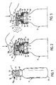
- the dispensing nozzle 1 is fixed to a pressurized container 2 of generally cylindrical shape.
- the container 2 has a bottom 21 and it is closed, at the end opposite the bottom 21, by a valve cup 3, which is fixed to the container 2 by a bead 31.
- the dispensing valve 4 is placed in the center of the valve cup and it has an emerging rod 41 axially.
- the end piece 1 consists of three elements: a distribution element 5, a fixing element 6 and a lateral junction element 7, which connects the distribution element and the 'element of fixation.
- the dispensing element 5 is molded from a rigid plastic material; it comprises an axial bore 51 which comprises, moving axially from the inside towards the outside of the end piece, a frustoconical part 51 a , followed by a cylindrical part 51 b having an inside diameter slightly greater than the outside diameter of the valve stem 41 and of a part 51 c of smaller diameter than the part 51 b so as to form an annular seat 51 d which serves as a sealed stop for the emerging rod 41.
- the dispensing element 5 also includes a ejection tube 52 whose inner channel 52 a communicates with the bore 51. Above the dispensing element 5 is a bearing surface 53, on which the user can press to actuate the end piece distribution.
- the fastening element 6 is snapped onto the retaining flange 31 of the valve cup on the container 2. It consists of a cylindrical skirt 61 comprising, on the side of the container 2, a snap flange 62 disposed under the bead 31 and, on the side of the dispensing element 5, of an annular planar portion 63, which rests on the edge of the valve cup 3.
- the lateral junction element 7 is constituted by a bellows constructed, for example, from flexible, elastically deformable plastic. According to the embodiment described, the fixing element 6 and the lateral joining element 7 are molded in one piece.
- the joining element 7 comprises, at its upper part, a cylindrical part 71, in which the distribution element 5 is fitted, which has been molded separately from a rigid plastic material.
- the lateral junction element 7 internally delimits a chamber 72.
- the device works as follows: when the user wishes to actuate the dispensing endpiece, he presses with a finger on the bearing surface 53 of the dispensing element. It thus pushes in the distribution element 5, which has the consequence of causing the reduction in the height of the junction element 7, the accordion parts being folded over one another. At the same time, the upper edge of the emerging rod 41 enters part 51 a of the bore and then part 51 b . When it reaches the bottom of the part 51 b , the emerging rod is in abutment against the annular bearing surface 51 d which exists because the part 51 c has a smaller diameter than the part 51 b : the upper edge 41 a of the emerging rod therefore abuts against the bearing 51 d .
- the thrust of the user therefore causes the valve rod 41 to sink, which causes the valve 4 to open.
- the height of the chamber 72 decreases, air is expelled by the bore 51 and the ejectlon tube 52.
- the height of the lateral chamber has decreased by a value ⁇ h (see FIG. 4), which is the sum of the distance ⁇ h1 measured, in the rest position, between the upper rim 41 a of the emerging rod and the bearing surface 51 d of the bore, and of the distance ⁇ h2 corresponding to the driving stroke of the emerging rod.
- the variation in volume of the chamber 72 does not depend on how the user presses on the dispensing element but only on the final position of the dispensing element which is always the same. Depression is therefore reproducible reliably; it causes the aspiration of products, which would have remained in the channel 52 a of the ejection tube and in the bore 51; the liquid falls into the chamber 72.
- the variation in pressure being reliable and reproducible, this suction is therefore always possible insofar as the variation in volume of the chamber, that is to say the variation in height ⁇ h has been determined properly.
- the variation ⁇ h in height is, for example, 10 mm for an internal chamber diameter of 25 mm.
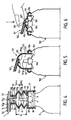
- Figures 5 and 6 show a second embodiment of a dispensing nozzle according to the present invention.
- the constituent elements which are analogous or have a function similar to those described in connection with FIGS. 1 to 4, will be designated by references equal to the sum of the number 100 and the reference used for the corresponding element in FIGS. 1 to 4. The description will therefore only be made succinctly.
- the dispensing nozzle 101 comprises a dispensing element 105, a fixing element 106 clipped onto the container 102 and a lateral joining element 107 connecting the fixing element 106 to the distributing element 105
- the distribution element 105 has a bore 151 and a distribution tube 152 which is slightly inclined relative to a plane perpendicular to the axis of the emerging rod 141 of the valve. 104.
- the fixing element 106 is obtained by molding in one piece with the lateral joining element 107 the distribution element 105.
- Said fixing element 106 comprises two circular skirts of the same axis as the emerging rod 141, which allow it to snap onto the fixing bead 131 of the valve cup 103 on the container 102.
- the lateral junction element 107 has the shape of a thin dome capable of elastic deformation.
- This nozzle is made of elastic material, for example polyethylene, and the rigidity of the dispensing element 105 is obtained by a sufficient excess thickness of material in the support area of the user.
- FIG. 5 represents the nozzle in the rest position and FIG. 6 represents the nozzle in the operating position when the user has pressed on the dispensing element 105 until the valve 104 opens.
- the variation in volume of the chamber 172 does not depend on the way in which the user presses on the dispensing device 105, this variation in volume is controllable and reproducible in a reliable manner due to the symmetry of the deformable part of the tip and the rigidity of the dispensing tip on which the user presses. Aspiration of the remaining liquid, contained in the ejection tube 152 and in the bore 151, is therefore always possible, even with thick liquids.
Landscapes
- Chemical & Material Sciences (AREA)
- Dispersion Chemistry (AREA)
- Engineering & Computer Science (AREA)
- Mechanical Engineering (AREA)
- Containers And Packaging Bodies Having A Special Means To Remove Contents (AREA)
- Closures For Containers (AREA)
Applications Claiming Priority (2)
| Application Number | Priority Date | Filing Date | Title |
|---|---|---|---|
| FR8815100 | 1988-11-21 | ||
| FR8815100A FR2639259B1 (fr) | 1988-11-21 | 1988-11-21 | Embout pour distribuer un produit, en particulier un produit moussant |
Publications (1)
| Publication Number | Publication Date |
|---|---|
| EP0370842A1 true EP0370842A1 (de) | 1990-05-30 |
Family
ID=9372030
Family Applications (1)
| Application Number | Title | Priority Date | Filing Date |
|---|---|---|---|
| EP89402879A Withdrawn EP0370842A1 (de) | 1988-11-21 | 1989-10-18 | Ansatz zum Abgeben eines Produktes, insbesondere eines Schaumproduktes |
Country Status (5)
| Country | Link |
|---|---|
| US (1) | US4978035A (de) |
| EP (1) | EP0370842A1 (de) |
| JP (1) | JPH02203951A (de) |
| CA (1) | CA2003369A1 (de) |
| FR (1) | FR2639259B1 (de) |
Cited By (5)
| Publication number | Priority date | Publication date | Assignee | Title |
|---|---|---|---|---|
| TR26659A (tr) * | 1991-10-30 | 1995-03-15 | Gillette Co | Dagitma aleti icin isletme ve baslik kismi |
| US5732855A (en) * | 1995-03-06 | 1998-03-31 | Park Towers International B.V. | Spray head intended for a spray can, and spray can provided with such a spray head |
| US6405898B1 (en) | 2000-11-16 | 2002-06-18 | The Gillette Company | Dispenser for a foaming product |
| WO2016008930A1 (en) * | 2014-07-15 | 2016-01-21 | L'oreal | Actuating and product dispensing head, related device and method |
| FR3065653A1 (fr) * | 2017-04-27 | 2018-11-02 | Aptar France Sas | Tete de distribution de produit fluide. |
Families Citing this family (49)
| Publication number | Priority date | Publication date | Assignee | Title |
|---|---|---|---|---|
| US5137180A (en) * | 1990-09-06 | 1992-08-11 | Pittway Corporation | Vented aerosol device |
| USD343789S (en) | 1991-10-30 | 1994-02-01 | The Gillette Company | Combination actuator and hood for dispensing foam material |
| USD339739S (en) | 1991-10-30 | 1993-09-28 | The Gillette Company | Combination actuator and hood for dispensing gel material |
| USD349854S (en) | 1991-11-04 | 1994-08-23 | The Gillette Company | Actuator turret for gel dispenser |
| USD349853S (en) | 1991-11-04 | 1994-08-23 | The Gillette Company | Actuator turret for foam dispenser |
| USD349846S (en) | 1992-03-17 | 1994-08-23 | The Gillette Company | Combination actuator and hood for dispensing foam material |
| USD349845S (en) | 1992-03-17 | 1994-08-23 | The Gillette Company | Combination actuator and hood for dispensing gel material |
| DE9390268U1 (de) * | 1993-05-24 | 1995-02-23 | Deutsche Präzisions-Ventil GmbH, 65795 Hattersheim | Betätigungsteil für einen Aerosol-Behälter |
| US5370284A (en) * | 1994-03-15 | 1994-12-06 | The Procter & Gamble Company | Toggle closure for a resiliently deformable container |
| US5918777A (en) * | 1996-02-21 | 1999-07-06 | Owens-Brockway Plastic Products Inc. | Dispensing package for viscous liquid product |
| FR2768409B1 (fr) * | 1997-09-17 | 1999-10-15 | Oreal | Ensemble de conditionnement et de distribution d'un produit liquide ou semi liquide |
| USD413794S (en) * | 1998-03-16 | 1999-09-14 | W. Braum Company | Container with integral bellows pump |
| US6241128B1 (en) | 1998-12-22 | 2001-06-05 | Owens-Brockway Plastic Products Inc. | Dispenser package for fluent products and method of manufacture |
| USD424441S (en) * | 1999-02-12 | 2000-05-09 | Taplast Spa | Dosing cap |
| FR2792913B1 (fr) | 1999-04-29 | 2001-06-01 | Oreal | Dispositif pour l'actionnement d'un organe de distribution notamment une valve, et ensemble equipe du dispositif d'actionnement selon l'invention |
| US6394323B2 (en) | 1999-08-24 | 2002-05-28 | Owens-Brockway Plastic Products Inc. | Dispenser package for fluent products and method of manufacture |
| US6311878B1 (en) | 2000-01-07 | 2001-11-06 | Owens-Brockway Plastics Products Inc. | Dispensing package for fluent products |
| USD452822S1 (en) | 2000-03-22 | 2002-01-08 | Airspray International B.V. | Foam dispenser |
| FR2806933B1 (fr) * | 2000-03-31 | 2003-04-11 | Oreal | Bouton-poussoir a effet ressort |
| USD438468S1 (en) | 2000-06-09 | 2001-03-06 | Calmar Inc. | Dispenser head |
| USD438798S1 (en) | 2000-06-09 | 2001-03-13 | Calmar Inc. | Dispenser head |
| USD438113S1 (en) | 2000-06-09 | 2001-02-27 | Calmar Inc. | Dispenser head |
| US6971557B2 (en) * | 2003-06-19 | 2005-12-06 | S. C. Johnson & Son, Inc. | Actuator for a pressurized material dispenser |
| USD537720S1 (en) * | 2004-01-16 | 2007-03-06 | James Watson | Bottle |
| DE102004003264A1 (de) * | 2004-01-21 | 2005-08-18 | Fazekas, Gàbor | Adapter für Aerosoldosen |
| US7044338B2 (en) * | 2004-02-10 | 2006-05-16 | Roden William C | Aerosol product dispenser system |
| EP1786701A1 (de) * | 2004-08-03 | 2007-05-23 | Incro Limited | Spender für aerosolschäume und ähnliches mit einer nach-expansionskammer |
| USD529384S1 (en) * | 2005-07-05 | 2006-10-03 | Airspray International B.V. | Dispenser for liquid soap |
| US9649513B2 (en) * | 2006-03-24 | 2017-05-16 | Colgate—Palmolive Company | Aerosol dispenser |
| US7780039B2 (en) * | 2006-04-28 | 2010-08-24 | Buckeye International, Inc. | Soap dispensing pump head with vacuum applying drip guard member |
| CA2666408C (en) * | 2006-10-20 | 2015-07-07 | Glaxosmithkline Consumer Healthcare Gmbh & Co. Kg | Dispenser cap for pressurized fluids |
| CA2585397A1 (en) * | 2007-04-19 | 2008-10-19 | Felix Caron | Dispenser |
| US7726517B2 (en) * | 2007-06-27 | 2010-06-01 | The Clorox Company | Liquid draw-back system for a dispensing package |
| GB2463716A (en) * | 2008-09-24 | 2010-03-31 | Robinson Plc | A dispensing cap having an expansion chamber to contain residual product |
| JP5566724B2 (ja) * | 2010-03-02 | 2014-08-06 | 東洋エアゾール工業株式会社 | エアゾール内容物噴射装置 |
| USD667730S1 (en) | 2010-11-05 | 2012-09-25 | Colgate-Palmolive Company | Container |
| USD667728S1 (en) | 2010-11-05 | 2012-09-25 | Colgate-Palmolive Company | Container |
| CA2802570C (en) * | 2012-01-19 | 2015-06-09 | Lloyd Hornland | Combined cap and actuator device for aerosol container |
| NL2011199C2 (en) * | 2013-07-19 | 2015-01-21 | Jan Kelders Beheer B V | Dispenser and method for dispensing fluids from a liquid holder. |
| USD717666S1 (en) | 2014-03-14 | 2014-11-18 | The Clorox Company | Fluid dispenser |
| USD784726S1 (en) | 2014-12-23 | 2017-04-25 | Buckeye International, Inc. | Dispenser for dispensing cleaning solutions |
| US10647501B2 (en) | 2015-04-06 | 2020-05-12 | S. C. Johnson & Son, Inc. | Dispensing systems |
| USD795608S1 (en) | 2015-10-12 | 2017-08-29 | Buckeye International, Inc. | Dispenser for dispensing cleaning solutions, a cover piece for a dispenser for dispensing cleaning solutions, and a portion of a dispenser for dispensing cleaning solutions |
| US9919327B2 (en) * | 2016-06-21 | 2018-03-20 | Avon Products, Inc. | Living hinge actuator |
| DE102017118704A1 (de) * | 2017-08-16 | 2019-02-21 | Gábor Fazekas | Feststoffventile für Druckdosen |
| USD913804S1 (en) * | 2019-05-06 | 2021-03-23 | Natura Cosméticos S.A. | Flask |
| EP4017812B1 (de) * | 2019-10-31 | 2025-04-02 | Colgate-Palmolive Company | Behälter |
| JP7193693B2 (ja) | 2020-09-11 | 2022-12-21 | 東洋製罐株式会社 | 吐出装置および無人航空機 |
| DE102024107206A1 (de) | 2024-03-13 | 2025-09-18 | Gábor Fazekas | Adapter |
Citations (3)
| Publication number | Priority date | Publication date | Assignee | Title |
|---|---|---|---|---|
| US2772819A (en) * | 1955-04-27 | 1956-12-04 | Avoset Company | Lever type dispenser system for pressurized containers |
| US2894660A (en) * | 1958-05-13 | 1959-07-14 | Edward L Gordon | Dispenser cap |
| US3785528A (en) * | 1972-08-21 | 1974-01-15 | Vca Corp | Aerosol dispensing device |
Family Cites Families (6)
| Publication number | Priority date | Publication date | Assignee | Title |
|---|---|---|---|---|
| US2681752A (en) * | 1950-10-09 | 1954-06-22 | Nat Dispenser Corp | Dispenser valve for containers for viscous fluids under pressure |
| US2908479A (en) * | 1957-11-04 | 1959-10-13 | Cornell Valve Corp | Aerosol valve |
| US3377005A (en) * | 1967-02-03 | 1968-04-09 | American Home Prod | Aerosol container overcap with oozeproof valve-actuating means |
| US3578220A (en) * | 1969-03-17 | 1971-05-11 | Scovill Manufacturing Co | Aerosol valve actuator and cap combination |
| US4034427A (en) * | 1976-01-26 | 1977-07-12 | The Clorox Company | Aerosol drain opener device |
| FR2598101B1 (fr) * | 1986-04-30 | 1988-08-05 | Oreal | Embout pour distribuer un produit moussant |
-
1988
- 1988-11-21 FR FR8815100A patent/FR2639259B1/fr not_active Expired - Lifetime
-
1989
- 1989-10-18 EP EP89402879A patent/EP0370842A1/de not_active Withdrawn
- 1989-11-20 CA CA002003369A patent/CA2003369A1/fr not_active Abandoned
- 1989-11-21 JP JP1300953A patent/JPH02203951A/ja active Pending
- 1989-11-21 US US07/439,975 patent/US4978035A/en not_active Expired - Fee Related
Patent Citations (3)
| Publication number | Priority date | Publication date | Assignee | Title |
|---|---|---|---|---|
| US2772819A (en) * | 1955-04-27 | 1956-12-04 | Avoset Company | Lever type dispenser system for pressurized containers |
| US2894660A (en) * | 1958-05-13 | 1959-07-14 | Edward L Gordon | Dispenser cap |
| US3785528A (en) * | 1972-08-21 | 1974-01-15 | Vca Corp | Aerosol dispensing device |
Cited By (7)
| Publication number | Priority date | Publication date | Assignee | Title |
|---|---|---|---|---|
| TR26659A (tr) * | 1991-10-30 | 1995-03-15 | Gillette Co | Dagitma aleti icin isletme ve baslik kismi |
| EP0609262A4 (en) * | 1991-10-30 | 1996-04-10 | Gillette Co | Actuator and hood for dispensing device. |
| US5732855A (en) * | 1995-03-06 | 1998-03-31 | Park Towers International B.V. | Spray head intended for a spray can, and spray can provided with such a spray head |
| US6405898B1 (en) | 2000-11-16 | 2002-06-18 | The Gillette Company | Dispenser for a foaming product |
| WO2016008930A1 (en) * | 2014-07-15 | 2016-01-21 | L'oreal | Actuating and product dispensing head, related device and method |
| FR3023733A1 (fr) * | 2014-07-15 | 2016-01-22 | Oreal | Tete d'actionnement et de distribution d'un produit, dispositif et procede associes |
| FR3065653A1 (fr) * | 2017-04-27 | 2018-11-02 | Aptar France Sas | Tete de distribution de produit fluide. |
Also Published As
| Publication number | Publication date |
|---|---|
| FR2639259A1 (fr) | 1990-05-25 |
| US4978035A (en) | 1990-12-18 |
| FR2639259B1 (fr) | 1991-03-29 |
| CA2003369A1 (fr) | 1990-05-21 |
| JPH02203951A (ja) | 1990-08-13 |
Similar Documents
| Publication | Publication Date | Title |
|---|---|---|
| FR2639259A1 (fr) | Embout pour distribuer un produit, en particulier un produit moussant | |
| EP0410857B1 (de) | Abgabevorrichtung für wenigstens ein Produkt, insbesondere kosmetischer Art, wie Creme, Fluid oder Puder | |
| EP0524854B1 (de) | Verstellbares Ventil und Spender mit einem solchen Ventil | |
| EP0549050B1 (de) | Abgabevorrichtung für wenigstens ein flüssiges Produkt, insbesondere kosmetischer oder pharmazeutischer Art | |
| EP2136931B1 (de) | Vorrichtung zur ausgabe eines flüssigen bis pastösen produkts mittels dosierpumpe | |
| EP0453357B1 (de) | Sprüh- und Dosiervorrichtung | |
| EP0416971B1 (de) | Verstellbare Handpumpe auf dem Hals eines Gefässes | |
| EP0278828B1 (de) | Behälter zum Handhaben und zur kontrollierten Ausgabe eines Produktes, mit einer Bürste als Aufträger | |
| FR2654078A1 (fr) | Obturateur du canal de sortie d'une tete de distribution pour produits pateux et tete de distribution avantageusement associee. | |
| WO1997015509A2 (fr) | Distributeur de produits liquides ou pateux | |
| FR2549015A1 (fr) | Ensemble compte-gouttes | |
| EP3417948B1 (de) | Gegossene pumpe für die verteilung eines fluidprodukts | |
| EP0960829B1 (de) | Ventil sowie Aufbewahrungs- und Ausgabevorrichtung mit einem solchen Ventil | |
| WO2000020294A1 (fr) | Distributeur a mode de delivrance peripherique | |
| EP1127624B1 (de) | Pumpe mit einer als Feder wirkenden Membrane and Behälter mit einer solchen Pumpe | |
| EP2069076B1 (de) | Spendevorrichtung für ein flüssiges produkt | |
| FR2903092A1 (fr) | Distributeur de produit fluide | |
| EP0271526B1 (de) | Kopf für die abgabe von halbflüssigem, teigigem oder zähflüssigem medium | |
| EP0605275B1 (de) | Anordnung zur Zerstäubung einer Flüssigkeit mit einer Vordruckpumpe | |
| EP1633647B1 (de) | Fluidproduktspender | |
| FR2884157A1 (fr) | Tete de distribution | |
| FR2671330A1 (fr) | Distributeur manuel portatif a pompe pour creme et cosmetique. | |
| EP2069077A1 (de) | Spender für ein flüssigprodukt | |
| FR2678906A1 (fr) | Dispositif pour projeter une dose predeterminee d'un produit fluide, et son procede de remplissage. | |
| EP1857186B1 (de) | Spender für fliessfähige Produkte mit einer Druckkolbenpumpe und einer Membrane |
Legal Events
| Date | Code | Title | Description |
|---|---|---|---|
| PUAI | Public reference made under article 153(3) epc to a published international application that has entered the european phase |
Free format text: ORIGINAL CODE: 0009012 |
|
| 17P | Request for examination filed |
Effective date: 19891020 |
|
| AK | Designated contracting states |
Kind code of ref document: A1 Designated state(s): DE ES FR GB IT NL SE |
|
| 17Q | First examination report despatched |
Effective date: 19920407 |
|
| STAA | Information on the status of an ep patent application or granted ep patent |
Free format text: STATUS: THE APPLICATION IS DEEMED TO BE WITHDRAWN |
|
| 18D | Application deemed to be withdrawn |
Effective date: 19920909 |