EP0370846B1 - Elektroakustischer Wandler - Google Patents
Elektroakustischer Wandler Download PDFInfo
- Publication number
- EP0370846B1 EP0370846B1 EP89402966A EP89402966A EP0370846B1 EP 0370846 B1 EP0370846 B1 EP 0370846B1 EP 89402966 A EP89402966 A EP 89402966A EP 89402966 A EP89402966 A EP 89402966A EP 0370846 B1 EP0370846 B1 EP 0370846B1
- Authority
- EP
- European Patent Office
- Prior art keywords
- electrodes
- electroacoustic transducer
- transducer according
- ion
- electrode
- Prior art date
- Legal status (The legal status is an assumption and is not a legal conclusion. Google has not performed a legal analysis and makes no representation as to the accuracy of the status listed.)
- Expired - Lifetime
Links
Images
Classifications
-
- H—ELECTRICITY
- H04—ELECTRIC COMMUNICATION TECHNIQUE
- H04R—LOUDSPEAKERS, MICROPHONES, GRAMOPHONE PICK-UPS OR LIKE ACOUSTIC ELECTROMECHANICAL TRANSDUCERS; ELECTRIC HEARING AIDS; PUBLIC ADDRESS SYSTEMS
- H04R23/00—Transducers other than those covered by groups H04R9/00 - H04R21/00
- H04R23/004—Transducers other than those covered by groups H04R9/00 - H04R21/00 using ionised gas
Definitions
- the present invention relates to an electroacoustic transducer, as well as an acoustic enclosure comprising at least one such transducer.
- an electroacoustic transducer comprising a wire capable of emitting ions when it is brought to a sufficiently high potential, said wire being arranged between two electrodes, one parallel to the other, connected to a modulator, between which is likely to be created a modulated electric field acting on said ions. Said ions are then set in motion and transmit, by collisions, the energy thus acquired to the surrounding neutral molecules, producing a sound at the frequency of the modulated electric field.
- the emission of ions is very localized, in the immediate vicinity of the wire, so that the results obtained are hardly satisfactory in practice.
- an electroacoustic transducer of the type comprising at least one element capable of emitting ions when it is brought to a sufficiently high electrical potential, said element being arranged at neighborhood of two first electrodes, parallel to each other, connected to a modulator, between which a modulated electric field is likely to be created, and at least a second electrode having an electrical potential such as a flux of ions are created between said ion emitter and said second electrode, so that said modulated electric field acts on said ion flux.
- the present invention aims to improve the latter transducer, and relates to an electroacoustic transducer whose efficiency is greatly improved.
- the transducer of the type described in document US-A-3 022 385 is characterized in that said ion-emitting element is arranged between said two first electrodes, and in that said second electrode is arranged in the vicinity of said ion emitting element so that said ion flow forms a vibrating membrane between said ion emitting element and said second electrode.
- said ion flow plays the role of an immaterial vibrating membrane.
- the ionized fluid, created between the ion-emitting element and the second electrode is attracted by the first electrodes at the rate of the modulation, thereby generating acoustic pressures in the air.
- said ion emitting element is a wire
- two said second parallel electrodes are provided on either side of said wire respectively, said second electrodes being orthogonal to said first electrodes.
- said second electrodes are arranged at equal distances from said wire.
- the latter in particular in stainless steel or platinum, can have a diameter of between 20 and 50 micrometers.
- said ion emitting element is a point
- either a plurality of second point electrodes are arranged in a fan around said point, or said second electrode has approximately the shape of a horseshoe surrounding said point.
- said first electrodes are arranged at equal distances from said ion emitting element.
- said first electrodes are grids of rigid textile material covered with carbon.
- said ion-emitting element is brought to a negative potential of the order of at least -4.5 kV.
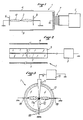
- Figures 1 and 2 illustrate a first embodiment of the electroacoustic transducer of the invention, in which the ion emitting element is a wire.
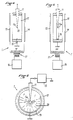
- Figures 3 and 4, and 5 and 6 illustrate, respectively, two variants of a second embodiment of the electroacoustic transducer of the invention, in which the ion emitting element is a tip.
- the electroacoustic transducer 1 comprises a wire 2, connected to a high voltage source 3, capable of emitting ions when it is brought to a sufficiently high electrical potential, for example a negative potential of the order of - 4.5 kV at least, negative potential giving no discharge noises.
- the wire 2 is arranged between two first electrodes 4,5, parallel to each other, connected to a modulator 6 via a transformer 7.
- a modulated electric field can thus be created between the two electrodes 4 , 5, to act on said ions.
- the electrodes 4,5 are advantageously produced in the form of grids of rigid textile material covered with carbon. As a result, the formation of arcs in the presence of strong modulations is extremely rare, and these are not maintained as they would be with metal grids.
- first 4.5 and second 8.9 electrodes are advantageously arranged at equal distances from the wire, respectively, so as to avoid creating an ionic wind during the application of the negative voltage. of polarization.
- the modulated electric field created between the first electrodes 4,5 thus acts on the ion flow 10, generated between the wire 2 and the second electrodes 8,9, playing the role of a non-material vibrating membrane.
- the ionized fluid created between the wire 2 and the ground electrodes 8, 9 is attracted by the grids 4.5 at the rate of the modulation, thereby producing acoustic pressures in the air.
- the ion-emitting wire is replaced by a tip.
- the tip 11 is arranged in a support ring 12, so that the tip 11a thereof is located in the center of said ring 12.
- the tip 11 connected to a high voltage source 13 is capable of emitting ions when it is brought to a sufficiently high electrical potential, for example a negative potential of the order of -4.5 kV.
- the tip 11, and in particular the tip 11a thereof is arranged between two first electrodes 14,15, parallel to each other, connected to a modulator 16 by means of a transformer 17.
- These electrodes 14,15 are advantageously of the same type as the electrodes 4,5 described above.
- a plurality of second point electrodes 18 (for example three electrodes 18), connected to ground, are arranged in a fan around the end 11a of the tip 11.
- a second single electrode 19 connected to ground, having approximately the shape of a horseshoe surrounds the tip 11a of the tip 11.
- the modulated electric field created between the first electrodes 14,15 and the tip 11 acts on the ion flow 20, generated between the tip 2 and the second electrode (s) 18,19, playing the role of immaterial vibrating membrane.
Landscapes
- Physics & Mathematics (AREA)
- Engineering & Computer Science (AREA)
- Acoustics & Sound (AREA)
- Signal Processing (AREA)
- Electrostatic, Electromagnetic, Magneto- Strictive, And Variable-Resistance Transducers (AREA)
- Audible-Bandwidth Dynamoelectric Transducers Other Than Pickups (AREA)
- Piezo-Electric Transducers For Audible Bands (AREA)
- Transducers For Ultrasonic Waves (AREA)
- Diaphragms For Electromechanical Transducers (AREA)
- Physical Or Chemical Processes And Apparatus (AREA)
Claims (10)
- Elektroakustischer Wandler, mit zumindest einem Element (2, 11), das geeignet ist, Ionen zu emittieren, wenn es auf ein ausreichend hohes elektrisches Potential gebracht wird, wobei das Element (2, 11) in der Nähe von zwei ersten Elektroden (4, 5; 14, 15) angeordnet ist, die parallel zueinander liegen, die mit einem Modulator verbunden sind und zwischen denen ein moduliertes elektrisches Feld erzeugbar ist, und mit zumindest einer zweiten Elektrode (8, 9; 18; 19) mit einem solchen elektrischen Potential, daß ein Ionenstrom (10, 20) zwischen dem Ionenemitter (2, 11) und der zweiten Elektrode (8, 9; 18; 19) erzeugt wird, so daß das modulierte elektrische Feld auf den Ionenstrom (10, 20) wirkt, dadurch gekennzeichnet, daß das Ionenemittierelement (2, 11) zwischen den zwei ersten Elektroden (4, 5; 14, 15) angeordnet ist, und daß die zweite Elektrode (8, 9; 18; 19) in der Nähe des Ionenemittierelements angeordnet ist, so daß der Ionenstrom (10, 20) eine immaterielle schwingfähige Membran zwischen dem Ionenemittierelement (2, 11) und der zweiten Elektrode (8, 9; 18, 19) bildet.
- Elektroakustischer Wandler nach Anspruch 1, in dem das Ionenemittierelement ein Draht ist, dadurch gekennzeichnet, daß zwei parallele zweite Elektroden (8, 9) beiderseits des Drahtes (2) vorgesehen sind, wobei die zweiten Elektroden (8, 9) senkrecht zu den ersten Elektroden (4, 5) angeordnet sind.
- Elektroakustischer Wandler nach Anspruch 2, dadurch gekennzeichnet, daß die zweiten Elektroden (8, 9) in gleichen Abständen zum Draht (2) angeordnet sind.
- Elektroakustischer Wandler nach Anspruch 2 oder nach Anspruch 3, dadurch gekennzeichnet, daß der Draht (2), vorzugsweise aus rostfreiem Stahl oder Platin, einen Durchmesser zwischen 20 und 50 Mikrometern aufweist.
- Elektroakustischer Wandler nach Anspruch 1, in dem das Ionenemittierelement eine Spitze ist, dadurch gekennzeichnet, daß eine Vielzahl von zweiten punktförmigen Elektroden (18) fächerförmig um die Spitze (11) herum angeordnet sind.
- Elektroakustischer Wandler nach Anspruch 1, in dem das Ionenemittierelement eine Spitze ist, dadurch gekennzeichnet, daß die zweite Elektrode (19) etwa die Form eines die Spitze (11) umgebenden Hufeisens aufweist.
- Elektroakustischer Wandler nach einem der Ansprüche 1-6, dadurch gekennzeichnet, daß die ersten Elektroden (4, 5; 14, 15) in gleichen Abständen zum Ionenemissionselement (2, 11) angeordnet sind.
- Elektroakustischer Wandler nach einem der Ansprüche 1-7, dadurch gekennzeichnet, daß die ersten Elektroden (4, 5; 14, 15) Gitter aus festem, mit Karbon überzogenem, textilem Material sind.
- Elektroakustischer Wandler nach einem der Ansprüche 1-8, dadurch gekennzeichnet, daß das Ionenemittierelement (2, 11) auf ein negatives Potential in der Größe von zumindest -4,5 kV gebracht ist.
- Tonsäule, dadurch gekennzeichnet, daß diese zumindest einen elektroakustischen Wandler nach einem der Ansprüche 1-9 umfaßt.
Priority Applications (1)
| Application Number | Priority Date | Filing Date | Title |
|---|---|---|---|
| AT89402966T ATE92701T1 (de) | 1988-11-10 | 1989-10-26 | Elektroakustischer wandler. |
Applications Claiming Priority (2)
| Application Number | Priority Date | Filing Date | Title |
|---|---|---|---|
| FR8814696 | 1988-11-10 | ||
| FR8814696A FR2638930B1 (fr) | 1988-11-10 | 1988-11-10 | Transducteur electroacoustique |
Publications (2)
| Publication Number | Publication Date |
|---|---|
| EP0370846A1 EP0370846A1 (de) | 1990-05-30 |
| EP0370846B1 true EP0370846B1 (de) | 1993-08-04 |
Family
ID=9371768
Family Applications (1)
| Application Number | Title | Priority Date | Filing Date |
|---|---|---|---|
| EP89402966A Expired - Lifetime EP0370846B1 (de) | 1988-11-10 | 1989-10-26 | Elektroakustischer Wandler |
Country Status (7)
| Country | Link |
|---|---|
| EP (1) | EP0370846B1 (de) |
| JP (1) | JPH02174398A (de) |
| AT (1) | ATE92701T1 (de) |
| AU (1) | AU621948B2 (de) |
| CA (1) | CA2002803A1 (de) |
| DE (1) | DE68908100D1 (de) |
| FR (1) | FR2638930B1 (de) |
Families Citing this family (5)
| Publication number | Priority date | Publication date | Assignee | Title |
|---|---|---|---|---|
| FR2685156A1 (fr) * | 1991-12-16 | 1993-06-18 | Languedoc Acieries Haut | Transducteur electroacoustique, et enceinte acoustique comportant au moins un tel transducteur. |
| GB2312590B (en) * | 1996-04-26 | 2000-05-17 | Keith Duncan Howard | Loudspeaker |
| FR2782595B1 (fr) * | 1998-08-18 | 2001-04-20 | Marc Charbonneaux | Amplificateur harmonique transducteur electroacoustique |
| WO2012002924A1 (ru) * | 2010-06-30 | 2012-01-05 | Chijov Maksim Viktorovich | Способ генерирования акустических волн и устройство для его осуществления |
| CN110430515B (zh) * | 2019-08-23 | 2021-03-23 | 苏州锐丰建声灯光音响器材工程安装有限公司 | 改良型等离子扬声器 |
Family Cites Families (7)
| Publication number | Priority date | Publication date | Assignee | Title |
|---|---|---|---|---|
| US2793324A (en) * | 1956-08-28 | 1957-05-21 | Michael N Halus | Ionic triode speaker |
| US3022385A (en) * | 1958-08-25 | 1962-02-20 | Takis N Panay | Sound producer |
| FR1427695A (fr) * | 1963-09-25 | 1966-02-11 | Electrokinetics Inc | Appareil sonore électrohydrodynamique |
| FR2246151A1 (en) * | 1973-08-24 | 1975-04-25 | Doucet Henri | Guide-band plasma-type loudspeaker - modulates gas ionised by radioactive surface with audio-frequencies to radiate sound |
| FR2506551A1 (fr) * | 1981-05-21 | 1982-11-26 | Bondar Henri | Procede et dispositif pour transformer une tension electrique periodique bf en ondes acoustiques ou inversement |
| FR2559636A1 (fr) * | 1984-02-15 | 1985-08-16 | Valois Distribution | Transducteur electro-acoustique a emission d'ions |
| FR2581497B1 (fr) * | 1985-05-02 | 1987-10-09 | Valois Distribution | Transducteur electro-acoustique a emission d'ions |
-
1988
- 1988-11-10 FR FR8814696A patent/FR2638930B1/fr not_active Expired - Fee Related
-
1989
- 1989-10-26 AT AT89402966T patent/ATE92701T1/de not_active IP Right Cessation
- 1989-10-26 EP EP89402966A patent/EP0370846B1/de not_active Expired - Lifetime
- 1989-10-26 DE DE8989402966T patent/DE68908100D1/de not_active Expired - Lifetime
- 1989-11-02 JP JP1285083A patent/JPH02174398A/ja active Pending
- 1989-11-02 AU AU44316/89A patent/AU621948B2/en not_active Ceased
- 1989-11-10 CA CA002002803A patent/CA2002803A1/fr not_active Abandoned
Also Published As
| Publication number | Publication date |
|---|---|
| AU621948B2 (en) | 1992-03-26 |
| FR2638930B1 (fr) | 1991-05-31 |
| CA2002803A1 (fr) | 1990-05-10 |
| JPH02174398A (ja) | 1990-07-05 |
| AU4431689A (en) | 1990-05-17 |
| DE68908100D1 (de) | 1993-09-09 |
| ATE92701T1 (de) | 1993-08-15 |
| FR2638930A1 (fr) | 1990-05-11 |
| EP0370846A1 (de) | 1990-05-30 |
Similar Documents
| Publication | Publication Date | Title |
|---|---|---|
| US5986367A (en) | Motor mounting mechanism for a cylindrical vibration motor | |
| FR2685156A1 (fr) | Transducteur electroacoustique, et enceinte acoustique comportant au moins un tel transducteur. | |
| AU2495595A (en) | Apparatus for manufacturing electron source and image forming apparatus | |
| EP0370846B1 (de) | Elektroakustischer Wandler | |
| FR2596229A1 (fr) | Transducteur electroacoustique | |
| US4796725A (en) | Electrostatic transducer | |
| KR100634488B1 (ko) | 필름스피커의 접점구조 | |
| US5245669A (en) | Electroacoustic transducer | |
| FR2620277A1 (fr) | Modulateur optique | |
| CN112469509A (zh) | 用于生成参数化声音的方法以及实施所述方法的装置 | |
| FR2521808A1 (fr) | Haut-parleur a ruban pour les sons aigus | |
| EP1593288A2 (de) | Elektrodynamischer akustischer wandler | |
| FR2585892A1 (fr) | Dispositif de miniaturisation des connexions d'elements soumis a de tres fortes intensites electriques | |
| JPH10145891A (ja) | 電気・音響変換器 | |
| JP2719127B2 (ja) | ストロボ装置の発光装置 | |
| SU1746864A3 (ru) | Разр дник дл разрушени почечных камней | |
| BE470063A (de) | ||
| GB2081551A (en) | Ribbon loudspeaker | |
| JP2681804B2 (ja) | 音響光学素子 | |
| FR2665979A1 (fr) | Cathode mobile oscillante pour tube a rayons x. | |
| EP0277047A2 (de) | Vorrichtung zum elektrischen Kontaktieren in einem Impuls oder Schockwellen erzeugenden Apparat | |
| SU1644251A1 (ru) | Герметичный силовой контакт | |
| CA1153093A (en) | Optical noise suppression and power enhancement in positive column lasers using magnetic fields | |
| US1569776A (en) | Terminal for telephone receivers | |
| JPH0645691A (ja) | 半導体レーザ装置 |
Legal Events
| Date | Code | Title | Description |
|---|---|---|---|
| PUAI | Public reference made under article 153(3) epc to a published international application that has entered the european phase |
Free format text: ORIGINAL CODE: 0009012 |
|
| AK | Designated contracting states |
Kind code of ref document: A1 Designated state(s): AT BE CH DE ES GB GR IT LI LU NL SE |
|
| 17P | Request for examination filed |
Effective date: 19900615 |
|
| 17Q | First examination report despatched |
Effective date: 19920414 |
|
| GRAA | (expected) grant |
Free format text: ORIGINAL CODE: 0009210 |
|
| AK | Designated contracting states |
Kind code of ref document: B1 Designated state(s): AT BE CH DE ES GB GR IT LI LU NL SE |
|
| PG25 | Lapsed in a contracting state [announced via postgrant information from national office to epo] |
Ref country code: IT Free format text: LAPSE BECAUSE OF FAILURE TO SUBMIT A TRANSLATION OF THE DESCRIPTION OR TO PAY THE FEE WITHIN THE PRE;WARNING: LAPSES OF ITALIAN PATENTS WITH EFFECTIVE DATE BEFORE 2007 MAY HAVE OCCURRED AT ANY TIME BEFORE 2007. THE CORRECT EFFECTIVE DATE MAY BE DIFFERENT FROM THE ONE RECORDED.SCRIBED TIME-LIMIT Effective date: 19930804 Ref country code: SE Effective date: 19930804 Ref country code: NL Effective date: 19930804 Ref country code: ES Free format text: THE PATENT HAS BEEN ANNULLED BY A DECISION OF A NATIONAL AUTHORITY Effective date: 19930804 Ref country code: GB Effective date: 19930804 Ref country code: AT Effective date: 19930804 Ref country code: GR Free format text: LAPSE BECAUSE OF FAILURE TO SUBMIT A TRANSLATION OF THE DESCRIPTION OR TO PAY THE FEE WITHIN THE PRESCRIBED TIME-LIMIT Effective date: 19930804 Ref country code: DE Effective date: 19930804 |
|
| REF | Corresponds to: |
Ref document number: 92701 Country of ref document: AT Date of ref document: 19930815 Kind code of ref document: T |
|
| REF | Corresponds to: |
Ref document number: 68908100 Country of ref document: DE Date of ref document: 19930909 |
|
| PG25 | Lapsed in a contracting state [announced via postgrant information from national office to epo] |
Ref country code: CH Effective date: 19931031 Ref country code: BE Effective date: 19931031 Ref country code: LI Effective date: 19931031 Ref country code: LU Free format text: LAPSE BECAUSE OF NON-PAYMENT OF DUE FEES Effective date: 19931031 |
|
| NLV1 | Nl: lapsed or annulled due to failure to fulfill the requirements of art. 29p and 29m of the patents act | ||
| GBV | Gb: ep patent (uk) treated as always having been void in accordance with gb section 77(7)/1977 [no translation filed] |
Effective date: 19930804 |
|
| BERE | Be: lapsed |
Owner name: ACIERIES DU HAUT LANGUEDOC Effective date: 19931031 |
|
| PLBE | No opposition filed within time limit |
Free format text: ORIGINAL CODE: 0009261 |
|
| STAA | Information on the status of an ep patent application or granted ep patent |
Free format text: STATUS: NO OPPOSITION FILED WITHIN TIME LIMIT |
|
| REG | Reference to a national code |
Ref country code: CH Ref legal event code: PL |
|
| 26N | No opposition filed | ||
| REG | Reference to a national code |
Ref country code: CH Ref legal event code: AUV Free format text: LE BREVET CI-DESSUS EST TOMBE EN DECHEANCE, FAUTE DE PAIEMENT, DE LA 5E ANNUITE. |