EP0370871B1 - Verfahren zum Erzeugen eines Standardgasgemisches und Vorrichtung zu dessen Herstellung - Google Patents
Verfahren zum Erzeugen eines Standardgasgemisches und Vorrichtung zu dessen Herstellung Download PDFInfo
- Publication number
- EP0370871B1 EP0370871B1 EP89403154A EP89403154A EP0370871B1 EP 0370871 B1 EP0370871 B1 EP 0370871B1 EP 89403154 A EP89403154 A EP 89403154A EP 89403154 A EP89403154 A EP 89403154A EP 0370871 B1 EP0370871 B1 EP 0370871B1
- Authority
- EP
- European Patent Office
- Prior art keywords
- gas
- concentration
- standard
- flow
- mixture
- Prior art date
- Legal status (The legal status is an assumption and is not a legal conclusion. Google has not performed a legal analysis and makes no representation as to the accuracy of the status listed.)
- Expired - Lifetime
Links
Images


Classifications
-
- G—PHYSICS
- G01—MEASURING; TESTING
- G01N—INVESTIGATING OR ANALYSING MATERIALS BY DETERMINING THEIR CHEMICAL OR PHYSICAL PROPERTIES
- G01N33/00—Investigating or analysing materials by specific methods not covered by groups G01N1/00 - G01N31/00
- G01N33/0004—Gaseous mixtures, e.g. polluted air
- G01N33/0009—General constructional details of gas analysers, e.g. portable test equipment
- G01N33/0011—Sample conditioning
- G01N33/0018—Sample conditioning by diluting a gas
-
- B—PERFORMING OPERATIONS; TRANSPORTING
- B01—PHYSICAL OR CHEMICAL PROCESSES OR APPARATUS IN GENERAL
- B01F—MIXING, e.g. DISSOLVING, EMULSIFYING OR DISPERSING
- B01F23/00—Mixing according to the phases to be mixed, e.g. dispersing or emulsifying
- B01F23/10—Mixing gases with gases
- B01F23/19—Mixing systems, i.e. flow charts or diagrams; Arrangements, e.g. comprising controlling means
-
- G—PHYSICS
- G01—MEASURING; TESTING
- G01N—INVESTIGATING OR ANALYSING MATERIALS BY DETERMINING THEIR CHEMICAL OR PHYSICAL PROPERTIES
- G01N33/00—Investigating or analysing materials by specific methods not covered by groups G01N1/00 - G01N31/00
- G01N33/0004—Gaseous mixtures, e.g. polluted air
- G01N33/0006—Calibrating gas analysers
-
- Y—GENERAL TAGGING OF NEW TECHNOLOGICAL DEVELOPMENTS; GENERAL TAGGING OF CROSS-SECTIONAL TECHNOLOGIES SPANNING OVER SEVERAL SECTIONS OF THE IPC; TECHNICAL SUBJECTS COVERED BY FORMER USPC CROSS-REFERENCE ART COLLECTIONS [XRACs] AND DIGESTS
- Y10—TECHNICAL SUBJECTS COVERED BY FORMER USPC
- Y10T—TECHNICAL SUBJECTS COVERED BY FORMER US CLASSIFICATION
- Y10T137/00—Fluid handling
- Y10T137/0318—Processes
- Y10T137/0324—With control of flow by a condition or characteristic of a fluid
- Y10T137/0329—Mixing of plural fluids of diverse characteristics or conditions
- Y10T137/0352—Controlled by pressure
-
- Y—GENERAL TAGGING OF NEW TECHNOLOGICAL DEVELOPMENTS; GENERAL TAGGING OF CROSS-SECTIONAL TECHNOLOGIES SPANNING OVER SEVERAL SECTIONS OF THE IPC; TECHNICAL SUBJECTS COVERED BY FORMER USPC CROSS-REFERENCE ART COLLECTIONS [XRACs] AND DIGESTS
- Y10—TECHNICAL SUBJECTS COVERED BY FORMER USPC
- Y10T—TECHNICAL SUBJECTS COVERED BY FORMER US CLASSIFICATION
- Y10T436/00—Chemistry: analytical and immunological testing
- Y10T436/10—Composition for standardization, calibration, simulation, stabilization, preparation or preservation; processes of use in preparation for chemical testing
- Y10T436/100833—Simulative of a gaseous composition
-
- Y—GENERAL TAGGING OF NEW TECHNOLOGICAL DEVELOPMENTS; GENERAL TAGGING OF CROSS-SECTIONAL TECHNOLOGIES SPANNING OVER SEVERAL SECTIONS OF THE IPC; TECHNICAL SUBJECTS COVERED BY FORMER USPC CROSS-REFERENCE ART COLLECTIONS [XRACs] AND DIGESTS
- Y10—TECHNICAL SUBJECTS COVERED BY FORMER USPC
- Y10T—TECHNICAL SUBJECTS COVERED BY FORMER US CLASSIFICATION
- Y10T436/00—Chemistry: analytical and immunological testing
- Y10T436/25—Chemistry: analytical and immunological testing including sample preparation
- Y10T436/25625—Dilution
Definitions
- the present invention relates to manufacture of standard gas mixtures and, more particularly, to a process and an apparatus for producing standard gas mixtures for testing, calibrating and the like, highly sensitive analytical instruments such as an atmospheric-pressure ionization mass spectrometer (APIMS)
- AIMS atmospheric-pressure ionization mass spectrometer
- gases are used in manufacturing semi-conductor devices such as LSIs (Large Scale Integration). These gases contain impurities. The impurities have an adverse influence on the characteristics of the LSIs. Hence, it is demanded that the gases be as pure as possible. This demand grows stronger, along with the increase in the integration density of LSIs. To meet this demand, a high-accuracy and reliable analysis of gases is required.
- the techniques commonly used for analyzing such gases for determining the impurity contents thereof are: gas chromatography, gas chromatography-mass spectroscopy, and Fourier transformed infrared spectroscopy.
- the detection limit of these techniques are, however, 1 to 10 ppb at best. In view of this, these analytical techniques cannot be said to determine the impurity content of the gases as sensitively as is required for example in the manufacture of LSIs.
- a standard gas generator which dilutes a high-concentration gas mixture containing the impurity to be analyzed with a so-called zero gas in one or more stages, thereby generating a standard gas mixture under a predetermined pressure at a predetermined flow rate.
- This apparatus is very useful in producing standard gas mixture to be used to obtain calibration curves.
- it cannot be employed in the internal standard method or the standard addition method, wherein a known amount of a high-concentration standard gas is added directly to a sample gas.
- the apparatus be used to produce a standard gas mixture which contains multiple component gases.
- the object of the present invention is to provide a process and an apparatus for producing standard gas mixtures, each of which contains different gases and can be used in either the internal standard method or the standard addition method.
- a process for producing standard gas mixtures comprising the steps A process for producing standard gas mixtures, comprising the steps of : Controlling the pressure of a raw gas ; Purifying said raw gas, thereby generating a high-purity diluent gas ; Controlling the flow rate of at least one high concentration standard gas ; Mixing the high-purity diluent gas and said at least one high-concentration standard gas, thereby generating a medium-concentration gas mixture ; Dividing the medium-concentration gas mixture into a first flow and a second flow ; Mixing the first flow with a sample gas or the high purity diluent gas, or a mixture thereof, thereby obtaining a standard low-concentration gas mixture ; Controlling the pressure of the sample gas ; Controlling the pressure of said second flow of said medium concentration gas mixture ; Controlling the pressure of said standard low concentration gas mixture.
- an apparatus for producing standard gas mixtures comprising : a plurality of gas sources including a source of raw gas and source of different high-concentration standard gases ; a manifold for gathering the high concentration standard gases from the sources of high concentration standard gases and delivering a high-concentration standard gas mixture ; a source of sample gas ; a sample gas passage connected to said source of the sample gas; means for controlling the pressure of the raw gas, placed upstream from a purifying means for purifying the raw gas supplied from said source of raw gas, thereby generating a high purity diluent gas ; means for controlling the pressure of the sample gas ; means for dividing said high purity diluent gas in a first and second portions, said second portion flowing through first restriction means ; mixing means for mixing the first portion of the high-purity diluent gas with the high-concentration standard gas mixture supplied from said manifold, thereby generating an about homogeneous medium-concentration gas mixture ; means for dividing the medium-
- Third restriction means receiving the second portion of the high purity diluent gas and/or the sample gas and generating a diluent gas ; means for mixing said first flow of said medium-concentration gas mixture and said diluent gas for generating a standard low-concentration gas mixture ; means for controlling the pressure of the second flow of said medium-concentration gas mixture ; means for controlling the pressure of said standard low-concentration gas mixture.
- the apparatus according to the present invention further comprise means according to any one of claims 15 to 24.
- the ratio of one flow of the low-concentration gas mixture to another flow of diluent gas and/or of sample gas can be set at any desired value.
- a single unit may comprise multiple gas sources including a source of raw gas, a source of a sample gas, and sources of different high-concentration gases.
- the high-concentration standard gas supplied from any high-concentration standard gas source can be diluted twice, first with a diluent gas obtained by purifying the raw gas supplied from the raw gas source, and then with the diluent gas and/or the sample gas supplied from the sample gas source. Therefore, when the valves coupled to the lines connecting these gas sources are operated, various standard gas mixtures can be produced.
- the process and the apparatus according to the present invention can produce standard gas mixtures which can be utilized in the internal standard method and the standard addition method, thus making calibration curves which can be used in analyzing the sample gas.
- two or more sources of high-concentration gas mixtures which are used in the present invention, can be selected by operating the valves coupled to these sources.
- concentrations of the various gases forming the standard gas mixture i.e., the final product
- the process and the method according to the present invention can produce a variety of standard gas mixtures which are useful particularly in determining the influence imposed on the analytical results of one gas component from other components.
- the basic concept of the present invention is to provide a process and related apparatus wherein, as soon as the high purity diluent gas is generated, no further contaminants such as particles and/or gaseous impurities, are added during the further mixing and/or diluting steps of the process. That means that all the devices used for carrying out those steps are able to generate no additionnal contaminants.
- Those devices are generally selected among pipes, such as electropolished pipes, and restriction means, such as needle valves (controllable flowrate), calibrated orifices, small diameter pipes, with appropriate diameters as well as appropriate ratios of diameters when different flow-rates and pressures have to be handled in different lines, the selection of the appropriate ratio of diameters being well-known by the man skilled in the art.
- No devices which might potentially be contaminant sources are used in the zero gas lines or the mixing lines in the process or apparatus according to the present invention.
- Orifices or needle valves which are not contaminant sources, are generally used in the zero gas lines or mixing lines.
- mass flow controllers and pressure regulators are placed in the zero gas lines and the mixing lines in order to control the flow rates and pressures of the low-concentration gas mixture.
- mass flow controllers and pressure regulators are placed upstream of the gas-purifying means, in the high-concentration standard gas lines, the contamination of which is not so problematical, and in the gas-venting lines which are downstream the gas lines of the system according to the invention which are thus prevent from contamination.
- This specific arrangement of the mass flow controllers and the pressure regulators is based on the inventors'finding that the controllers and regulators can control correctly the flow rate and pressure of the low-concentration gas mixture.
- Controlling the pressure of the raw gas is preferably carried out either before the purification step, by means of a pressure regulator or after the purification step, by means of a back pressure regulator.
- Controlling the flow rate of a high concentration standard gas may be preferably accurately carried out either by means of a mass flow controller or a neddle valve associated to a pressure regulator.
- Controlling the pressure of the low concentration gas mixture, i.e. the mixture adapted to flow in the analyzer, such as APIMS, is carried out preferably :
- high purity diluent gas or zero gas are equivalent.
- Such high purity gas is obtained by well-known techniques such as catalysis, chemical conversion, gettering, ambient temperature physical absorption, cryogenic absorption, filtering with molecular sieves, or a combination of those methods, in order to remove about any impurities such as particles and gaseous impurities.
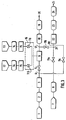
- Figure 1 is a flow diagram explaining how an apparatus according to the invention produces standard gas mixtures.
- FIGS 2 and 3 are two other embodiments of the invention.
- FIG. 1 is a flow diagram illustrating how an apparatus according to the invention operates to produce standard gas mixtures.
- raw gas source 1 is connected to pressure regulator 2, which in turn is coupled to purifier 3.
- the outlet port of purifier 3 is coupled to branching tube 4 which has two outlets ports.
- the first outlet port of tube 4 is connected to a needle valve 5.
- the needle valve 5 is connected to a mixing chamber 6.
- the second outlet port of tube 4 is coupled to a stop valve 9b, which in turn is connected to one of the two inlet ports of branching tube 10.
- Sample gas source 7 is connected to a pressure regulator 8.
- the pressure regulator 8 is coupled to a stop valve 9a.
- the stop valve 9a is connected to the other inlet port of the branching tube 10.
- the outlet port of this tube 10 is coupled to a needle valve 11a.
- a plurality of high-concentration standard gas mixture sources 12 and 13 are connected respectively to a pressure regulator 14, .
- These regulators 14 are coupled respectively to mass flow controllers 15, and mass flow controllers 15 are connected to a manifold 16 which can be an integrated valve (a double 3 ways valve as detailed for example in reference "Nikkei Microdevice, July 1987, challenge to ppt, T. Ohmi").
- the outlet port of the manifold 16 is connected to the mixing chamber 6.
- the outlet port of the mixing chamber 6 is coupled to the branching tube 17 having two outlets ports.
- the first outlet port of tube 17 is connected to back-pressure regulator 18, which in turn is coupled to flowmeter 19, which in turn is connected to a gas-discarding port. 20.
- the second outlet port of the branching tube 17 is coupled to a needle valve 11b.
- the valve 11b is connected to a branching tube 21 which connects the outlet of the needle valve 11a to an analytical instrument 22.
- the outlet port of the instrument 22 is coupled to a back-pressure regulator 23, which in turn is connected to a flowmeter 24, which in turn is connected to a gas-dicarding port 25.
- valves coupled to the lines connecting the gas sources of the apparatus described above When the valves coupled to the lines connecting the gas sources of the apparatus described above are operated selectively, various standard gas mixtures can be produced. It will be explained hereafter how this apparatus can realize the various functions referred to hereabove.
- the raw gas is supplied from material gas source 1 to the purifier 3 through the pressure regulator 2.
- Purifier 3 (such as two stages purifier system FP-S and FP-W, sold by Kinki Reinetsu K.K.) purifies the raw gas, thus forming a so called zero gas. Meanwhile, the sample gas is supplied from the sample gas source 7 to the pressure regulator 8.
- the high-concentration standard gas mixture is diluted first with the zero gas and then with the sample gas, generating a standard gas mixture which is suitable to draw calibration curves for use in both the internal standard method and the standard addition method, thus accomplishing function 2.
- valve 9a and the supply of high concentration gas mixture from manifold 16 is cut off there are three possible ways of implementing function 3, i.e. the introduction of zero gas (or blanc) into the analyzer :
- Function 4 Add to the zero gas calibrated amounts of gaseous species in order to generate controlled mixtures facilititating the calibration of the analyzing device ;
- This function can be carried out for example in one step or two steps :
- Function 5 Dilute in a controlled way the gas to be analyzed by the zero gas before introduction of the mixture into the analyzing device. This last point is particularly relevant for very polluted, or toxic and or corrosive gases.
- Closing 9b and opening 5, 11b, 11a and 9a allows to dilute the sample gas with the zero gas, thus realizing function 5.
- either the high-concentration standard gas mixture supplied from one source only or those from a plurality of sources such as 12 and 13, can be used to produce multiple standard gas mixtures.
- Fig. 2 is a second embodiment of the invention, the same device as those of fig. 1 bearing the same references.
- Valves 9a and 9b are replaced by restrictions 11a and 11c respectively, to control the pressure and the flowrate of the sample gas in combination with pressure regulators 8 and 23 as explained before and of the second portion of the high high purity diluent gas.
- a ratio of flowrates of each of these gases is fixed and cannot be modified without changing the characteristics of the restrictions.
- a mixture of those two gases is then made at the T-jonction 110, said mixture being diluted (or mixed) with the first flow of the medium concentration gas mixture coming from the needle valve 116.
- Figure 3 is another embodiment of the invention where the second portion of the high purity diluent gas is added through needle valve 11c to the mixture flowing from the outlet of the branching tube 21, but before introduction of the same in the analyzer 22.
- the apparatus according to the invention has multiple sources of high-concentration standard gas mixtures. Therefore, any possible combination of these gas mixtures can be used, merely by operating valves connected to the outlet ports of these gas mixture sources.
Landscapes
- Chemical & Material Sciences (AREA)
- Life Sciences & Earth Sciences (AREA)
- Engineering & Computer Science (AREA)
- Health & Medical Sciences (AREA)
- General Health & Medical Sciences (AREA)
- Pathology (AREA)
- Medicinal Chemistry (AREA)
- Physics & Mathematics (AREA)
- Analytical Chemistry (AREA)
- Biochemistry (AREA)
- Combustion & Propulsion (AREA)
- General Physics & Mathematics (AREA)
- Immunology (AREA)
- Food Science & Technology (AREA)
- Chemical Kinetics & Catalysis (AREA)
- Sampling And Sample Adjustment (AREA)
- Feeding, Discharge, Calcimining, Fusing, And Gas-Generation Devices (AREA)
- Accessories For Mixers (AREA)
- Medicines Containing Material From Animals Or Micro-Organisms (AREA)
- Breeding Of Plants And Reproduction By Means Of Culturing (AREA)
- Diaphragms For Electromechanical Transducers (AREA)
- Other Investigation Or Analysis Of Materials By Electrical Means (AREA)
Claims (24)
- Verfahren zum Erzeugen von Standardgasgemischen, umfassend die Schritte:- Steuern des Drucks eines Rohgases; daraufhin- Reinigen des Rohgases unter Erzeugen eines hochreinen Verdünnungsgases;- Steuern des Durchflusses von zumindest einem Standardgas hoher Konzentration;- Mischen des hochreinen Verdünnungsgases und des zumindest einen Standardgases hoher Konzentration unter Erzeugung eines Gasgemisches mittlerer Konzentration;- Aufteilen des Gasgemisches mittlerer Konzentration in einen ersten Strom und einen zweiten Strom;- Mischen des ersten Stroms mit einem Probengas oder dem Verdünnungsgas hoher Reinheit oder einem Gemisch daraus unter Gewinnen eines Standardgasgemisches niedriger Konzentration;- Steuern des Drucks des Probengases;- Steuern des Drucks des zweiten Stroms des Gasgemisches mittlerer Konzentration;- Steuern des Drucks des Standardgasgemisches niedriger Konzentration.
- Verfahren zum Erzeugen von Standardgasgemischen nach Anspruch 1, umfassend die folgenden zusätzlichen Schritte:- Aufteilen des Verdünnungsgases hoher Reinheit in einen ersten und einen zweiten Teil;- Mischen des ersten Teils des Verdünnungsgases hoher Reinheit und des zumindest einen Standardgases hoher Konzentration;- Verdünnen des ersten Stroms mit dem zweiten Teil des Verdünnungsgases hoher Reinheit.
- Verfahren zum Erzeugen von Standardgasgemischen nach Anspruch 1, umfassend den zusätzlichen Schritt:
- Verdünnen des ersten Gasstroms mit einem Probengas unter Gewinnen eines Standardgasgemisches niedriger Konzentration. - Verfahren zum Erzeugen von Standardgasgemischen nach Anspruch 1, umfassend die zusätzlichen Schritte:- Aufteilen des Verdünnungsgases hoher Reinheit in einen ersten und einen zweiten Teil;- Mischen des ersten Teils des Verdünnungsgases hoher Reinheit und des zumindest einen Standardgases hoher Konzentration;- Verdünnen des Probengases mit dem zweiten Teil des Verdünnungsgases hoher Reinheit, um ein verdünntes Probengas zu erzeugen;- Verdünnen des ersten Stroms mit dem verdünnten Probengas.
- Verfahren nach Anspruch 3, umfassend die zusätzlichen Schritte:- Teilen des Verdünnungsgases hoher Reinheit in einen ersten und einen zweiten Teil;- Mischen des ersten Teils des Verdünnungsgases hoher Reinheit und des zumindest einen Standardgases hoher Konzentration;- Verdünnen des Gasgemisches niedriger Konzentration mit dem zweiten Teil des Verdünnungsgases hoher Reinheit.
- Verfahren nach Anspruch 1, umfassend den Schritt eines vorübergehenden Einstellens der Zufuhr des Standardgases hoher Konzentration und des Probengases, um ein Verdünnungsgas hoher Reinheit als Standardgasgemisch zu erzeugen.
- Verfahren nach Anspruch 1, umfassend den Schritt eines vorübergehenden Einstellens der Zufuhr des Standardgases hoher Konzentration, um ein verdünntes Probengas als Standardgasgemisch zu erzeugen.
- Verfahren nach einem der Ansprüche 1 bis 7, umfassend den zusätzlichen Schritt, den Strom des Verdünnungsgases hoher Reinheit zu beschränken.
- Verfahren nach einem der Ansprüche 1 bis 8, umfassend den zusätzlichen Schritt, den ersten Strom des Gasgemisches mittlerer Konzentration zu beschränken.
- Verfahren nach einem der Ansprüche 1 bis 9, umfassend den zusätzlichen Schritt, den Strom des Probengases zu beschränken.
- Verfahren nach einem der Ansprüche 2 oder 4 bis 10, umfassend den zusätzlichen Schritt, den Strom des ersten Teils des Verdünnungsgases hoher Reinheit zu beschränken.
- Verfahren nach Anspruch 11, umfassend den zusätzlichen Schritt, den Strom des zweiten Teils des Verdünnungsgases hoher Reinheit zu beschränken.
- Verfahren nach einem der Ansprüche 1 bis 12, umfassend eine Mehrzahl aufeinanderfolgender Schritte, in denen der Strömungsbestandteil des Gasgemisches mittlerer Konzentration mit einem Teil des Verdünnungsgases hoher Reinheit gemischt wird, um ein weiteres Gasgemisch mittlerer Reinheit zu erzeugen, wobei der erste Strom des zuletzt genannten, zusätzlich erzeugten Gasgemisches mittlerer Konzentration zuletzt mit einem Probengas oder dem Verdünnungsgas oder einem Gemisch daraus gemischt wird, um ein Standardgasgemisch niedriger Konzentration zu erzeugen.
- Vorrichtung zum Erzeugen von Standardgasgemischen, mit:- einer Mehrzahl von Gasquellen einschließlich einer Quelle für Rohgas (1) und zwei oder mehr Quellen für Standardgase (12, 13) unterschiedlich hoher Konzentration;- einem Verteiler zum Sammeln der Standardgase (12, 13) hoher Konzentration von den Quellen für die Standardgase hoher Konzentration und zum Liefern eines Standardgasgemisches hoher Konzentration;- einer Quelle (7) für Probengas;- einer Probengasleitung, die mit der Quelle für das Probengas verbunden ist;- einer Einrichtung zum Steuern des Drucks (8) des Probengases (7);- einer Einrichtung zum Steuern des Drucks (2) des Rohgases (1), die stromaufwärts von einer Reinigungseinrichtung (3) zum Reinigen des Rohgases (1) angeordnet ist, das von der Quelle für Rohgas zum Erzeugen eines Verdünnungsgases hoher Reinheit zugeführt wird;- einer Einrichtung (4) zum Aufteilen des Verdünnungsgases hoher Reinheit in erste und zweite Teile, wobei der zweite Teil durch eine erste Drosseleinrichtung (5) strömt;- einer Mischeinrichtung (6) zum Mischen des ersten Teils des Verdünnungsgases hoher Reinheit mit dem Standardgasgemisch hoher Konzentration, das von dem Verteiler zugeführt wird, zur Erzeugung eines in etwa homogenen Gasgemisches mittlerer Konzentration;- einer Einrichtung (17) zum Aufteilen des Gasgemisches mittlerer Konzentration in einen ersten Strom und einen zweiten Strom, wobei der erste Strom durch eine zweite Drosseleinrichtung (llb) zugeführt wird;- einer Einrichtung (3b) zum Steuern des Durchflusses des zweiten Teils des Verdünnungsgases hoher Reinheit, wobei die Einrichtung eine Schließstellung hat, in der kein Gas strömt sowie eine Öffnungsstellung, in der der Durchfluß des Verdünnungsgases gesteuert werden kann;- einer Einrichtung (3a) zum Steuern des Durchflusses des Probengases, wobei die Einrichtung eine Schließstellung hat, in der kein Probengas strömt sowie eine Öffnungsstellung, in der der Durchfluß des Probengases gesteuert werden kann;- einer dritten Drosseleinrichtung (11a), die den zweiten Teil des Verdünnungsgases hoher Reinheit und/oder das Probengas aufnimmt und ein Verdünnungsgas erzeugt;- einer Einrichtung (21) zum Mischen des ersten Stroms des Gasgemisches mittlerer Konzentration und des Verdünnungsgases zur Erzeugung eines Standardgasgemisches niedriger Konzentration;- einer Einrichtung (18, 19) zum Steuern des Drucks des zweiten Stroms des Gasgemisches mittlerer Konzentration;- einer Einrichtung (22, 23, 24) zum Steuern des Drucks des Standardgasgemisches niedriger Konzentration.
- Vorrichtung zum Erzeugen von Standardgasgemischen nach Anspruch 14, zusätzlich umfassend eine Einrichtung (11) zum Absperren der Zufuhr des Gasgemisches hoher Konzentration.
- Vorrichtung nach Anspruch 14 oder 15, zusätzlich umfassend eine Drosseleinrichtung (5, 11a, 11b, 11c).
- Vorrichtung nach einem der Ansprüche 14 bis 16, zusätzlich umfassend eine Einrichtung zum Steuern des Drucks des Rohgases.
- Vorrichtung nach einem der Ansprüche 14 bis 17, zusätzlich umfassend eine Einrichtung zum Steuern des Drucks des Probengases.
- Vorrichtung nach einem der Ansprüche 14 bis 18, zusätzlich umfassend eine Einrichtung zum Steuern des Drucks des zweiten Stroms des Gasgemisches mittlerer Konzentration.
- Vorrichtung nach einem der Ansprüche 14 bis 19, zusätzlich umfassend eine Einrichtung zum Steuern des Drucks des Standardgasgemisches niedriger Konzentration.
- Vorrichtung nach einem der Ansprüche 14 bis 20, zusätzlich umfassend eine Einrichtung zum Steuern oder Absperren des Durchflusses des Probengases.
- Vorrichtung nach einem der Ansprüche 14 bis 21, zusätzlich umfassend eine Einrichtung zum Steuern oder Absperren des Durchflusses des zweiten Teils des Verdünnungsgases hoher Reinheit.
- Vorrichtung nach einem der Ansprüche 14 bis 22, wobei die Drosseleinrichtung eine kalibrierte Öffnung oder ein Nadelventil ist.
- Vorrichtung nach einem der Ansprüche 14 bis 23, zusätzlich umfassend eine Einrichtung zum Auslassen des zweiten Stroms des Gasgemisches mittlerer Konzentration.
Applications Claiming Priority (2)
| Application Number | Priority Date | Filing Date | Title |
|---|---|---|---|
| EP88402919A EP0370150A1 (de) | 1988-11-21 | 1988-11-21 | Verfahren zum Erzeugen eines Standardgasgemisches und Vorrichtung zu dessen Herstellung |
| EP88402919 | 1988-11-21 |
Publications (2)
| Publication Number | Publication Date |
|---|---|
| EP0370871A1 EP0370871A1 (de) | 1990-05-30 |
| EP0370871B1 true EP0370871B1 (de) | 1995-05-03 |
Family
ID=8200440
Family Applications (2)
| Application Number | Title | Priority Date | Filing Date |
|---|---|---|---|
| EP88402919A Withdrawn EP0370150A1 (de) | 1988-11-21 | 1988-11-21 | Verfahren zum Erzeugen eines Standardgasgemisches und Vorrichtung zu dessen Herstellung |
| EP89403154A Expired - Lifetime EP0370871B1 (de) | 1988-11-21 | 1989-11-17 | Verfahren zum Erzeugen eines Standardgasgemisches und Vorrichtung zu dessen Herstellung |
Family Applications Before (1)
| Application Number | Title | Priority Date | Filing Date |
|---|---|---|---|
| EP88402919A Withdrawn EP0370150A1 (de) | 1988-11-21 | 1988-11-21 | Verfahren zum Erzeugen eines Standardgasgemisches und Vorrichtung zu dessen Herstellung |
Country Status (10)
| Country | Link |
|---|---|
| US (1) | US5157957A (de) |
| EP (2) | EP0370150A1 (de) |
| JP (1) | JPH0721441B2 (de) |
| KR (1) | KR0153453B1 (de) |
| AT (1) | ATE122147T1 (de) |
| CA (1) | CA2003242A1 (de) |
| DE (1) | DE68922469T2 (de) |
| DK (1) | DK581189A (de) |
| FI (1) | FI895507A7 (de) |
| PT (1) | PT92357A (de) |
Families Citing this family (42)
| Publication number | Priority date | Publication date | Assignee | Title |
|---|---|---|---|---|
| US5056686A (en) * | 1989-06-27 | 1991-10-15 | Nutri-Fruit, Inc. | Beverage dispensing system |
| JPH0332191U (de) * | 1989-08-09 | 1991-03-28 | ||
| DE4012454C1 (de) * | 1990-04-19 | 1991-08-08 | Fraunhofer-Gesellschaft Zur Foerderung Der Angewandten Forschung E.V., 8000 Muenchen, De | |
| JPH0481650A (ja) * | 1990-07-25 | 1992-03-16 | Hitachi Ltd | 標準ガス調製装置 |
| FR2667397B1 (fr) * | 1990-10-02 | 1992-10-30 | Air Liquide | Procede et dispositif de fourniture de gaz a un analyseur a tres haute sensibilite. |
| US5239492A (en) * | 1990-10-11 | 1993-08-24 | Spacelabs Medical, Inc. | Automatic internal calibration circuit and method |
| US5199295A (en) * | 1991-01-22 | 1993-04-06 | Meeco, Inc. | Feedback controlled gas mixture generator especially for an hygrometer reaction check |
| US5214952A (en) * | 1991-08-16 | 1993-06-01 | Praxair Technology, Inc. | Calibration for ultra high purity gas analysis |
| WO1994002945A1 (en) * | 1992-07-17 | 1994-02-03 | Ionode Pty. Ltd. | Recalibrating apparatus and method |
| US5329804A (en) * | 1992-10-16 | 1994-07-19 | Abbott Laboratories | Calibration system and method for calibrating a blood gas sensor |
| FR2708995B1 (fr) * | 1993-08-12 | 1995-11-03 | Seres Ste Etud Real Equip Spec | Procédé et dispositif d'étalonnage continu pour la mesure de taux de gaz partiel dans l'air ambiant. |
| US5804695A (en) * | 1993-11-02 | 1998-09-08 | Horiba Instruments Incorporated | Gas dividing method and apparatus |
| US5457983A (en) * | 1994-08-23 | 1995-10-17 | Tecnovir International Inc. | Apparatus and method for producing a reference gas |
| EP0722789A1 (de) * | 1995-01-17 | 1996-07-24 | Elpatronic Ag | Verfahren zum Testen einer Funktion von einem Detektor in einer Inspektionsstation |
| US5611845A (en) * | 1995-08-22 | 1997-03-18 | Undersea Breathing Systems, Inc. | Oxygen enriched air generation system |
| US5756360A (en) * | 1995-09-29 | 1998-05-26 | Horiba Instruments Inc. | Method and apparatus for providing diluted gas to exhaust emission analyzer |
| US5624507A (en) * | 1995-12-29 | 1997-04-29 | Praxair Technology, Inc. | System for production of a quenchant gas mixture |
| US5661225A (en) * | 1996-09-12 | 1997-08-26 | Air Products And Chemicals, Inc. | Dynamic dilution system |
| FR2755512B1 (fr) * | 1996-11-05 | 1998-12-18 | Air Liquide | Procede et dispositif de fourniture a un appareil d'un gaz pur charge d'une quantite predeterminee d'au moins une impurete gazeuse |
| US5846831A (en) * | 1997-04-01 | 1998-12-08 | Horiba Instuments, Inc. | Methods and systems for controlling flow of a diluted sample and determining pollutants based on water content in engine exhaust emissions |
| US6349852B1 (en) | 1999-05-04 | 2002-02-26 | Bunn-O-Matic Corporation | Cold beverage refill system |
| US6964187B2 (en) * | 2001-03-20 | 2005-11-15 | Mykrolis Corporation | Vacuum sensor |
| DE10121458A1 (de) * | 2001-05-02 | 2002-11-14 | Siegfried Jahnke | Ein Verfahren zur routinemäßigen Kontrolle der Linearitäts- und Empfindlichkeitsparameter von Gasanalysatoren im Absolut- und Differenzmessbereich mittels einer Diffusionskammer |
| JP4195837B2 (ja) | 2003-06-20 | 2008-12-17 | 東京エレクトロン株式会社 | ガス分流供給装置及びガス分流供給方法 |
| GB2432711B (en) * | 2005-10-11 | 2008-04-02 | Gv Instr | Ion source preparation system |
| CN100458267C (zh) * | 2007-01-15 | 2009-02-04 | 同济大学 | 一种配气装置 |
| JP5054500B2 (ja) | 2007-12-11 | 2012-10-24 | 株式会社フジキン | 圧力制御式流量基準器 |
| CN102539202B (zh) * | 2010-12-30 | 2014-12-24 | 深圳光启高等理工研究院 | 一种亚硝酸乙酯标准气体的配制方法 |
| CN102539203A (zh) * | 2010-12-30 | 2012-07-04 | 深圳光启高等理工研究院 | 一种任意浓度亚硝酸乙酯标准气体的制备方法 |
| CN102564833B (zh) * | 2010-12-30 | 2015-02-04 | 深圳光启高等理工研究院 | 一种亚硝酸乙酯标准气体的配制方法 |
| US9592171B2 (en) | 2011-08-25 | 2017-03-14 | Undersea Breathing Systems, Inc. | Hyperbaric chamber system and related methods |
| EP2570179A1 (de) * | 2011-09-16 | 2013-03-20 | Air Liquide Deutschland GmbH | Verfahren und Vorrichtung zur dynamischen Gasgemisch Produktion |
| WO2013042024A1 (en) * | 2011-09-22 | 2013-03-28 | Koninklijke Philips Electronics N.V. | Method and apparatus for monitoring and controlling a pressure support device |
| CN102580590B (zh) * | 2012-03-01 | 2014-10-01 | 中国计量科学研究院 | 一种制备气体标准物质的微量转移系统及微量转移方法 |
| KR101407279B1 (ko) * | 2013-02-20 | 2014-06-13 | 국방과학연구소 | 미량의 농도를 가지는 독성가스 제조를 위한 가스 발생장치 및 이를 통한 가스 발생방법 |
| US9506898B1 (en) * | 2013-03-15 | 2016-11-29 | The United States Of America As Represented By The Secretary Of The Army | Device for controlled vapor generation |
| CN104297392B (zh) * | 2014-11-03 | 2015-12-30 | 常州宏福高端膦技术研发中心有限公司 | 检测磷化氢气体纯度的方法和装置 |
| TWI772330B (zh) | 2016-10-14 | 2022-08-01 | 荷蘭商蜆殼國際研究所 | 用於定量分析氣態製程流之方法及設備 |
| CN109781896B (zh) * | 2019-03-07 | 2022-06-17 | 西北大学 | 一种基于内标法的标准系列及气体样品的分析方法 |
| CN115753316A (zh) * | 2021-09-03 | 2023-03-07 | 中国石油化工股份有限公司 | 稀释气体的系统和方法 |
| CN115753317A (zh) * | 2021-09-03 | 2023-03-07 | 中国石油化工股份有限公司 | 用于气体配制的装置和方法 |
| CN118393087A (zh) * | 2024-06-19 | 2024-07-26 | 连云港市计量检定测试中心 | 便携式气体报警器多点校准装置及方法 |
Family Cites Families (18)
| Publication number | Priority date | Publication date | Assignee | Title |
|---|---|---|---|---|
| US3298383A (en) * | 1964-03-23 | 1967-01-17 | Phillips Petroleum Co | Fluid blending system |
| GB1364841A (en) * | 1971-08-12 | 1974-08-29 | British Oxygen Co Ltd | Fluid mixing |
| US3776023A (en) * | 1971-12-22 | 1973-12-04 | Monitor Labs Inc | Calibration system for gas analyzers |
| US3976450A (en) * | 1973-01-02 | 1976-08-24 | Roland Marcote | Gas sample preparation system and method |
| US3875499A (en) * | 1973-12-26 | 1975-04-01 | Gen Electric | Gas detection system |
| JPS52122184A (en) * | 1976-04-07 | 1977-10-14 | Yoshiichi Hashimoto | Standard dilution gas by using ph buffer solution* method and apparatus for preparation the same |
| US4142860A (en) * | 1976-06-23 | 1979-03-06 | Mayeaux Donald P | Apparatus for producing a calibration sample for analytical instrumentation |
| US4114419A (en) * | 1977-06-06 | 1978-09-19 | Kimbell Charles L | Method of testing an analyzer to determine the accuracy thereof and a volumetric primary standard apparatus for doing same |
| US4094187A (en) * | 1977-07-22 | 1978-06-13 | Champion International Corporation | Stack gas analyzing system with calibrating/sampling feature |
| US4164862A (en) * | 1977-11-25 | 1979-08-21 | Jackson Milton L | Multicomponent thermal conductivity analyzer |
| GB2036370B (en) * | 1978-09-22 | 1983-04-13 | Signal Instr | Maintaining total flow rate of combined fluid flows |
| US4290296A (en) * | 1979-11-16 | 1981-09-22 | Leco Corporation | Method and apparatus for gas dosing for linearization |
| US4314344A (en) * | 1980-01-31 | 1982-02-02 | Dasibi Environmental Corporation | Method and apparatus for generating selected gas concentrations |
| US4351614A (en) * | 1980-03-19 | 1982-09-28 | Eaton Corporation | Method of and apparatus for continually monitoring the heating value of a fuel gas using a combustibility meter |
| IT1144417B (it) * | 1981-07-22 | 1986-10-29 | Fiat Auto Spa | Apparecchiatura per la miscelazione controllata di due sostanze aeriformi in particolare per la preparazione di miscele per la taratura di a nalizzatori di gas di scarico di motori a combustione interna |
| JPS60143738A (ja) * | 1983-12-29 | 1985-07-30 | Shimadzu Corp | 標準水分含有ガス発生装置 |
| US4565086A (en) * | 1984-01-20 | 1986-01-21 | Baker Drilling Equipment Company | Method and apparatus for detecting entrained gases in fluids |
| EP0370151A1 (de) * | 1988-11-21 | 1990-05-30 | L'air Liquide, Societe Anonyme Pour L'etude Et L'exploitation Des Procedes Georges Claude | Verfahren zum Herstellen von Gasgemischen niedriger Konzentration und Vorrichtung zu ihrer Herstellung |
-
1988
- 1988-11-21 EP EP88402919A patent/EP0370150A1/de not_active Withdrawn
-
1989
- 1989-11-17 EP EP89403154A patent/EP0370871B1/de not_active Expired - Lifetime
- 1989-11-17 US US07/437,623 patent/US5157957A/en not_active Expired - Fee Related
- 1989-11-17 DE DE68922469T patent/DE68922469T2/de not_active Expired - Fee Related
- 1989-11-17 JP JP1299449A patent/JPH0721441B2/ja not_active Expired - Lifetime
- 1989-11-17 CA CA002003242A patent/CA2003242A1/en not_active Abandoned
- 1989-11-17 AT AT89403154T patent/ATE122147T1/de not_active IP Right Cessation
- 1989-11-17 FI FI895507A patent/FI895507A7/fi not_active Application Discontinuation
- 1989-11-20 PT PT92357A patent/PT92357A/pt not_active Application Discontinuation
- 1989-11-20 KR KR1019890016792A patent/KR0153453B1/ko not_active Expired - Fee Related
- 1989-11-20 DK DK581189A patent/DK581189A/da not_active Application Discontinuation
Also Published As
| Publication number | Publication date |
|---|---|
| CA2003242A1 (en) | 1990-05-21 |
| DE68922469T2 (de) | 1995-09-07 |
| DK581189A (da) | 1990-05-22 |
| JPH02276945A (ja) | 1990-11-13 |
| US5157957A (en) | 1992-10-27 |
| EP0370150A1 (de) | 1990-05-30 |
| ATE122147T1 (de) | 1995-05-15 |
| EP0370871A1 (de) | 1990-05-30 |
| FI895507A0 (fi) | 1989-11-17 |
| JPH0721441B2 (ja) | 1995-03-08 |
| FI895507A7 (fi) | 1990-05-22 |
| DK581189D0 (da) | 1989-11-20 |
| PT92357A (pt) | 1990-05-31 |
| KR0153453B1 (en) | 1998-11-16 |
| DE68922469D1 (de) | 1995-06-08 |
Similar Documents
| Publication | Publication Date | Title |
|---|---|---|
| EP0370871B1 (de) | Verfahren zum Erzeugen eines Standardgasgemisches und Vorrichtung zu dessen Herstellung | |
| US5239856A (en) | Apparatus for producing standard gas mixtures | |
| US5054309A (en) | Process for producing low-concentration gas mixtures, and apparatus for producing the same | |
| EP0528386B1 (de) | Kalibrierungssystem für die Analyse von ultrahoch reinen Gasen | |
| KR101016856B1 (ko) | 재료 혼합 시스템, 공정 시스템, 가스 시약 종류를 공급하도록 구성된 시스템, 가스 시약 종류 공급 시스템, 희석 반도체 제조 재료의 전달 시스템 및 희석 반도체 제조 재료의 전달 방법 | |
| JPH05180733A (ja) | 超高精度分析装置へのガス供給方法及び装置 | |
| IL187292A (en) | Method for manufacturing standard primary gas mixtures | |
| JPH0481650A (ja) | 標準ガス調製装置 | |
| GB2317231A (en) | Generating calibration gases for detectors | |
| JPH0843352A (ja) | ガス中の不純物の微量分析のための分析器へガスを供給するための方法および装置 | |
| US20030136176A1 (en) | Gas pressure/flow control and recovery system | |
| EP0370870B1 (de) | Verfahren zum Herstellen von Gasgemischen geringer Konzentration und Vorrichtung zu ihrer Erzeugung | |
| JP3280701B2 (ja) | 高感度分析器にガスを供給するための方法および装置 | |
| US6082398A (en) | Device for regulating the flow of gases having substantially different molar masses | |
| US4960568A (en) | Oxygen analyzer | |
| JP3670375B2 (ja) | 標準ガス希釈装置及び低濃度標準ガス発生装置 | |
| RU2208783C1 (ru) | Устройство для приготовления поверочных газовых смесей | |
| KR100244917B1 (ko) | 반도체설비의 부속기구 분석장치 및 이를 이용한 분석방법 |
Legal Events
| Date | Code | Title | Description |
|---|---|---|---|
| PUAI | Public reference made under article 153(3) epc to a published international application that has entered the european phase |
Free format text: ORIGINAL CODE: 0009012 |
|
| 17P | Request for examination filed |
Effective date: 19891123 |
|
| AK | Designated contracting states |
Kind code of ref document: A1 Designated state(s): AT BE CH DE ES FR GB IT LI LU NL SE |
|
| 17Q | First examination report despatched |
Effective date: 19930820 |
|
| GRAA | (expected) grant |
Free format text: ORIGINAL CODE: 0009210 |
|
| AK | Designated contracting states |
Kind code of ref document: B1 Designated state(s): AT BE CH DE ES FR GB IT LI LU NL SE |
|
| PG25 | Lapsed in a contracting state [announced via postgrant information from national office to epo] |
Ref country code: LI Effective date: 19950503 Ref country code: ES Free format text: THE PATENT HAS BEEN ANNULLED BY A DECISION OF A NATIONAL AUTHORITY Effective date: 19950503 Ref country code: CH Effective date: 19950503 Ref country code: BE Effective date: 19950503 Ref country code: AT Effective date: 19950503 |
|
| REF | Corresponds to: |
Ref document number: 122147 Country of ref document: AT Date of ref document: 19950515 Kind code of ref document: T |
|
| ITF | It: translation for a ep patent filed | ||
| REF | Corresponds to: |
Ref document number: 68922469 Country of ref document: DE Date of ref document: 19950608 |
|
| ET | Fr: translation filed | ||
| PG25 | Lapsed in a contracting state [announced via postgrant information from national office to epo] |
Ref country code: SE Effective date: 19950803 |
|
| REG | Reference to a national code |
Ref country code: CH Ref legal event code: PL |
|
| PG25 | Lapsed in a contracting state [announced via postgrant information from national office to epo] |
Ref country code: LU Free format text: LAPSE BECAUSE OF NON-PAYMENT OF DUE FEES Effective date: 19951130 |
|
| PLBE | No opposition filed within time limit |
Free format text: ORIGINAL CODE: 0009261 |
|
| STAA | Information on the status of an ep patent application or granted ep patent |
Free format text: STATUS: NO OPPOSITION FILED WITHIN TIME LIMIT |
|
| 26N | No opposition filed | ||
| PGFP | Annual fee paid to national office [announced via postgrant information from national office to epo] |
Ref country code: FR Payment date: 20011012 Year of fee payment: 13 |
|
| PGFP | Annual fee paid to national office [announced via postgrant information from national office to epo] |
Ref country code: GB Payment date: 20011019 Year of fee payment: 13 |
|
| PGFP | Annual fee paid to national office [announced via postgrant information from national office to epo] |
Ref country code: NL Payment date: 20011026 Year of fee payment: 13 |
|
| PGFP | Annual fee paid to national office [announced via postgrant information from national office to epo] |
Ref country code: DE Payment date: 20011029 Year of fee payment: 13 |
|
| REG | Reference to a national code |
Ref country code: GB Ref legal event code: IF02 |
|
| PG25 | Lapsed in a contracting state [announced via postgrant information from national office to epo] |
Ref country code: GB Free format text: LAPSE BECAUSE OF NON-PAYMENT OF DUE FEES Effective date: 20021117 |
|
| PG25 | Lapsed in a contracting state [announced via postgrant information from national office to epo] |
Ref country code: NL Free format text: LAPSE BECAUSE OF NON-PAYMENT OF DUE FEES Effective date: 20030601 |
|
| PG25 | Lapsed in a contracting state [announced via postgrant information from national office to epo] |
Ref country code: DE Free format text: LAPSE BECAUSE OF NON-PAYMENT OF DUE FEES Effective date: 20030603 |
|
| GBPC | Gb: european patent ceased through non-payment of renewal fee | ||
| PG25 | Lapsed in a contracting state [announced via postgrant information from national office to epo] |
Ref country code: FR Free format text: LAPSE BECAUSE OF NON-PAYMENT OF DUE FEES Effective date: 20030731 |
|
| NLV4 | Nl: lapsed or anulled due to non-payment of the annual fee |
Effective date: 20030601 |
|
| REG | Reference to a national code |
Ref country code: FR Ref legal event code: ST |
|
| PG25 | Lapsed in a contracting state [announced via postgrant information from national office to epo] |
Ref country code: IT Free format text: LAPSE BECAUSE OF NON-PAYMENT OF DUE FEES;WARNING: LAPSES OF ITALIAN PATENTS WITH EFFECTIVE DATE BEFORE 2007 MAY HAVE OCCURRED AT ANY TIME BEFORE 2007. THE CORRECT EFFECTIVE DATE MAY BE DIFFERENT FROM THE ONE RECORDED. Effective date: 20051117 |