EP0370876A1 - Vorrichtung zum Befestigen der Entmagnetisierungsspule eines Fernsehgeräts - Google Patents
Vorrichtung zum Befestigen der Entmagnetisierungsspule eines Fernsehgeräts Download PDFInfo
- Publication number
- EP0370876A1 EP0370876A1 EP89403169A EP89403169A EP0370876A1 EP 0370876 A1 EP0370876 A1 EP 0370876A1 EP 89403169 A EP89403169 A EP 89403169A EP 89403169 A EP89403169 A EP 89403169A EP 0370876 A1 EP0370876 A1 EP 0370876A1
- Authority
- EP
- European Patent Office
- Prior art keywords
- fixing
- loop
- foot
- ray tube
- hooks
- Prior art date
- Legal status (The legal status is an assumption and is not a legal conclusion. Google has not performed a legal analysis and makes no representation as to the accuracy of the status listed.)
- Granted
Links
Images
Classifications
-
- H—ELECTRICITY
- H01—ELECTRIC ELEMENTS
- H01J—ELECTRIC DISCHARGE TUBES OR DISCHARGE LAMPS
- H01J29/00—Details of cathode-ray tubes or of electron-beam tubes of the types covered by group H01J31/00
- H01J29/003—Arrangements for eliminating unwanted electromagnetic effects, e.g. demagnetisation arrangements, shielding coils
-
- H—ELECTRICITY
- H01—ELECTRIC ELEMENTS
- H01J—ELECTRIC DISCHARGE TUBES OR DISCHARGE LAMPS
- H01J2229/00—Details of cathode ray tubes or electron beam tubes
- H01J2229/0007—Elimination of unwanted or stray electromagnetic effects
- H01J2229/0046—Preventing or cancelling fields within the enclosure
- H01J2229/0053—Demagnetisation
Definitions
- the present invention relates to a device for fixing a television demagnetization loop.
- the subject of the present invention is a device for fixing a demagnetization loop of a cathode-ray tube of a television set, a device which is simple and inexpensive to produce, and which makes it possible to automate the optimal fixing of the loop, without requiring manual intervention during or after fixing, this device does not depend on the dimensions of the cathode ray tube.
- the demagnetization loop fixing device comprises, for each fixing point of the loop, a workpiece - support comprising at least one hook, workpiece support mounted free to rotate.
- the fixing points are preferably located near the four corners of the cathode ray tube slab.
- these four fixing points are the fixing screws of the cathode ray tube in the cabinet of the television set.
- the fixing devices are mounted to rotate freely on the head of the tube fixing screws.
- the support piece which is advantageously molded in plastic material, comprises two hooks formed on a cross member symmetrically with respect to the junction of this cross member with a support bracket whose foot comprises means allowing it to be fixed, free to rotate, at the attachment point of the loop.
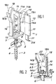
- the demagnetization loop fixing device 1 shown in the drawing is mounted on the head 2 of a screw 3 for fixing the cathode-ray tube (not shown).
- This screw 3 for example of the self-tapping type, passes through the hole of a fixing ear 4 (partially shown in FIG. 2) formed or welded on the anti-implosion belt of the cathode ray tube, and is screwed into a suitable location in the front of the TV.
- the anti-implosion belt has four such fixing ears located approximately on the diagonals of the slab of the cathode-ray tube on which it is placed.
- the head of a cathode ray tube fixing screw generally has the shape of a hexagonal block.
- this screw is modified as follows.
- This extension 7 has the shape of a grooved rod.
- the demagnetization loop fixing device proper consists essentially of a foot 9, a bracket 10 formed on the foot 9, a cross member 11 formed at the end of the bracket 10, two hook devices 12,13 formed at the ends of the cross member 11, and of a guide bar 14 formed on the foot 9. All of these elements of the device 1 are preferably made by molding of plastic material.
- the foot 9 has the shape of a substantially square plate whose central zone 15 is slightly convex (as seen from the stem 10), is circular in shape, has a reduced thickness, and has an axial hole whose diameter is substantially equal to the diameter of the part 7A of the extension 7.
- the area 15 of the foot 9 is split crosswise by two diametrical slots perpendicular to each other, thus delimiting four circular sectors.
- the zone 15 thus forms a retaining ring for fixing the device 1 to the extension 7 of the screw 3. It suffices to force the device 1 onto the extension 7, the grooves 8 causing the four circular sectors of the zone 15 to bend.
- the bracket 10 is formed in the middle of one of the sides of the foot 9, perpendicular to this foot.
- the cross member 11, formed at the end of the bracket 10, consists of two identical arms 11A, 11B arranged symmetrically with respect to the bracket 10, perpendicular to the latter.
- the hook devices 12, 13 each essentially comprise a body 16, 17, respectively, in the form of a rectangular bar, a hook 18, 19 respectively, formed at the end of the bar near its connection with the arm 11A, 11B, and a support tab 20,21, respectively, formed at the other end of the bar.
- the bars 16,17 are parallel to the bracket 10, directed towards the foot 9, and their length is substantially equal to that of the bracket 10.
- the bars 16,17 and the arms 11A, 11B are coplanar.
- the hooks 18,19 are in the form of folded tabs. These tongues comprise a flat part 18A, 19A connected by a bent part to the end of the corresponding bar 16, 17, on the side of the junction of the latter with the arm 11A, 11B respectively.
- the flat parts 18A, 19A make an angle of about 30 to 50 ° with the plane of the bars 16, 17, and are directed approximately towards the junction between the foot 9 and the bar 14.
- the length of the flat parts 18A, 19A is equal or slightly less than half the length of the bars 16,17.
- the respective dimensions of the flat parts 18A, 19A of the bars 16, 17 and the value of the angle formed between said flat parts and the bars are a function of the diameter of the cable 1A, forming the demagnetization loop, and of the space which is has in the cabinetry of the TV.
- the length of the bars 16.17 is approximately 25 mm
- the length of the flat parts 18A, 19A of approximately 10 mm and that of their angle relative to the plane of the bars 16.17 of approximately 40 ° for a 1A cable with a diameter of approximately 6 to 10 mm.
- the support tongues 20,21 are formed in the extension of the bars 16,17, their ends being bent at 90 ° opposite to the screw 3.
- the length of these tongues 20,21 is such that when the device 1 in place on the head 2 of the screw 3 and that this screw is screwed in place to fix the cathode ray tube, the ends 20A, 21A of these tongues are just in contact with the ear 4.
- the length of the bar 14 is substantially equal to that of the bars 16,17.
- This bar 14 has a first rectilinear part 14A parallel to the bracket 10, which extends approximately up to the height of the end 18B, 19B of the hooks 18,19, and a second part 14B, also rectilinear and parallel to the bracket 10, making an angle of about 10 to 20 ° with the first part, this second part deviating from the bracket 10.
- the junction between the parts 14A and 14B is referenced 14C.
- the narrowest part of this opening 22 is located between the junction 14C and the ends 18B, 19B of the parts 18A, 19A.
- the width L of this narrowest part is slightly less (about 1 to 3 mm) than the diameter of the cable lA.
- the loop demagnetization can be simply introduced by an automaton in these four fixing devices without having to be positioned with exactitude, and places itself in the correct position, that is to say symmetrically with respect to the a xes 0x, Oy of the screen, as close as possible to the anti-implosion belt, and with sufficient tension of the buckle.
- the parts 1 of the invention are standard whatever the type and size of the cathode ray tube, the fixing screws 3 being standard.
Landscapes
- Physics & Mathematics (AREA)
- Electromagnetism (AREA)
- Clamps And Clips (AREA)
- Devices For Indicating Variable Information By Combining Individual Elements (AREA)
- Video Image Reproduction Devices For Color Tv Systems (AREA)
- Formation Of Various Coating Films On Cathode Ray Tubes And Lamps (AREA)
Applications Claiming Priority (2)
| Application Number | Priority Date | Filing Date | Title |
|---|---|---|---|
| FR8815330 | 1988-11-24 | ||
| FR8815330A FR2639409B1 (fr) | 1988-11-24 | 1988-11-24 | Dispositif de fixation de boucle de demagnetisation de televiseur |
Publications (2)
| Publication Number | Publication Date |
|---|---|
| EP0370876A1 true EP0370876A1 (de) | 1990-05-30 |
| EP0370876B1 EP0370876B1 (de) | 1994-03-30 |
Family
ID=9372197
Family Applications (1)
| Application Number | Title | Priority Date | Filing Date |
|---|---|---|---|
| EP89403169A Expired - Lifetime EP0370876B1 (de) | 1988-11-24 | 1989-11-17 | Vorrichtung zum Befestigen der Entmagnetisierungsspule eines Fernsehgeräts |
Country Status (6)
| Country | Link |
|---|---|
| US (1) | US4971273A (de) |
| EP (1) | EP0370876B1 (de) |
| JP (1) | JPH02174485A (de) |
| DE (1) | DE68914258T2 (de) |
| FR (1) | FR2639409B1 (de) |
| HK (1) | HK25995A (de) |
Families Citing this family (4)
| Publication number | Priority date | Publication date | Assignee | Title |
|---|---|---|---|---|
| DE4000178A1 (de) * | 1989-01-18 | 1990-09-20 | Hermann Dipl Ing Walter | Vorrichtung zum befestigen von materialien auf metallstiften |
| US7835948B2 (en) * | 2006-09-07 | 2010-11-16 | The Golub Corporation | Floral network methods and systems for processing floral arrangements |
| US10132428B1 (en) * | 2017-07-19 | 2018-11-20 | Facebook, Inc. | Cable management clip |
| US12078271B2 (en) * | 2022-01-19 | 2024-09-03 | Diversitech Corporation | Brackets and methods of manufacture and use thereof |
Citations (5)
| Publication number | Priority date | Publication date | Assignee | Title |
|---|---|---|---|---|
| US3262662A (en) * | 1963-12-09 | 1966-07-26 | Raymond A | Cable fastener |
| US3643020A (en) * | 1970-03-09 | 1972-02-15 | Sylvania Electric Prod | Picture tube mounting means |
| FR2180067A1 (de) * | 1972-04-14 | 1973-11-23 | Tokyo Shibaura Electric Co | |
| DE8716945U1 (de) * | 1987-12-21 | 1988-02-25 | Lackdraht Union GmbH, 2838 Sulingen | Farbbildröhre mit Entmagnetisierungsspule |
| EP0281759A1 (de) * | 1987-02-12 | 1988-09-14 | EWD Electronic-Werke Deutschland GmbH | Einrichtung zur Halterung der Entmagnetisierungsspule an der Bildröhre |
Family Cites Families (6)
| Publication number | Priority date | Publication date | Assignee | Title |
|---|---|---|---|---|
| DE342688C (de) * | ||||
| US959076A (en) * | 1909-09-30 | 1910-05-24 | John T Scanlon | Trolley-wire hanger. |
| US1218181A (en) * | 1915-02-24 | 1917-03-06 | John W Homer | Insulator-knob. |
| US1585846A (en) * | 1921-11-14 | 1926-05-25 | Mid West Box Company | Mailing holder for phonograph records |
| FR930151A (fr) * | 1945-07-03 | 1948-01-19 | Detroit Harvester Co | Dispositif de fixation de pièces cylindriques, telles que condensateurs, fusibles, etc. |
| FR1366886A (fr) * | 1963-06-04 | 1964-07-17 | Raymond A | Attache permettant le montage d'objets tels que des câbles ou des tubes sur un support |
-
1988
- 1988-11-24 FR FR8815330A patent/FR2639409B1/fr not_active Expired - Fee Related
-
1989
- 1989-11-17 EP EP89403169A patent/EP0370876B1/de not_active Expired - Lifetime
- 1989-11-17 DE DE68914258T patent/DE68914258T2/de not_active Expired - Fee Related
- 1989-11-20 US US07/438,112 patent/US4971273A/en not_active Expired - Fee Related
- 1989-11-24 JP JP1306383A patent/JPH02174485A/ja active Pending
-
1995
- 1995-03-02 HK HK25995A patent/HK25995A/xx not_active IP Right Cessation
Patent Citations (5)
| Publication number | Priority date | Publication date | Assignee | Title |
|---|---|---|---|---|
| US3262662A (en) * | 1963-12-09 | 1966-07-26 | Raymond A | Cable fastener |
| US3643020A (en) * | 1970-03-09 | 1972-02-15 | Sylvania Electric Prod | Picture tube mounting means |
| FR2180067A1 (de) * | 1972-04-14 | 1973-11-23 | Tokyo Shibaura Electric Co | |
| EP0281759A1 (de) * | 1987-02-12 | 1988-09-14 | EWD Electronic-Werke Deutschland GmbH | Einrichtung zur Halterung der Entmagnetisierungsspule an der Bildröhre |
| DE8716945U1 (de) * | 1987-12-21 | 1988-02-25 | Lackdraht Union GmbH, 2838 Sulingen | Farbbildröhre mit Entmagnetisierungsspule |
Also Published As
| Publication number | Publication date |
|---|---|
| DE68914258T2 (de) | 1994-07-21 |
| DE68914258D1 (de) | 1994-05-05 |
| US4971273A (en) | 1990-11-20 |
| EP0370876B1 (de) | 1994-03-30 |
| FR2639409B1 (fr) | 1990-12-28 |
| FR2639409A1 (fr) | 1990-05-25 |
| JPH02174485A (ja) | 1990-07-05 |
| HK25995A (en) | 1995-03-10 |
Similar Documents
| Publication | Publication Date | Title |
|---|---|---|
| EP1080692A1 (de) | Anpassungsfähige Verbindung für Knochenverankerungsmittel | |
| WO2001011742A1 (fr) | Dispositif de guidage d'au moins un element longiligne souple, tel que cable ou autre, a contour substantiellement ferme | |
| FR2691415A1 (fr) | Dispositif de montage du genre rotule et élément intermédiaire, notamment pour réflecteur de projecteur de véhicule automobile. | |
| WO2007115622A1 (fr) | Dispositif de serrage | |
| FR2547372A1 (fr) | Dispositif de detection de la position d'un arbre dans un element d'accouplement notamment une machoire de joint de cardan | |
| EP0370876B1 (de) | Vorrichtung zum Befestigen der Entmagnetisierungsspule eines Fernsehgeräts | |
| EP0524879B1 (de) | Befestigungsvorrichtung für wenigstens zwei aufeinanderliegende Teile | |
| EP1531525B1 (de) | Kabelklemme mit vergrösserter Klemmfläche und damit ausgerüsteter Verbinderblock | |
| FR2767027A1 (fr) | Dispositif de prevention contre les volatiles | |
| EP0329515A1 (de) | Verbindungsstück, um einen Scheibenwischerblattbügel und einen Arm mit U-förmig gekrümmtem Ende zu verbinden | |
| FR2590633A1 (fr) | Dispositif de fixation reglable, en particulier pour l'assemblage d'ecrans video | |
| FR2747515A1 (fr) | Connecteur electrique et outil de pose d'agrafe pour un tel connecteur | |
| EP1538718B1 (de) | Spreizkrallenrückstelleinrichtung | |
| FR2562638A1 (fr) | Projecteur d'eclairage | |
| FR2759732A1 (fr) | Dispositif de transmission pour la manoeuvre d'un store | |
| FR2464570A1 (fr) | Borne de raccordement pour appareils electriques | |
| FR2716710A1 (fr) | Dispositif de fixation d'une source lumineuse dans un support de réception d'un projecteur. | |
| FR2524031A1 (fr) | Perfectionnements aux dispositifs d'ancrage destines a etre enfonces dans le sol | |
| FR2732083A1 (fr) | Dispositif de connexion a montage simplifie pour assembler deux profiles | |
| EP0307327A1 (de) | Schraubverbindungensvorrichtung für zwei Elemente mit der Möglichkeit den Abstand dazwischen einzustellen | |
| FR2711196A1 (fr) | Ecrou encagé à montage sur un rail ou analogue et assemblage obtenu à l'aide de cet écrou. | |
| CH310875A (fr) | Montre électrique à balancier moteur. | |
| EP1186837B1 (de) | Vorrichtung zur Wandbefestigung eines Heizkörpers und Verfahren zu dessen Befestigung | |
| EP0269539A2 (de) | Lösbare Schnellverbindung zwischen einer Glühbirne und ihrer Fassung | |
| FR2617652A1 (fr) | Groupe de branchement d'une lampe de signalisation |
Legal Events
| Date | Code | Title | Description |
|---|---|---|---|
| PUAI | Public reference made under article 153(3) epc to a published international application that has entered the european phase |
Free format text: ORIGINAL CODE: 0009012 |
|
| AK | Designated contracting states |
Kind code of ref document: A1 Designated state(s): DE GB IT |
|
| 17P | Request for examination filed |
Effective date: 19901008 |
|
| 17Q | First examination report despatched |
Effective date: 19921207 |
|
| RAP1 | Party data changed (applicant data changed or rights of an application transferred) |
Owner name: THOMSON TELEVISION ANGERS |
|
| GRAA | (expected) grant |
Free format text: ORIGINAL CODE: 0009210 |
|
| AK | Designated contracting states |
Kind code of ref document: B1 Designated state(s): DE GB IT |
|
| ITF | It: translation for a ep patent filed | ||
| REF | Corresponds to: |
Ref document number: 68914258 Country of ref document: DE Date of ref document: 19940505 |
|
| GBT | Gb: translation of ep patent filed (gb section 77(6)(a)/1977) |
Effective date: 19940609 |
|
| PLBE | No opposition filed within time limit |
Free format text: ORIGINAL CODE: 0009261 |
|
| STAA | Information on the status of an ep patent application or granted ep patent |
Free format text: STATUS: NO OPPOSITION FILED WITHIN TIME LIMIT |
|
| 26N | No opposition filed | ||
| PGFP | Annual fee paid to national office [announced via postgrant information from national office to epo] |
Ref country code: GB Payment date: 19961112 Year of fee payment: 8 |
|
| PGFP | Annual fee paid to national office [announced via postgrant information from national office to epo] |
Ref country code: DE Payment date: 19970122 Year of fee payment: 8 |
|
| PG25 | Lapsed in a contracting state [announced via postgrant information from national office to epo] |
Ref country code: GB Free format text: LAPSE BECAUSE OF NON-PAYMENT OF DUE FEES Effective date: 19971117 |
|
| GBPC | Gb: european patent ceased through non-payment of renewal fee |
Effective date: 19971117 |
|
| PG25 | Lapsed in a contracting state [announced via postgrant information from national office to epo] |
Ref country code: DE Free format text: LAPSE BECAUSE OF NON-PAYMENT OF DUE FEES Effective date: 19980801 |
|
| PG25 | Lapsed in a contracting state [announced via postgrant information from national office to epo] |
Ref country code: IT Free format text: LAPSE BECAUSE OF NON-PAYMENT OF DUE FEES;WARNING: LAPSES OF ITALIAN PATENTS WITH EFFECTIVE DATE BEFORE 2007 MAY HAVE OCCURRED AT ANY TIME BEFORE 2007. THE CORRECT EFFECTIVE DATE MAY BE DIFFERENT FROM THE ONE RECORDED. Effective date: 20051117 |