EP0371235B1 - Fraise-mère à lames rapportées - Google Patents
Fraise-mère à lames rapportées Download PDFInfo
- Publication number
- EP0371235B1 EP0371235B1 EP89118558A EP89118558A EP0371235B1 EP 0371235 B1 EP0371235 B1 EP 0371235B1 EP 89118558 A EP89118558 A EP 89118558A EP 89118558 A EP89118558 A EP 89118558A EP 0371235 B1 EP0371235 B1 EP 0371235B1
- Authority
- EP
- European Patent Office
- Prior art keywords
- screw
- toothed
- transverse grooves
- head
- cutting teeth
- Prior art date
- Legal status (The legal status is an assumption and is not a legal conclusion. Google has not performed a legal analysis and makes no representation as to the accuracy of the status listed.)
- Expired - Lifetime
Links
- 238000005520 cutting process Methods 0.000 claims abstract description 24
- 239000011248 coating agent Substances 0.000 abstract description 4
- 238000000576 coating method Methods 0.000 abstract description 4
- 230000036346 tooth eruption Effects 0.000 abstract 5
- 238000000034 method Methods 0.000 abstract 1
- 238000009434 installation Methods 0.000 description 2
- ATJFFYVFTNAWJD-UHFFFAOYSA-N Tin Chemical compound [Sn] ATJFFYVFTNAWJD-UHFFFAOYSA-N 0.000 description 1
- 230000001154 acute effect Effects 0.000 description 1
- 238000004026 adhesive bonding Methods 0.000 description 1
- 210000000481 breast Anatomy 0.000 description 1
- 230000003749 cleanliness Effects 0.000 description 1
- 230000006378 damage Effects 0.000 description 1
- 210000004283 incisor Anatomy 0.000 description 1
- 238000004519 manufacturing process Methods 0.000 description 1
- 238000003801 milling Methods 0.000 description 1
Images
Classifications
-
- B—PERFORMING OPERATIONS; TRANSPORTING
- B23—MACHINE TOOLS; METAL-WORKING NOT OTHERWISE PROVIDED FOR
- B23F—MAKING GEARS OR TOOTHED RACKS
- B23F21/00—Tools specially adapted for use in machines for manufacturing gear teeth
- B23F21/12—Milling tools
- B23F21/16—Hobs
- B23F21/163—Hobs with inserted cutting elements
- B23F21/166—Hobs with inserted cutting elements in exchangeable arrangement
Definitions
- the invention relates to a stud hob for the production of gears in the gear cutting process according to the preamble of claim 1.
- the stud hobbing cutters are provided with comb-like cutting tooth studs which can be inserted into the transverse grooves of a cylindrical base body, the individual tooth heads of which form a screw-line arrangement above the base body, the cutting tooth studs being held in the transverse grooves by means of clamping devices on the stud holding webs between the transverse grooves and held on both sides by means of end rings in the base body.
- grub screws are used here as clamping means, which can be screwed in at an acute angle against pockets inserted in the foot region of the toothed lugs for bracing them.
- the screw-in wrench makes it easy to get into the area of the tooth tips, which leads to difficult operability with a tightening that is too weak or if the grub screws are tightened too much, the Allen wrenches are easily damaged due to insufficient wall thickness and are no longer closed to open.
- DE-PS 593 531 shows bolts or clamps held by screws for holding the cutting tooth lugs, which have to withstand the changing high cutting forces and must not loosen, which is difficult to achieve in practice.
- FR-PS 1 455 182 also shows clamping screws that can be screwed in at an angle to the breast of the cutting tooth studs; however, these tend to loosen the changing high cutting forces acting on them in the same direction.
- the tight fit of the cutting tooth lugs in the transverse grooves on the base body to absorb the cutting forces is achieved, for example, by shrinking, gluing, wedging or pinning.
- the solution to disassembly into the individual parts requires great effort and is sometimes only possible by destruction.
- the assembly for reuse if possible at all, takes a considerable amount of time and the accuracy is reduced.
- the milling cutter was resharpened until it reached its final state.
- the stud hob is characterized according to the preamble of claim 1, characterized in that Allen screws - when tightening on the one hand with a sector of the lower edge of their screw head on the pocket bottom in the foot region of a stud back and on the other hand with their head circumference along a generatrix of the front of the adjacent stud foot issue.
- Allen screws - when tightening on the one hand with a sector of the lower edge of their screw head on the pocket bottom in the foot region of a stud back and on the other hand with their head circumference along a generatrix of the front of the adjacent stud foot issue.
- the stud bolts can each be screwed into a blind hole in the base body running parallel to this, with the spacing between the screw axis and the front side corresponding to the radius of the screw head. This enables unhindered removal and screwing in of the screws with automatic turning tools with adjustable torque and good accessibility.
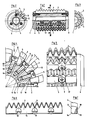
- the stud hob consists of a cylindrical base body 1 with transverse grooves 2, into which the comb-like cutting tooth studs 3 are inserted, the individual tooth heads 4 of which above the base body 1 according to FIG. 1 result in a helical arrangement.
- the cutting tooth studs 3 are clamped in the transverse grooves 2 by means of screwing means on the stud holding webs 5 and axially held on both sides in the ⁇ -area by means of screwed-on end rings 6 in the base body 1.
- Allen screws 7 serve as clamping means, which, when tightened, on the one hand with a sector of the lower edge 8 of a screw head 9 onto the pocket bottom 10 in the foot region 11 of a stud 3 and on the other hand with their head circumference along a generatrix 12 rest against the front 13 of the adjacent stud foot 14.
- the screw bolts 15 can each be screwed into a blind hole 16 running parallel thereto in the base body 1.
- the distance a between the screw axis and the front 13 corresponds to the screw head radius.
- ring grooves 17 are inserted, which receive the screw heads 9 recessed in the base body.
- the ring grooves 17 form at the inlet in the transverse groove 2 shoulders 18 and thus do not quite correspond to the transverse groove depth 2.
- the cutting tooth lugs 3 each have rounded pockets in the foot region 14 with bottom surfaces 10, as can be seen in FIGS. 6 and 7, for the installation of a sector of the Corresponding lower edge 8 of the screw head and, subsequently, obliquely recessed curves 19 for the screw bolt passage 15.
- the pockets with bottom surfaces 10 and the oblique curves 19 are worked with lateral air for the screw heads 8 and screw bolts 15 in order to avoid incorrect installation here.
- the transverse grooves 2 are perpendicular to the cutting direction, i.e. they (2) run in the longitudinal direction in the base body 1 and the ring grooves 17 run perpendicular to this, i.e. in the cutting direction.
Landscapes
- Engineering & Computer Science (AREA)
- Mechanical Engineering (AREA)
- Gear Processing (AREA)
- Table Equipment (AREA)
- Polishing Bodies And Polishing Tools (AREA)
- Knives (AREA)
- Dental Preparations (AREA)
- Luminescent Compositions (AREA)
- Organic Low-Molecular-Weight Compounds And Preparation Thereof (AREA)
- Pretreatment Of Seeds And Plants (AREA)
Claims (5)
Priority Applications (1)
| Application Number | Priority Date | Filing Date | Title |
|---|---|---|---|
| AT89118558T ATE80821T1 (de) | 1988-10-28 | 1989-10-06 | Stollenwaelzfraeser. |
Applications Claiming Priority (2)
| Application Number | Priority Date | Filing Date | Title |
|---|---|---|---|
| DE8813541U DE8813541U1 (de) | 1988-10-28 | 1988-10-28 | Stollenwälzfräser |
| DE8813541U | 1988-10-28 |
Publications (3)
| Publication Number | Publication Date |
|---|---|
| EP0371235A2 EP0371235A2 (fr) | 1990-06-06 |
| EP0371235A3 EP0371235A3 (en) | 1990-06-13 |
| EP0371235B1 true EP0371235B1 (fr) | 1992-09-23 |
Family
ID=6829350
Family Applications (1)
| Application Number | Title | Priority Date | Filing Date |
|---|---|---|---|
| EP89118558A Expired - Lifetime EP0371235B1 (fr) | 1988-10-28 | 1989-10-06 | Fraise-mère à lames rapportées |
Country Status (4)
| Country | Link |
|---|---|
| EP (1) | EP0371235B1 (fr) |
| AT (1) | ATE80821T1 (fr) |
| DE (2) | DE8813541U1 (fr) |
| ES (1) | ES2035493T3 (fr) |
Families Citing this family (6)
| Publication number | Priority date | Publication date | Assignee | Title |
|---|---|---|---|---|
| DE4219650A1 (de) * | 1992-06-16 | 1993-12-23 | Schmid Jakob Gmbh & Co | Vorrichtung zum Zerspanen von Holz oder holzartigen Werkstoffen |
| DE4445910C1 (de) * | 1994-12-22 | 1996-01-25 | Fette Wilhelm Gmbh | Wälzfräser |
| DE202015004072U1 (de) | 2015-06-11 | 2016-09-14 | Johne & Co. Präzisionswerkzeuge GmbH | Wälzfräszähne-Halter, Wälzfräswerkzeug und Bausatz zum Zusammenbauen eines Wälzfräswerkzeugs |
| DE102016214701B4 (de) | 2016-08-08 | 2020-09-10 | Verwaltungs-GbR (vertretungsberechtigte Gesellschafter: Peter Fischer, 68165 Mannheim; Dr. Markus Weiler, 76534 Baden-Baden; Waltraud Frick, 69214 Eppelheim) | Wälzfräser und Verfahren zur Herstellung eines Wälzfräsers |
| CN112727486B (zh) * | 2021-01-29 | 2023-03-31 | 安徽唐兴装备科技股份有限公司 | 一种盘形滚刀卡死安装结构及应用该结构的顶管机 |
| CN115341914A (zh) * | 2021-05-13 | 2022-11-15 | 中铁工程装备集团有限公司 | 一种矩形掘进机的摆动刀盘 |
Family Cites Families (8)
| Publication number | Priority date | Publication date | Assignee | Title |
|---|---|---|---|---|
| US1855511A (en) * | 1924-07-16 | 1932-04-26 | Barber Colman Co | Milling cutter |
| DE593531C (de) * | 1932-07-16 | 1934-02-28 | Artur Rehfeld | Fraeser mit eingesetzten Schneidplatten |
| DE1066072B (de) * | 1960-06-30 | 1959-09-24 | W. Ferd. Klingelnberg Söhne, Remscheid-Berghausen | Wälzfräser mit eingesetzten Zahnleisten |
| FR1455182A (fr) * | 1964-07-01 | 1966-04-01 | Marcoloy | Perfectionnements à des outils de coupe, taille, fraisage ou analogues et notammentà la fixation de ces outils |
| DE1959403U (de) * | 1967-02-24 | 1967-04-27 | Klingelnberg Soehne Ferd | Waelzfraeser. |
| GB1241950A (en) * | 1967-08-24 | 1971-08-04 | Donald William Allen | Milling cutter |
| FR2502999A1 (fr) * | 1981-04-03 | 1982-10-08 | Nanini Antoine | Fraise a plaquettes de coupe rapportees |
| DE8604712U1 (de) * | 1986-02-21 | 1986-11-20 | Wälztechnik Saacke-Zorn GmbH & Co KG, 7530 Pforzheim | Stollenwälzfräser |
-
1988
- 1988-10-28 DE DE8813541U patent/DE8813541U1/de not_active Expired
-
1989
- 1989-10-06 DE DE8989118558T patent/DE58902335D1/de not_active Expired - Fee Related
- 1989-10-06 ES ES198989118558T patent/ES2035493T3/es not_active Expired - Lifetime
- 1989-10-06 EP EP89118558A patent/EP0371235B1/fr not_active Expired - Lifetime
- 1989-10-06 AT AT89118558T patent/ATE80821T1/de not_active IP Right Cessation
Also Published As
| Publication number | Publication date |
|---|---|
| EP0371235A2 (fr) | 1990-06-06 |
| DE8813541U1 (de) | 1988-12-22 |
| DE58902335D1 (en) | 1992-10-29 |
| ES2035493T3 (es) | 1993-04-16 |
| EP0371235A3 (en) | 1990-06-13 |
| ATE80821T1 (de) | 1992-10-15 |
Similar Documents
| Publication | Publication Date | Title |
|---|---|---|
| DE2737537C2 (fr) | ||
| EP3694670B1 (fr) | Outil de taillage en développante | |
| EP2681000A1 (fr) | Filière | |
| EP0371235B1 (fr) | Fraise-mère à lames rapportées | |
| DE2736612A1 (de) | Wendeplatten-messerkopf | |
| DE2434041B2 (de) | Verstellbare mehrmesser-maschinenreibahle | |
| DE2533495B2 (de) | Bohrstange | |
| DE2802324A1 (de) | Bearbeitungswerkzeug | |
| DE8604712U1 (de) | Stollenwälzfräser | |
| DE9201113U1 (de) | Schneidplatte | |
| EP3292931B1 (fr) | Outil, notamment pour l'usinage de pièces à enlèvement de copeaux | |
| DE2542346B2 (de) | Innenraeumwerkzeug, insbesondere zur herstellung von profilnuten | |
| DE3211460A1 (de) | Zerspanungswerkzeug | |
| EP3477127A1 (fr) | Vis destinée à être vissée dans un trou de forage | |
| DE69603779T2 (de) | Hochpräzise Zentrierspitze | |
| DE10000330C2 (de) | Spanwinkelveränderliche Messerplatteneinspannung in Messerköpfen für die Holzbearbeitung | |
| DE19654815A1 (de) | Wendeschneidwerkzeug | |
| DE3130229C2 (de) | Mehrschneidenwerkzeug | |
| DE2633479A1 (de) | Stammblatt fuer ein diamantkreissaegeblatt | |
| DE202020103613U1 (de) | Mit zwei Drehmeißeln ausgestattete Lochsäge zum drehenden Lochschneiden | |
| DE2314197C3 (de) | Schneidwerkzeug für Drehmaschinen | |
| DE102020118981A1 (de) | Werkzeug zum Ein- und/oder Ausbau eines zapfenlosen Gewindeeinsatzes | |
| DE4116384A1 (de) | Form-schneidwerkzeug | |
| WO2007048467A1 (fr) | Porte-outil | |
| DE81568C (fr) |
Legal Events
| Date | Code | Title | Description |
|---|---|---|---|
| PUAI | Public reference made under article 153(3) epc to a published international application that has entered the european phase |
Free format text: ORIGINAL CODE: 0009012 |
|
| PUAL | Search report despatched |
Free format text: ORIGINAL CODE: 0009013 |
|
| AK | Designated contracting states |
Kind code of ref document: A2 Designated state(s): AT CH DE ES FR GB IT LI SE |
|
| AK | Designated contracting states |
Kind code of ref document: A3 Designated state(s): AT CH DE ES FR GB IT LI SE |
|
| 17P | Request for examination filed |
Effective date: 19900508 |
|
| 17Q | First examination report despatched |
Effective date: 19911217 |
|
| GRAA | (expected) grant |
Free format text: ORIGINAL CODE: 0009210 |
|
| AK | Designated contracting states |
Kind code of ref document: B1 Designated state(s): AT CH DE ES FR GB IT LI SE |
|
| PG25 | Lapsed in a contracting state [announced via postgrant information from national office to epo] |
Ref country code: SE Effective date: 19920923 Ref country code: GB Effective date: 19920923 |
|
| REF | Corresponds to: |
Ref document number: 80821 Country of ref document: AT Date of ref document: 19921015 Kind code of ref document: T |
|
| PG25 | Lapsed in a contracting state [announced via postgrant information from national office to epo] |
Ref country code: AT Effective date: 19921006 |
|
| PGFP | Annual fee paid to national office [announced via postgrant information from national office to epo] |
Ref country code: DE Payment date: 19921027 Year of fee payment: 4 |
|
| PGFP | Annual fee paid to national office [announced via postgrant information from national office to epo] |
Ref country code: FR Payment date: 19921028 Year of fee payment: 4 |
|
| REF | Corresponds to: |
Ref document number: 58902335 Country of ref document: DE Date of ref document: 19921029 |
|
| PG25 | Lapsed in a contracting state [announced via postgrant information from national office to epo] |
Ref country code: LI Effective date: 19921031 Ref country code: CH Effective date: 19921031 |
|
| ITF | It: translation for a ep patent filed | ||
| ET | Fr: translation filed | ||
| PGFP | Annual fee paid to national office [announced via postgrant information from national office to epo] |
Ref country code: ES Payment date: 19930128 Year of fee payment: 4 |
|
| GBV | Gb: ep patent (uk) treated as always having been void in accordance with gb section 77(7)/1977 [no translation filed] |
Effective date: 19920923 |
|
| REG | Reference to a national code |
Ref country code: ES Ref legal event code: FG2A Ref document number: 2035493 Country of ref document: ES Kind code of ref document: T3 |
|
| REG | Reference to a national code |
Ref country code: CH Ref legal event code: PL |
|
| PLBE | No opposition filed within time limit |
Free format text: ORIGINAL CODE: 0009261 |
|
| STAA | Information on the status of an ep patent application or granted ep patent |
Free format text: STATUS: NO OPPOSITION FILED WITHIN TIME LIMIT |
|
| 26N | No opposition filed | ||
| PG25 | Lapsed in a contracting state [announced via postgrant information from national office to epo] |
Ref country code: ES Free format text: LAPSE BECAUSE OF EXPIRATION OF PROTECTION Effective date: 19931007 |
|
| PG25 | Lapsed in a contracting state [announced via postgrant information from national office to epo] |
Ref country code: FR Effective date: 19940630 |
|
| PG25 | Lapsed in a contracting state [announced via postgrant information from national office to epo] |
Ref country code: DE Effective date: 19940701 |
|
| REG | Reference to a national code |
Ref country code: FR Ref legal event code: ST |
|
| REG | Reference to a national code |
Ref country code: ES Ref legal event code: FD2A Effective date: 19991007 |
|
| PG25 | Lapsed in a contracting state [announced via postgrant information from national office to epo] |
Ref country code: IT Free format text: LAPSE BECAUSE OF NON-PAYMENT OF DUE FEES;WARNING: LAPSES OF ITALIAN PATENTS WITH EFFECTIVE DATE BEFORE 2007 MAY HAVE OCCURRED AT ANY TIME BEFORE 2007. THE CORRECT EFFECTIVE DATE MAY BE DIFFERENT FROM THE ONE RECORDED. Effective date: 20051006 |