EP0371236B1 - Unité d'alimentation électrique - Google Patents
Unité d'alimentation électrique Download PDFInfo
- Publication number
- EP0371236B1 EP0371236B1 EP89118781A EP89118781A EP0371236B1 EP 0371236 B1 EP0371236 B1 EP 0371236B1 EP 89118781 A EP89118781 A EP 89118781A EP 89118781 A EP89118781 A EP 89118781A EP 0371236 B1 EP0371236 B1 EP 0371236B1
- Authority
- EP
- European Patent Office
- Prior art keywords
- supply unit
- power supply
- plug
- channel
- unit according
- Prior art date
- Legal status (The legal status is an assumption and is not a legal conclusion. Google has not performed a legal analysis and makes no representation as to the accuracy of the status listed.)
- Expired - Lifetime
Links
- 238000012544 monitoring process Methods 0.000 claims abstract description 3
- 238000012423 maintenance Methods 0.000 claims description 4
- 238000001816 cooling Methods 0.000 claims description 3
- 230000013011 mating Effects 0.000 claims description 2
- 238000003780 insertion Methods 0.000 description 30
- 230000037431 insertion Effects 0.000 description 30
- 239000000428 dust Substances 0.000 description 2
- 230000002349 favourable effect Effects 0.000 description 2
- 238000004804 winding Methods 0.000 description 2
- 230000008878 coupling Effects 0.000 description 1
- 238000010168 coupling process Methods 0.000 description 1
- 238000005859 coupling reaction Methods 0.000 description 1
- 230000002950 deficient Effects 0.000 description 1
- 238000011161 development Methods 0.000 description 1
- 230000018109 developmental process Effects 0.000 description 1
- 238000005516 engineering process Methods 0.000 description 1
- 238000012986 modification Methods 0.000 description 1
- 230000004048 modification Effects 0.000 description 1
- 230000001105 regulatory effect Effects 0.000 description 1
- 238000005096 rolling process Methods 0.000 description 1
- 239000004065 semiconductor Substances 0.000 description 1
Images

Classifications
-
- H—ELECTRICITY
- H02—GENERATION; CONVERSION OR DISTRIBUTION OF ELECTRIC POWER
- H02P—CONTROL OR REGULATION OF ELECTRIC MOTORS, ELECTRIC GENERATORS OR DYNAMO-ELECTRIC CONVERTERS; CONTROLLING TRANSFORMERS, REACTORS OR CHOKE COILS
- H02P4/00—Arrangements specially adapted for regulating or controlling the speed or torque of electric motors that can be connected to two or more different electric power supplies
-
- B—PERFORMING OPERATIONS; TRANSPORTING
- B23—MACHINE TOOLS; METAL-WORKING NOT OTHERWISE PROVIDED FOR
- B23Q—DETAILS, COMPONENTS, OR ACCESSORIES FOR MACHINE TOOLS, e.g. ARRANGEMENTS FOR COPYING OR CONTROLLING; MACHINE TOOLS IN GENERAL CHARACTERISED BY THE CONSTRUCTION OF PARTICULAR DETAILS OR COMPONENTS; COMBINATIONS OR ASSOCIATIONS OF METAL-WORKING MACHINES, NOT DIRECTED TO A PARTICULAR RESULT
- B23Q1/00—Members which are comprised in the general build-up of a form of machine, particularly relatively large fixed members
- B23Q1/0009—Energy-transferring means or control lines for movable machine parts; Control panels or boxes; Control parts
-
- B—PERFORMING OPERATIONS; TRANSPORTING
- B23—MACHINE TOOLS; METAL-WORKING NOT OTHERWISE PROVIDED FOR
- B23Q—DETAILS, COMPONENTS, OR ACCESSORIES FOR MACHINE TOOLS, e.g. ARRANGEMENTS FOR COPYING OR CONTROLLING; MACHINE TOOLS IN GENERAL CHARACTERISED BY THE CONSTRUCTION OF PARTICULAR DETAILS OR COMPONENTS; COMBINATIONS OR ASSOCIATIONS OF METAL-WORKING MACHINES, NOT DIRECTED TO A PARTICULAR RESULT
- B23Q11/00—Accessories fitted to machine tools for keeping tools or parts of the machine in good working condition or for cooling work; Safety devices specially combined with or arranged in, or specially adapted for use in connection with, machine tools
- B23Q11/0042—Devices for removing chips
- B23Q11/0046—Devices for removing chips by sucking
-
- B—PERFORMING OPERATIONS; TRANSPORTING
- B25—HAND TOOLS; PORTABLE POWER-DRIVEN TOOLS; MANIPULATORS
- B25F—COMBINATION OR MULTI-PURPOSE TOOLS NOT OTHERWISE PROVIDED FOR; DETAILS OR COMPONENTS OF PORTABLE POWER-DRIVEN TOOLS NOT PARTICULARLY RELATED TO THE OPERATIONS PERFORMED AND NOT OTHERWISE PROVIDED FOR
- B25F5/00—Details or components of portable power-driven tools not particularly related to the operations performed and not otherwise provided for
Definitions
- the invention relates to a power supply unit with a socket for at least one power tool with a brushless motor, in particular an asynchronous motor, which can be connected to it via a connecting cable, the power supply unit having a device for adjustable specification of the feed frequency.
- Such a power supply unit is known for example from DE-OS 37 09 983, DE-OS 37 22 177, DE-OS 37 26 262 and DE-GM 87 04 713.
- An adjustable frequency which is changed in relation to the mains voltage is used to drive an electric tool with such a motor, so that the power supply unit must have a corresponding frequency converter.
- Brushless motors, especially asynchronous motors have a stiffer and therefore more favorable torque / wire number characteristic, which means that the speed remains essentially constant as the motor load increases. The service life of the work equipment used is improved.
- there is a much cheaper power to weight ratio so that stronger, more compact power tools or hand machine tools can be manufactured.
- the disadvantage is that a power supply unit is always required as a separate device and must be carried when transporting the power tool.
- such a power supply unit is permanently installed in a vacuum cleaner, an output voltage with increased frequency being made available via a socket on the housing of the vacuum cleaner.
- the power tool can be plugged into this socket for power supply, with a suction hose for suction of chips, dust or the like. also connects the power tool to the vacuum cleaner.
- This arrangement has the disadvantage that the power supply unit can only be used in connection with the vacuum cleaner, that is to say that the vacuum cleaner must always be carried along, even when it is not required. The use for other power tools is therefore very limited.
- the power supply unit is designed as a slide-in device for various work tools that can be used in connection with the power tool and have at least one corresponding slide-in channel, a front housing wall of the power supply unit provided with the socket, control and monitoring elements essentially closing the slide-in opening of the slide-in channel when inserted.
- this power supply unit When used in combination, this power supply unit can be easily inserted into the respective work equipment, for example into a vacuum cleaner, and thereby forms a compact unit with it. On the other hand, this power supply unit can also be quickly pulled out and plugged into another piece of work equipment if this is necessary. In addition, independent use is also possible without any work equipment. Since such power supply units have a high price due to their complex technology, this variable use is of particular advantage. Due to the possibility of being pushed into different work tools, it can also be used for different types of power tools that are assigned to the respective work tools. It is also quick and easy to replace if the work equipment or the power supply unit is defective. The tools used in this way can be manufactured more cost-effectively, since only one insertion channel must be provided with an appropriate power supply.
- Guide elements on the power supply unit and preferably also on the insertion channel which cooperate, that is to say, for example, as profile grooves and correspondingly shaped profile strips engaging in them, have proven to be particularly useful.
- the power supply unit can be inserted precisely into the insertion channel and there is no risk of slipping or tilting.
- a secure positioning in the respective work equipment is achieved, with at least one fixing latching or holding element being able to be provided for additional securing.
- Such power supply units are provided with such a guide element on the underside and with a guide element serving as a counterpart at a corresponding position on the top side, then several power supply units can be mutually fixed one above the other.
- the same guide elements serve at the same time for fixing in the insertion channel of a work tool.
- At least one handle on the front housing wall proves to be particularly favorable.
- a cable winding device can also be arranged on the rear wall of the power supply unit or in the end region of the insertion channel, in which case a plug connection element is provided in the end region of the insertion channel or on the rear wall for connection to a plug connection element arranged at the cable end. This is done first by unwinding the cable and inserting the connector element the electrical connection is established, after which the cable is automatically wound up when the power supply unit is inserted into the insertion channel without the risk of this cable becoming jammed.
- a larger work tool for example a vacuum cleaner, a workshop trolley or a maintenance vehicle, can also have a plurality of insertion channels for accommodating a plurality of power supply units. This enables the simultaneous operation of several power tools via the work equipment.
- the implement is a vacuum cleaner, it expediently has a suction hose connection in the region of the insertion channel, preferably directly next to the socket of the inserted power supply unit. This enables parallel guidance of the suction hose and the electrical connecting line, which can preferably be mechanically coupled to one another.
- power supply units in work equipment such as cable drums, tool cases, wall brackets or wall housings for at least one power tool and for workshop trolleys or maintenance vehicles is also particularly advantageous.
- movable work equipment such as tool cases, workshop trolleys or the like
- these expediently have either a mains cable plug connection element, to which a loose mains cable can be connected, or in the case of a permanently connected mains cable, the latter is designed to be rolled up, the mains cable plug being expediently designed to be retractable in the work tool.
- the work equipment can be connected to the power grid very quickly and easily and disconnected again, the power cord no longer being a transport problem.
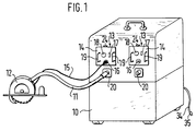
- a vacuum cleaner 10 is shown, via which a power tool 12 is connected in a manner known per se via a suction hose 11, which is designed as a portable circular saw in this embodiment.
- a power tool 12 is connected in a manner known per se via a suction hose 11, which is designed as a portable circular saw in this embodiment.
- suction hose 11 which is designed as a portable circular saw in this embodiment.
- other power tools can also be connected in which dust, chips or the like. should be suctioned off.
- two power supply units 13 are inserted in the upper region, specifically in correspondingly shaped insertion channels.
- a front plate 14 of the power supply units closes the insertion channel in the inserted state.
- the power supply units serve to supply the power tool 12, which is connected to the front plate 14 via a connecting cable 15 and a socket 16, with a supply voltage or a supply current of higher frequency for operating a brushless motor, in particular an asynchronous motor, in the power tool 12 a switch 14 and an adjusting device 18 for the speed are provided. Further and also alternative devices for setting, regulating and / or adapting the speed or frequency to the respective requirements can be designed in accordance with the stated prior art.
- Two handles 19 serve for easier insertion and removal of the power supply units from the vacuum cleaner.
- Suction connections 20 for the suction hose 11 are each arranged below the insertion channels for the power supply units 13 on the housing of the vacuum cleaner 10, and as close as possible to the sockets 16 in order to allow the suction hose 11 and the connecting cable 15 to be routed together to the power tool 12.
- the suction hose 11 and the connecting cable 15 can therefore also be designed as a uniform, combined connecting line.
- the power supply unit 13 shown on the right in the drawing is not connected to a power tool, but offers the possibility of connecting a similar or different power tool, such as a grinder, a planer, a jigsaw or the like, and to jointly via the vacuum cleaner operate. It is also possible to provide only a single or additional power supply units.
- its rear wall 21 has a rigid electrical connector element 22, with a corresponding mating connector element being provided at the corresponding point in the rear region of the insertion channel in the vacuum cleaner 10 (not visible in the drawing) is so that when the power supply unit is inserted into the vacuum cleaner 10, the power supply unit is automatically and automatically connected to the mains.
- a T-shaped profile strip 23 is provided as a guide element on the top of the power supply unit 13, which engages in a correspondingly shaped profile groove 24 above the insertion channel during insertion.
- Locking or locking elements can be used for additional locking of the inserted power supply unit.
- a foldable and in the power supply unit 13 in folded-down, sunk handle 25 is additionally arranged on the top of the power supply unit 13 to facilitate its transportation.
- the handle 25 encompasses the profile strip 23.
- a profile groove 26 corresponding to the profile of the profile strip 23 on the underside of the power supply unit 13 serves to connect a plurality of power supply units 13 to one another by inserting profile strips into these profile grooves 26 and to transport them together by means of the carrying handle 25.
- a correspondingly shaped profile strip can be provided on the underside of the insertion channel, which engages in this profile groove 26 when the power supply unit is inserted.
- the plug connection element 22 must be connected to a mains socket via a connecting cable.
- a permanently connected power cable with a retractor can also be provided on the rear wall of the power supply unit 13 or in the rear area of the insertion channels.
- this power cord is on the power supply unit 13 is provided, the electrical connection is first made by partially unrolling this power cable and plugging it into a corresponding socket in the rear area of the insertion channel, and then the power supply unit 13 can be inserted into the insertion channel, the cable automatically rolling up.
- the connection is made by unrolling a cable in the rear region of the insertion channel and by plugging it into the plug connection part 22.
- a retractor can also be dispensed with.
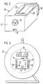
- the power supply unit 13 is inserted into a corresponding insertion channel in the central region of a cable drum 27.
- the mains supply for the power supply unit 13 can be produced in one of the ways described.
- Guide elements such as profile grooves and profile strips are recommended in any case, since in some versions of a cable drum 27 the power supply unit 13 rotates with the drum.
- this cable drum also provides a voltage with a variable, adjustable frequency for connecting power tools with brushless motors.
- the power supply unit 13 is inserted into a corresponding guide channel in a tool case 29.
- the tool case has compartments 30 for receiving small tools, screws, nails, washers or the like. as well as a larger compartment 31 for receiving an electric tool 32, which is designed here as a grinding device.
- a lid 33 is used to close the tool case 29.
- a power cable 34 on the outside of the tool case 29 can either be connected there, or there is a recessed winding device and a recess for receiving a plug 35 of the power cable 34.
- the power supply unit 13 can also be in a Side wall of the tool case 29 can be designed to be insertable. This has the advantage that the power tool 32 can be inserted even when the cover 30 is closed. Furthermore, it is also possible, while maintaining the attachment location shown in FIG. 4, to provide through openings 33 in the cover which allow access to the socket 16 or to other operating and / or control elements.
- one or more power supply units 13 can also be inserted into insertion channels of wall brackets and wall housings for power tools with a brushless motor or of workshop trolleys and maintenance vehicles, on or in which such power tools are transported, so that the corresponding power supply is ensured in a simple manner and damage to the power supply units can be largely prevented.
- Use in other similar work tools is of course also possible. It is essential here that the respective power supply units can be used in a variable manner either separately or in these work tools and can be used in a fixed and secured manner, a quick and simple exchange also being possible.
- the power supply unit contains electronic power components, in particular power semiconductor switches, for the heat sink are required.
- these heat sinks are preferably arranged on the front housing wall 14, that is to say on the front plate facing outwards. This can take place either in that these heat sinks are arranged on the inside of this front housing wall 14 and the housing wall itself is at least partially designed as a heat sink, that is to say provided with cooling fins, or in that the heat sinks protrude outwards through openings from this front housing wall 14 or attached to it from the outside.
Landscapes
- Engineering & Computer Science (AREA)
- Mechanical Engineering (AREA)
- Power Engineering (AREA)
- Electric Vacuum Cleaner (AREA)
- Vehicle Body Suspensions (AREA)
- Apparatus For Radiation Diagnosis (AREA)
- Input Circuits Of Receivers And Coupling Of Receivers And Audio Equipment (AREA)
- Control Of Ac Motors In General (AREA)
- Connector Housings Or Holding Contact Members (AREA)
- Motor Or Generator Frames (AREA)
Claims (13)
- Ensemble d'alimentation électrique (13), avec une prise femelle (16) pour au moins un outil électrique (12), à moteur sans balais, susceptible de lui être raccordé par l'intermédiaire d'un câble de liaison (15), le moteur étant en particulier un moteur asynchrone, l'ensemble d'alimentation électrique présentant un dispositif d'allocation réglable de la fréquence d'alimentation, caractérisé en ce que l'ensemble d'alimentation électrique (13) est réalisé sous forme d'appareil à encastrer pour différents réceptacles à outils (10, 27, 29) présentant au moins un canal d'encastrement correspondant, utilisables en liaison avec l'outil électrique (12, 32), une paroi de carter (14) avant, pourvue de la prise femelle (16), des éléments de commande et de contrôle (17, 18) de l'ensemble d'alimentation électrique (13), délimitant pour l'essentiel, à l'état encastré, l'ouverture d'encastrement du canal d'encastrement.
- Ensemble d'alimentation électrique selon la revendication 1, caractérisé en ce qu'il présente des éléments de guidage (23), coopérant avec des éléments de guidage (24) situés sur le canal d'encastrement ou avec des éléments de guidage (26) situés sur un autre ensemble d'alimentation électrique (13) correspondant, réalisés de préférence sous forme de rainures profilées (24, 26) et de bandes profilées, s'engageant dans celles-ci et ayant une forme correspondante.
- Ensemble d'alimentation électrique selon la revendication 2, caractérisé en ce qu'il est pourvu d'un élément de guidage (26) placé en face inférieure et d'un élément de guidage (23), servant de pièce conjuguée, situé en une position correspondante en face supérieure.
- Ensemble d'alimentation électrique selon la revendications 2 ou 3, caractérisé en ce qu'est prévu au moins un élément à cliquet ou élément de maintien, désolidarisable, assurant la fixation de l'ensemble d'alimentation électrique (13) à l'état encastré.
- Ensemble d'alimentation électrique selon l'une des revendications précédentes, caractérisé par une poignée de portage (25), rabattable et/ou escamotable, en face supérieure et/ou au moins une poignée de maintien (19), sur la paroi avant (14) du carter.
- Ensemble d'alimentation électrique selon l'une des revendications précédentes, caractérisé par un élément de liaison à enfichage (22) monté fixe, pour assurer l'alimentation par le réseau sur la paroi arrière (21) opposée à la paroi avant (14) du carter, un élément de liaison à enfichage conjugué, amenant la tension du réseau, s'accouplant électriquement à cet élément de liaison par enfichage (22), lorsque l'ensemble d'alimentation électrique est à l'état encastré, étant prévu dans la zone d'extrémité du canal d'encastrement.
- Ensemble d'alimentation électrique selon l'une des revendications 1 à 5, caractérisé en ce qu'un dispositif d'enroulement de câble est disposé sur sa paroi arrière (21) ou dans la zone d'extrémité du canal d'encastrement, et en ce que, dans la zone d'extrémité du canal d'encastrement ou sur la paroi arrière (21) est prévu un élément de liaison à enfichage, pour assurer la liaison avec un élément de liaison à enfichage disposé à l'extrémité de câble.
- Ensemble d'alimentation électrique selon l'une des revendications précédentes, caractérisé par plusieurs canaux d'encastrement, destinés à recevoir plusieurs ensembles d'alimentation électrique sur un réceptacle à outils.
- Ensemble d'alimentation électrique selon l'une des revendications précédentes, caractérisé en ce que le réceptacle à outils (10) est un aspirateur à poussière, un raccordement pour tuyau d'aspiration (20) étant disposé dans la zone du canal d'encastrement, de préférence directement à côté de la prise femelle (16) de l'ensemble d'alimentation électrique (13).
- Ensemble d'alimentation électrique selon l'une des revendications 1 à 8, caractérisé en ce que le réceptacle à outils (27) est un tambour à câble, en ce que le canal d'encastrement est disposé dans la zone centrale du tambour à câble et en ce que, de préférence, au moins une prise femelle (28) est disposée à côté du canal d'encastrement.
- Ensemble d'alimentation électrique selon l'une des revendications 1 à 8, caractérisé en ce que le réceptacle à outils (29) est un coffre à outils, une fixation murale, un carter mural, pour au moins un outil électrique (32), avec un moteur sans balai, un chariot d'atelier ou un véhicule d'entretien, et en ce qu'il est de préférence encastrable dans une paroi extérieure latérale du réceptacle à outils.
- Ensemble d'alimentation électrique selon l'une des revendications précédentes, caractérisé en ce que le réceptacle à outils (10, 29) est pourvu d'un câble de raccordement au réseau (34), en particulier enroulable, ou d'un élément de liaison à enfichage pour câble de réseau, la prise mâle (35) de câble de réseau étant de préférence réalisée escamotable dans le réceptacle à outils (10, 29).
- Ensemble d'alimentation électrique selon l'une des revendications précédentes, caractérisé en ce que des corps de refroidissement, nécessaires pour assurer le refroidissement de composants de puissance électroniques, sont disposés sur la paroi avant (14) du carter, les composants de puissance étant de préférence reliés, par l'intermédiaire de ponts thermiques, à la face intérieure de la paroi avant (14) du carter, réalisée au moins partiellement sous forme de corps de refroidissement, et les corps de refroidissement passant à travers des ouvertures ménagées dans la paroi avant (14) du carter, en sortant de l'ensemble d'alimentation électrique, ou fixés en face extérieure de la paroi avant (14) du carter.
Priority Applications (1)
| Application Number | Priority Date | Filing Date | Title |
|---|---|---|---|
| AT89118781T ATE104484T1 (de) | 1988-11-26 | 1989-10-10 | Stromversorgungseinheit. |
Applications Claiming Priority (2)
| Application Number | Priority Date | Filing Date | Title |
|---|---|---|---|
| DE3839932 | 1988-11-26 | ||
| DE3839932A DE3839932A1 (de) | 1988-11-26 | 1988-11-26 | Stromversorgungseinheit |
Publications (3)
| Publication Number | Publication Date |
|---|---|
| EP0371236A2 EP0371236A2 (fr) | 1990-06-06 |
| EP0371236A3 EP0371236A3 (fr) | 1991-12-11 |
| EP0371236B1 true EP0371236B1 (fr) | 1994-04-13 |
Family
ID=6367926
Family Applications (1)
| Application Number | Title | Priority Date | Filing Date |
|---|---|---|---|
| EP89118781A Expired - Lifetime EP0371236B1 (fr) | 1988-11-26 | 1989-10-10 | Unité d'alimentation électrique |
Country Status (3)
| Country | Link |
|---|---|
| EP (1) | EP0371236B1 (fr) |
| AT (1) | ATE104484T1 (fr) |
| DE (2) | DE3839932A1 (fr) |
Families Citing this family (15)
| Publication number | Priority date | Publication date | Assignee | Title |
|---|---|---|---|---|
| DE29806182U1 (de) | 1998-04-03 | 1998-06-18 | Wacker Werke GmbH & Co. KG, 80809 München | Kabeltrommel mit integrierter Saugluftquelle |
| DE19816684C2 (de) * | 1998-04-15 | 2001-06-28 | Hilti Ag | Elektrowerkzeug mit separater Stromversorgungseinheit |
| US7058291B2 (en) | 2000-01-07 | 2006-06-06 | Black & Decker Inc. | Brushless DC motor |
| US6538403B2 (en) | 2000-01-07 | 2003-03-25 | Black & Decker Inc. | Brushless DC motor sensor control system and method |
| US6975050B2 (en) | 2000-01-07 | 2005-12-13 | Black & Decker Inc. | Brushless DC motor |
| DE10132831A1 (de) * | 2001-07-06 | 2003-01-16 | Bosch Gmbh Robert | Koffer mit einer Aufnahmebucht für ein akkubetriebenes Elektrowerkzeug sowie Koffersystem mit mindestens zwei solchen Koffern |
| DE10139979B4 (de) * | 2001-08-21 | 2006-09-07 | Tts Tooltechnic Systems Ag & Co. Kg | Werkzeugkoffer |
| DE10145583A1 (de) * | 2001-09-15 | 2003-04-03 | Bosch Gmbh Robert | Handwerkzeugmaschine mit Staubbox |
| ES2295286T3 (es) * | 2001-12-21 | 2008-04-16 | Guido Valentini | Recipiente portatil para una herramienta electrica con capacidad de aspiracion y recogida de polvo. |
| DE102005023880A1 (de) * | 2005-05-24 | 2006-11-30 | Wacker Construction Equipment Ag | Drehzahlmessung und -regelung für einen Universalmotor |
| DE102011083319A1 (de) * | 2011-09-23 | 2013-03-28 | Robert Bosch Gmbh | Werkzeugzusatzgerät |
| US9055033B2 (en) | 2012-07-17 | 2015-06-09 | Milwaukee Electric Tool Corporation | Universal protocol for power tools |
| EP4585372A3 (fr) | 2017-07-05 | 2025-07-30 | Milwaukee Electric Tool Corporation | Adaptateurs pour communication entre des outils électriques |
| US11011053B2 (en) | 2018-07-31 | 2021-05-18 | Tti (Macao Commercial Offshore) Limited | Systems and methods for remote power tool device control |
| WO2022177905A1 (fr) | 2021-02-16 | 2022-08-25 | Milwaukee Electric Tool Corporation | Communication entre un extracteur de poussière sans fil et un outil électrique |
Family Cites Families (12)
| Publication number | Priority date | Publication date | Assignee | Title |
|---|---|---|---|---|
| DE1266377B (de) * | 1966-06-10 | 1968-04-18 | Siemens Ag | Anordnung von Geraeten der elektrischen Nachrichtentechnik, insbesondere der Richtfunktechnik |
| US3513478A (en) * | 1968-10-24 | 1970-05-19 | Kustom Kreations Inc | Multiple purpose removable electrical mounting bracket |
| DE6945656U (de) * | 1969-11-18 | 1970-03-19 | Loewe Opta Gmbh | Gehaeuse fuer elektrische geraete mit batteriebetrieb |
| US3614459A (en) * | 1970-11-20 | 1971-10-19 | Fred A Watson | Vehicular remote power supply system |
| US3676694A (en) * | 1971-06-04 | 1972-07-11 | Modern Ind Inc | Power output accessory unit |
| DE3323464A1 (de) * | 1982-07-07 | 1984-02-09 | ACM Endoscopie GmbH, 8000 München | Geraet zur stromversorgung |
| DE3482617D1 (de) * | 1984-08-14 | 1990-08-02 | Rudolf Reinhardt | Gehaeuse fuer die aufnahme elektrischer bauelemente. |
| DE3504079A1 (de) * | 1985-02-07 | 1986-08-14 | Philips Patentverwaltung Gmbh, 2000 Hamburg | Geraeteeinsatz der nachrichtentechnik |
| WO1988002593A1 (fr) * | 1986-09-30 | 1988-04-07 | Standard Electric Puhelinteollisuus Oy | Rack secondaire pivotant pour dispositif electronique |
| DE3643558A1 (de) * | 1986-12-19 | 1988-07-07 | Wolf Geraete Gmbh | Elektromotorisches antriebssystem |
| DE8702066U1 (de) * | 1987-02-11 | 1987-05-14 | Euroatlas GmbH für Umformertechnik und Optronik, 2800 Bremen | Stromversorgungsgerät in Einschubbauweise |
| DE8704713U1 (de) * | 1987-03-31 | 1987-08-13 | Zubler Gerätebau GmbH, 7910 Neu-Ulm | Industriesauger mit integriertem Umrichter zur Versorgung von Handwerkzeugen |
-
1988
- 1988-11-26 DE DE3839932A patent/DE3839932A1/de not_active Withdrawn
-
1989
- 1989-10-10 EP EP89118781A patent/EP0371236B1/fr not_active Expired - Lifetime
- 1989-10-10 DE DE58907456T patent/DE58907456D1/de not_active Expired - Fee Related
- 1989-10-10 AT AT89118781T patent/ATE104484T1/de not_active IP Right Cessation
Also Published As
| Publication number | Publication date |
|---|---|
| EP0371236A2 (fr) | 1990-06-06 |
| DE3839932A1 (de) | 1990-05-31 |
| DE58907456D1 (de) | 1994-05-19 |
| EP0371236A3 (fr) | 1991-12-11 |
| ATE104484T1 (de) | 1994-04-15 |
Similar Documents
| Publication | Publication Date | Title |
|---|---|---|
| EP0371236B1 (fr) | Unité d'alimentation électrique | |
| DE69936240T2 (de) | Schnurloses elektrisches Werkzeugsystem | |
| DE112015003376C5 (de) | Elektrisch angetriebene Kettensäge | |
| DE19737424C1 (de) | Werkzeugkoffer mit mindestens einer Kabelrolle | |
| DE112013007758B3 (de) | Handgehaltene elektrische Schneidvorrichtung | |
| DE112015001742B4 (de) | Elektrisches Kraftwerkzeug | |
| DE3900577C2 (fr) | ||
| DE112013006568T5 (de) | Elektrisches Werkzeug | |
| DE102016201802A1 (de) | Handwerkzeugmaschine | |
| EP2996174A1 (fr) | Boitier de chargeur d'accumulateurs pour appareil electrique | |
| DE29618127U1 (de) | Elektrisches Poliergerät | |
| DE102019102360A1 (de) | Langstabpoliervorrichtung | |
| DE29618131U1 (de) | Elektrowerkzeug | |
| EP3229337B1 (fr) | Chargeur | |
| DE10064173C1 (de) | Bohrmaschine mit Elektromotor für Gesteinsbohrer | |
| DE102018119234A1 (de) | Wiederaufladbare Kraftwerkzeuge | |
| DE102016205568A1 (de) | Handwerkzeugmaschine und Akkupack für eine Handwerkzeugmaschine | |
| EP1414625B1 (fr) | Coffret dote d'un logement destine a un outil electrique a accumulateurs et systeme coffret comportant au moins deux coffrets de ce type | |
| EP2007557A1 (fr) | Machine outil manuelle a accumulateur | |
| DE102020214780A1 (de) | Energieversorgungsgerät für ein akkubetriebenes Elektrogerät oder einen Wechselakkupack-Adapter sowie System bestehend aus zumindest einem akkubetriebenen Elektrogerät und/oder einem Wechselakkupack-Adapter sowie einem Energieversorgungsgerät | |
| DE202020100844U1 (de) | Langhalsschleifmaschine, Tragehilfsmittel für Langhalsschleifmaschinen und verlängerter Griff einer Langhalsschleifmaschine | |
| DE10304656A1 (de) | Ladegerät für Elektrowerkzeug | |
| EP3748224B1 (fr) | Lampe | |
| EP3321039A1 (fr) | Machine-outil électrique fonctionnant sur batteries | |
| DE19957368C2 (de) | Steckdosenvorrichtung |
Legal Events
| Date | Code | Title | Description |
|---|---|---|---|
| PUAI | Public reference made under article 153(3) epc to a published international application that has entered the european phase |
Free format text: ORIGINAL CODE: 0009012 |
|
| AK | Designated contracting states |
Kind code of ref document: A2 Designated state(s): AT BE CH DE ES FR GB GR IT LI LU NL SE |
|
| 17P | Request for examination filed |
Effective date: 19901128 |
|
| PUAL | Search report despatched |
Free format text: ORIGINAL CODE: 0009013 |
|
| AK | Designated contracting states |
Kind code of ref document: A3 Designated state(s): AT BE CH DE ES FR GB GR IT LI LU NL SE |
|
| 17Q | First examination report despatched |
Effective date: 19930304 |
|
| GRAA | (expected) grant |
Free format text: ORIGINAL CODE: 0009210 |
|
| AK | Designated contracting states |
Kind code of ref document: B1 Designated state(s): AT BE CH DE ES FR GB GR IT LI LU NL SE |
|
| PG25 | Lapsed in a contracting state [announced via postgrant information from national office to epo] |
Ref country code: IT Free format text: LAPSE BECAUSE OF FAILURE TO SUBMIT A TRANSLATION OF THE DESCRIPTION OR TO PAY THE FEE WITHIN THE PRE;WARNING: LAPSES OF ITALIAN PATENTS WITH EFFECTIVE DATE BEFORE 2007 MAY HAVE OCCURRED AT ANY TIME BEFORE 2007. THE CORRECT EFFECTIVE DATE MAY BE DIFFERENT FROM THE ONE RECORDED.SCRIBED TIME-LIMIT Effective date: 19940413 Ref country code: SE Free format text: THE PATENT HAS BEEN ANNULLED BY A DECISION OF A NATIONAL AUTHORITY Effective date: 19940413 Ref country code: NL Effective date: 19940413 Ref country code: GR Free format text: LAPSE BECAUSE OF FAILURE TO SUBMIT A TRANSLATION OF THE DESCRIPTION OR TO PAY THE FEE WITHIN THE PRESCRIBED TIME-LIMIT Effective date: 19940413 Ref country code: BE Effective date: 19940413 Ref country code: ES Free format text: THE PATENT HAS BEEN ANNULLED BY A DECISION OF A NATIONAL AUTHORITY Effective date: 19940413 |
|
| REF | Corresponds to: |
Ref document number: 104484 Country of ref document: AT Date of ref document: 19940415 Kind code of ref document: T |
|
| GBT | Gb: translation of ep patent filed (gb section 77(6)(a)/1977) |
Effective date: 19940419 |
|
| REF | Corresponds to: |
Ref document number: 58907456 Country of ref document: DE Date of ref document: 19940519 |
|
| ET | Fr: translation filed | ||
| NLV1 | Nl: lapsed or annulled due to failure to fulfill the requirements of art. 29p and 29m of the patents act | ||
| PG25 | Lapsed in a contracting state [announced via postgrant information from national office to epo] |
Ref country code: AT Effective date: 19941010 |
|
| PG25 | Lapsed in a contracting state [announced via postgrant information from national office to epo] |
Ref country code: LU Free format text: LAPSE BECAUSE OF NON-PAYMENT OF DUE FEES Effective date: 19941031 |
|
| PLBE | No opposition filed within time limit |
Free format text: ORIGINAL CODE: 0009261 |
|
| STAA | Information on the status of an ep patent application or granted ep patent |
Free format text: STATUS: NO OPPOSITION FILED WITHIN TIME LIMIT |
|
| 26N | No opposition filed | ||
| PGFP | Annual fee paid to national office [announced via postgrant information from national office to epo] |
Ref country code: CH Payment date: 19960104 Year of fee payment: 7 |
|
| PGFP | Annual fee paid to national office [announced via postgrant information from national office to epo] |
Ref country code: GB Payment date: 19960918 Year of fee payment: 8 |
|
| PG25 | Lapsed in a contracting state [announced via postgrant information from national office to epo] |
Ref country code: CH Effective date: 19961031 Ref country code: LI Effective date: 19961031 |
|
| REG | Reference to a national code |
Ref country code: CH Ref legal event code: PL |
|
| PG25 | Lapsed in a contracting state [announced via postgrant information from national office to epo] |
Ref country code: GB Free format text: LAPSE BECAUSE OF NON-PAYMENT OF DUE FEES Effective date: 19971010 |
|
| GBPC | Gb: european patent ceased through non-payment of renewal fee |
Effective date: 19971010 |
|
| PGFP | Annual fee paid to national office [announced via postgrant information from national office to epo] |
Ref country code: FR Payment date: 19990928 Year of fee payment: 11 |
|
| PG25 | Lapsed in a contracting state [announced via postgrant information from national office to epo] |
Ref country code: FR Free format text: LAPSE BECAUSE OF NON-PAYMENT OF DUE FEES Effective date: 20010629 |
|
| REG | Reference to a national code |
Ref country code: FR Ref legal event code: ST |
|
| PGFP | Annual fee paid to national office [announced via postgrant information from national office to epo] |
Ref country code: DE Payment date: 20010821 Year of fee payment: 13 |
|
| PG25 | Lapsed in a contracting state [announced via postgrant information from national office to epo] |
Ref country code: DE Free format text: LAPSE BECAUSE OF NON-PAYMENT OF DUE FEES Effective date: 20030501 |