EP0371415A2 - Thermisches Relais mit Bimetallkompensation - Google Patents
Thermisches Relais mit Bimetallkompensation Download PDFInfo
- Publication number
- EP0371415A2 EP0371415A2 EP89121793A EP89121793A EP0371415A2 EP 0371415 A2 EP0371415 A2 EP 0371415A2 EP 89121793 A EP89121793 A EP 89121793A EP 89121793 A EP89121793 A EP 89121793A EP 0371415 A2 EP0371415 A2 EP 0371415A2
- Authority
- EP
- European Patent Office
- Prior art keywords
- rod
- compensation
- bimetallic
- compensation bimetal
- bimetal rod
- Prior art date
- Legal status (The legal status is an assumption and is not a legal conclusion. Google has not performed a legal analysis and makes no representation as to the accuracy of the status listed.)
- Granted
Links
Images


Classifications
-
- H—ELECTRICITY
- H01—ELECTRIC ELEMENTS
- H01H—ELECTRIC SWITCHES; RELAYS; SELECTORS; EMERGENCY PROTECTIVE DEVICES
- H01H83/00—Protective switches, e.g. circuit-breaking switches, or protective relays operated by abnormal electrical conditions otherwise than solely by excess current
- H01H83/20—Protective switches, e.g. circuit-breaking switches, or protective relays operated by abnormal electrical conditions otherwise than solely by excess current operated by excess current as well as by some other abnormal electrical condition
- H01H83/22—Protective switches, e.g. circuit-breaking switches, or protective relays operated by abnormal electrical conditions otherwise than solely by excess current operated by excess current as well as by some other abnormal electrical condition the other condition being imbalance of two or more currents or voltages
- H01H83/223—Protective switches, e.g. circuit-breaking switches, or protective relays operated by abnormal electrical conditions otherwise than solely by excess current operated by excess current as well as by some other abnormal electrical condition the other condition being imbalance of two or more currents or voltages with bimetal elements
-
- H—ELECTRICITY
- H01—ELECTRIC ELEMENTS
- H01H—ELECTRIC SWITCHES; RELAYS; SELECTORS; EMERGENCY PROTECTIVE DEVICES
- H01H71/00—Details of the protective switches or relays covered by groups H01H73/00 - H01H83/00
- H01H71/10—Operating or release mechanisms
- H01H71/12—Automatic release mechanisms with or without manual release
- H01H71/14—Electrothermal mechanisms
- H01H71/16—Electrothermal mechanisms with bimetal element
- H01H71/162—Electrothermal mechanisms with bimetal element with compensation for ambient temperature
-
- H—ELECTRICITY
- H01—ELECTRIC ELEMENTS
- H01H—ELECTRIC SWITCHES; RELAYS; SELECTORS; EMERGENCY PROTECTIVE DEVICES
- H01H71/00—Details of the protective switches or relays covered by groups H01H73/00 - H01H83/00
- H01H71/10—Operating or release mechanisms
- H01H2071/109—Operating or release mechanisms with provisions for selecting between automatic or manual reset
-
- H—ELECTRICITY
- H01—ELECTRIC ELEMENTS
- H01H—ELECTRIC SWITCHES; RELAYS; SELECTORS; EMERGENCY PROTECTIVE DEVICES
- H01H71/00—Details of the protective switches or relays covered by groups H01H73/00 - H01H83/00
- H01H71/74—Means for adjusting the conditions under which the device will function to provide protection
- H01H71/7427—Adjusting only the electrothermal mechanism
- H01H71/7445—Poly-phase adjustment
Definitions
- the invention relates to a thermal relay with housed in a housing bimetallic triggers and a multi-part transmission device that transmits the bimetallic deflection from a bridge system via a release lever and other parts to an auxiliary switch and which cooperates with the release lever to compensate for the ambient temperature and a bimetal rod Device for adapting to the nominal current is equipped.
- thermal relay Such a thermal relay is known for example from DE-GM 72 24 098.
- Thermal relays also known as thermal overcurrent relays or overload protection relays, serve as reliable motor protection in the event of overload and phase failure by switching off the motor.
- the main components of such a thermal protection relay are bimetallic trip units, transmission mechanisms and auxiliary switches.
- Figure 1 the principle of operation of such a known relay is shown.
- the differential path of the bridge system is translated by the actuating lever 16 and transmitted to the rocker switch 400 via the transmission mechanism with a release lever 17 and a temperature compensation bimetal rod 300 which can be set as a function of the current.
- the rocker switch moves the auxiliary switch 500, which is designed as a snap switch with the normally closed contacts 95, 96 and galvanically separated normally open contacts 97, 98, and switches it in the event of motor overload and switches off the motor contactor and thus the motor at risk.
- the energy supply for the bimetallic triggers 100 which are electrically connected in series with it is interrupted, these cool down again and return to the starting position.
- the relay has a current setting device 620 with which it can be set to different nominal motor currents.
- the relay can be switched on again either automatically A or by hand H, this mode of operation can be set by means of the restart lock, which also forms the unlock key and is referred to as the reset key 600.
- An off-test button 650 is also provided. Depressing button 650 opens the break contact and the circuit of the motor contactor is interrupted without a fault message being issued via the make contact of the auxiliary switch. Pulling the same button simulates a trigger, the test. The normally closed contact is opened and the normally open contact is closed in the test function. When operating with a restart lock, the changeover is retained until it is unlocked using the unlock button.
- the bimetallic triggers not only respond to the temperature generated by the current, but also affects the ambient temperature.
- the relays are usually calibrated to an ambient temperature of 20 ° C. If the ambient temperature deviates from the calibration temperature 20 ° C, the tripping characteristic of the relay changes. In general, this fluctuation in the tripping current is undesirable, which is why temperature compensation in the form of a Bimetal rod or bimetal strip installed.
- the bimetal deflection and thus the path of the tripping bridge, see FIG. 1, is approximately proportional to the square of the response current in the steady state. This results in a fixed tripping path at a calibration temperature of 20 ° C, which is a measure of the current.
- the triggering path also becomes smaller or larger.
- the response current permitted by the relay becomes smaller or larger.
- Higher ambient temperatures would cause early release and lower temperatures would cause late release.
- a bimetal rod is provided in the transmission mechanism. This so-called compensation bimetallic rod, like the bimetallic release, reacts to the changing ambient temperature and compensates for their influence, so that the release path and thus the response current of the relay remain largely constant when the ambient temperature fluctuates.
- the bimetallic triggers respond to the current, it is necessary to be able to set the relay, the bimetallic triggers and also the compensation bimetallic rod to different nominal currents, for which purpose the device 620 shown schematically in FIG. 1 is provided with an eccentric, by the rotation of which the installation location and thus the position of the bimetal rod and its release path is changed.
- a temperature compensating bimetallic strip is already known, which is rotatably suspended in a lever support part and is in contact with the release bridge of the bimetallic release.
- the object of the invention is to optimize the known compensation bimetal elements with regard to their compensation paths, ie to increase the accuracy of the tripping currents for the thermal relay and the overload protection. At the same time, the easiest way possible can be found in order to adjust the compensation bimetal to the response current, ie the nominal current with which the thermal relay is operated.
- the compensation bimetal rod is mechanically pre-shaped over its entire length in the form of an arc of a circle and is guided in the region of its one end in a fixed rotary bearing and is supported on its convex side on an eccentric of a current setting device in the region of its other end , so that one end of a support part designed as a rod lies tangentially in the region of the supported end of the compensation bimetallic rod on its convex side, and the other end of the support part is firmly connected to a shaft axis about which the release lever can be rotated.
- the compensation bimetal rod according to the invention is thus mounted and arched in a double suspension, as a result of which the bending back under the action of force resulting from the movement of the auxiliary switch is reduced and the compensation path is made more uniform.
- An element essential to the invention can be seen in the self-supporting and stress-free, uniformly curved shape of the bimetal rod.
- the starting form of the bimetal rod is therefore not the usually straight rod and strip shape, but a defined pre-bent and permanently deformed rod.
- the mechanically produced permanent pre-curvature of the bimetal rod according to the invention makes it possible to achieve relatively large lever paths in relation to a relatively short bimetal rod for the compensation by means of tangential connecting parts and thus to improve the triggering accuracy.
- the compensation bimetallic rod it is provided that it is connected to the shaft axis, about which the release lever can be rotated, in a non-detachable manner by means of a supporting part, for example via welding areas.
- the support part is not made of bimetal. Due to the circular curvature of the compensation bimetal rod, it is possible that the support part is both tangent to the convex side of the compensation bimetallic rod and on the shaft axis for the release lever and attached, in particular welded. In particular, it is provided that the support part lies tangentially with its side facing away from the compensation bimetal rod on the shaft axis.
- the shaft axis that carries the release lever is only connected to the support part and therefore follows the movements of the support part.
- this forms with the shaft axis of the release lever via the support part a triangle which can be moved around the pivot point formed by the fixed end of the compensation bimetal rod as the first corner point, one corner point of which is due to the variable length of the compensation bimetal rod corresponding to its temperature-dependent lengthening or shortening or by changing the support of the end of the compensation bimetal rod, and the third corner point formed by the center point of the shaft axis of the release lever is forcibly adjustable by changing the position of the compensation bimetal rod by a distance K, thereby the compensation of the release path is achieved.
- the position of the end of the compensation bimetal rod, which is supported on one side on the eccentric can be changed in accordance with the temperature-dependent change in the length of the compensation bimetal rod.
- the end of the compensation bimetal rod guided in a fixed pivot bearing is firmly connected to an axle bolt and the axle bolt in the pivot bearing can be rotated about its axis corresponding to the transverse extension of the compensation bimetal rod.
- the compensation bimetal rod thus fulfills both the tasks as a control unit and the compensation of the ambient temperature.
- the fixed pivot point of one end of the compensation bimetallic rod defines the pivot point for the release lever for transferring the bimetallic release to the auxiliary switch, while the contact point on the eccentric of the current adjustment device enables adjustment to the response current or nominal current of the relay. By adjusting the eccentric, the system of the bimetal rod is changed.
- the motor protection relay 1 shown in FIGS. 2 to 6 works according to the physical principle as a bimetal relay, as was explained on the basis of the functional principle of FIG. 1.
- the bimetallic triggers 100 see FIG. 6, are accommodated with the bridge system 200 in the housing 10, which is covered laterally with the cover 13 and on the upper side in partial areas by means of the carrier plate 60.
- the heating coil 101 surrounds the individual bimetal releases corresponding to the three phases and can be connected at one end to a power supply device via the plug connections 66 arranged in the holding frame 67.
- the connections 2, 4, 6 are used to connect the three phases of the motor current that is to be monitored.
- the bimetallic triggers 100 are connected to this via the contact tabs 20.
- the bridge system 200 is moved in the direction of the arrow G by bending the bimetallic release 100 and triggers the switching movement of the rocker switch 400 in the direction of the arrow F via the actuating lever 16 and release lever 17 with a bimetal compensation rod 300.
- the movement is triggered by a tension spring 125 on which the release lever 17 engages, which is suspended at one end in the rocker switch 400 and at the other end on a screw 126 arranged on the housing.
- the trigger path which can be set as a function of the current, is exceeded, the contacts 95, 96 of the auxiliary switch are opened by switching the rocker switch and the downstream motor contactor, not shown here, switches off the endangered motor.
- the relay 2 to 6 is further equipped with the device 620 for setting the relay to the nominal current that is to be monitored.
- the relay is equipped with an adjustment lever, also referred to as a reset button 600, which can either be locked in the "Auto” position or in the "Manual” position.
- a reset button 600 which can either be locked in the "Auto” position or in the "Manual” position.
- the relay In the "Auto” setting, which works without a restart lock, the relay automatically switches the motor back on after tripping, while in the "Manual” position with restart lock is working and after the trigger the relay no longer switches the motor on.
- the relay is also equipped with the test lever 650 to simulate triggering for testing or commissioning by hand.
- the relay is equipped with the compensation bimetallic rod 300, which has the task of compensating for the fluctuations in the release path as a result of the changes in the ambient temperature and, at the same time, can also be set to different nominal currents.
- FIG. 7 shows the structure of the control and compensation unit with the compensation bimetal rod 300 in a partially schematic and enlarged view.
- the compensation bimetallic rod 300 is formed in a circular arc with the radius r curved. It is installed in this form. In the area of one end, the compensation bimetal rod 300 is mounted at a fixed pivot point M3.
- the fixed pivot point or axis of rotation M3 is formed, for example, by an axle bolt 302 which can be rotated in the bearing bush 304 fastened to the housing (not shown in more detail).
- the compensation bimetal rod 300 is firmly connected to the axle bolt 302 in the region of its end 301, for example welded.
- the compensation bimetal rod 300 can be rotated about the axis of the axle bolt 302 as a fixed pivot point M3 in the bearing bush 304.
- the attachment point 301 is preferably arranged on the convex side 308 of the compensation bimetal rod, but it can also be on the other side, i.e. be provided on the concave side.
- the compensation bimetal rod 300 is on its convex side on the eccentric 620 Current adjustment device supported.
- the contact surface 621 on the eccentric 620 practically forms a kind of freely displaceable bearing for the compensation bimetallic rod, which at the same time slides along its longitudinal extent as a one-sided support or sliding surface with temperature-dependent extension or shortening on this contact surface, as a result of which the contact point M2 of the compensation -Bimetal rod is moved.
- the release lever 17 is freely rotatable about the shaft axis 170 and transmits the release movement caused by the bimetallic deflection of the bimetallic release by a stop at its end 171 on the other end 172. With this end, the release lever 17 rests on the tension spring 125, so that it Movement beyond the tipping point moves the rocker switch 400.
- the release paths, see arrows H1, H2, must be calibrated by temperature compensation using the compensation bimetal rod 300.
- the shaft axis 170 which carries the release lever 17, is rigidly connected to the compensation bimetal rod 300 via the support part 310, for example a metal rod, for example by welding the shaft axis 170 in the area 307 to the support part 310 and in the area 306 by welding the support part 310 with the compensation bimetal rod 300.
- the support part 310 is articulated and welded tangentially to the convex side 308 of the compensation bimetal rod, and also tangentially to the shaft axis 170 of the release lever.
- the center point M1 of the shaft axis 170 can be moved in the direction of the arrow K when the position of the support part 310 changes, and thus the stop surfaces are also shifted or the triggering paths of the lever ends 171 and 172 change, for example oriented at the center point M0 of the lever end 171 of the trigger lever 17 .
- one end of the compensation bimetal rod 300 can be rotated about the fixed pivot point M3, while the shaft axis 170 with the center point M1, which are articulated via the support part 310 are freely movable in the direction of arrow K.
- the other end 305 of the compensation bimetallic rod is guided so as to be longitudinally displaceable on the eccentric 620.
- This displaceability of the contact point M2 of the bimetal rod 300 enables, on the one hand, control in accordance with the adjustable nominal current by changing the position of the bimetal rod by changing the position of the eccentric 620.
- the compensation bimetal 300 is mounted in a double suspension, with the release lever being able to be moved from M1 to M1 'by the path K around the fixed pivot point M3, corresponding to the displacement of the other end of the compensation bimetal rod 300 from M2 to M2' by the path K1.
- This shift can either be controlled or triggered by changing the ambient temperature.
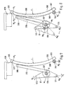
- FIG. 8 schematically shows compensation compensation when the ambient temperature rises for the compensation bimetal rod 300 according to FIG. 7.
- the dashed version of the compensation bimetal rod 300 corresponds to the arrangement in a schematic enlargement at elevated temperature compared to the solid version.
- the carrying part 310 is taken along and changes the position of the release lever 17 at its other end via the shaft axis 170 attached thereto, as shown in dashed lines.
Landscapes
- Thermally Actuated Switches (AREA)
- Breakers (AREA)
- Protection Of Generators And Motors (AREA)
Abstract
Description
- Die Erfindung befaßt sich mit einem thermischen Relais mit in einem Gehäuse untergebrachten Bimetallauslösern und einer mehrteiligen Übertragungseinrichtung, die die Bimetallausbiegung von einem Brückensystem über einen Auslösehebel und weitere Teile auf einen Hilfsschalter überträgt und die mit einem mit dem Auslösehebel zusammenwirkenden Bimetallstab zur Kompensation der Umgebungstemperatur und einer Einrichtung zum Anpassen an den Nennstrom ausgestattet ist.
- Ein solches thermisches Relais ist beispielsweise aus dem DE-GM 72 24 098 bekannt. Thermische Relais, auch als thermische Überstromrelais oder Überlastungsschutzrelais bezeichnet, dienen als zuverlässiger Motorschutz bei Überlast und Phasenausfall durch Abschaltung des Motors. Die wesentlichen Bauelemente eines solchen thermischen Schutzrelais sind Bimetallauslöser, Übertragungsmechanismus und Hilfsschalter. In der Figur 1 ist das Funktionsprinzip eines derartigen bekannten Relais dargestellt. Die vom Motorstrom I durchflossenen Bimetallauslöser 100, je Phase ein Bimetallauslöser, die vom dem Heizwendel 101 umgeben sind, wirken auf ein Brückensystem 200 mit Auslösebrücke 201 und Differentialbrücke 202. Wenn ein Bimetallauslöser bei Phasenausfall nicht so stark ausbiegt bzw. zurückläuft wie die beiden anderen, dann legen Auslösebrücke und Differentialbrücke verschiedene Wege zurück. Der Differenzweg des Brückensystems wird durch den Betätigungshebel 16 übersetzt und über den Übertragungsmechanismus mit Auslösehebel 17 und stromabhängig einstellbaren Temperaturkompensations-Bimetallstab 300 auf die Schaltwippe 400 übertragen. Die Schaltwippe fährt den Hilfsschalter 500, der als Sprungschalter mit den Öffnerkontakten 95, 96 und galvanisch hiervon getrennten Schließerkontakten 97, 98 ausgebildet ist, an und bringt diesen bei Motorüberlast zum Umschalten und schaltet das Motorschütz und damit den gefährdeten Motor ab. Mit dem Abschalten des Motors wird auch die Energiezufuhr für die mit ihm elektrisch in Reihe liegenden Bimetallauslöser 100 unterbrochen, diese kühlen sich wieder ab und gehen in die Ausgangsstellung zurück. Das Relais weist eine Stromeinstellungseinrichtung 620 auf, mit der es auf unterschiedlichen Motornennstrom einstellbar ist. Die Wiedereinschaltung des Relais kann entweder automatisch A oder von Hand H erfolgen, diese Bedienungsweise ist mittels der Wiedereinschaltsperre, die zugleich die Entsperrungstaste bildet und als Reset-Taste 600 bezeichnet wird, einstellbar. Des weiteren ist eine Aus-Test-Taste 650 vorgesehen. Durch Niederücken der Taste 650 wird der Öffner geöffnet und der Stromkreis des Motorschützes unterbrochen, ohne daß über den Schließerkontakt des Hilfsschalters eine Störmeldung erfolgt. Ein Ziehen an der gleichen Taste bewirkt die Simulation einer Auslösung, den Test. In der Testfunktion wird der Öffner geöffnet und der Schließer geschlossen. Beim Betrieb mit Wiedereinschaltsperre bleibt die Umschaltung erhalten, bis die Entsperrung durch die Entsperrungstaste erfolgt.
- Die Bimetallauslöser sprechen nicht nur auf die durch die Stromstärke erzeugte Temperatur an, sondern auch die Umgebungstemperatur beeinflußt sie. Üblicherweise werden die Relais auf eine Umgebungstemperatur von 20°C geeicht. Weicht die Umgebungstemperatur von der Eichtemperatur 20°C ab, so ändert sich die Auslösekennlinie des Relais. Im allgemeinen ist diese Schwankung des Auslösestromes unerwünscht, deshalb wird in das Relais eine Temperaturkompensation in Gestalt eines Bimetallstabes oder Bimetallstreifens eingebaut. Die Bimetallausbiegung und damit der Weg der Auslösebrücke, siehe Figur 1, ist im Beharrungszustand etwa proportional dem Quadrat des Ansprechstromes. Damit ergibt sich bei einer Eichtemperatur von 20°C ein fester Auslöseweg, der ein Maß für den Strom ist. Wird nun die Umgebungstemperatur höher oder niedriger als die Eichtemperatur, dann wird auch der Auslöseweg kleiner bzw. größer. Das heißt aber, daß der vom Relais zugelassene Ansprechstrom kleiner bzw. größer wird. Höhere Umgebungstemperaturen würden also Frühauslösung und niedrigere Temperaturen Spätauslösung verursachen. Um diese Schwankungen des Auslöseweges, die auf Veränderungen der Umgebungstemperatur beruhen, zu verhindern, ist ein Bimetallstab in dem Übertragungsmechanismus vorgesehen. Dieser sogenannte Kompensations-Bimetallstab reagiert ebenso wie die Bimetallauslöser auf die sich verändernde Umgebungstemperatur und gleicht deren Einfluß aus, so daß der Auslöseweg und damit auch der Ansprechstrom des Relais bei schwankender Umgebungstemperatur weitgehend konstant bleiben.
- Da die Bimetallauslöser auf die Stromstärke ansprechen, ist es erforderlich, das Relais, die Bimetallauslöser und auch den Kompensations-Bimetallstab auf unterschiedliche Nennströme einstellen zu können, wozu die schematisch in Figur 1 dargestellte Einrichtung 620 mit einem Exzenter vorgesehen ist, durch dessen Drehung der Anlageort und damit die Lage des Bimetallstabes und seines Auslöseweges verändert wird.
- Aus der DE-OS 37 35 161 und 37 35 135 ist bereits ein temperaturkompensierender Bimetallstreifen bekannt, der in einem Hebeltragteil drehbar aufgehängt ist und mit der Auslösebrücke der Bimetallauslöser in Kontakt steht.
- Der Erfindung liegt die Aufgabe zugrunde, die bekannten Kompensations-Bimetallelemente bezüglich ihrer Kompensationswege zu optimieren, d.h. die Genauigkeit der Auslöseströme für das thermische Relais und den Überlastschutz zu erhöhen. Gleichzeitig soll ein möglichst einfacher Weg gefunden werden, um das Kompensations-Bimetall auch an den Ansprechstrom, d.h. den Nennstrom, mit dem das thermische Relais gefahren wird, einzustellen.
- Zur Lösung dieser Aufgabe ist gemäß der Erfindung der Kompensations-Bimetallstab auf seiner ganzen Länge gleichmäßig in Form eines Kreisbogens mechanisch vorgeformt und im Bereich seines einen Endes in einem ortsfesten Drehlager geführt und im Bereich seines anderen Endes an seiner konvexen Seite an einem Exzenter einer Stromeinstellungseinrichtung abgestützt, so daß das eine Ende eines als Stab ausgebildeten Tragteiles im Bereich des abgestützten Endes des Kompensationsbimetallstabes an dessen konvexen Seite tangential anliegt, und das andere Ende des Tragteiles mit einer Wellenachse, um die der Auslösehebel drehbar ist, fest verbunden ist. Der erfindungsgemäße Kompensations-Bimetallstab ist damit in einer Doppelaufhängung gelagert und gewölbt, wodurch die Rückbiegung unter Krafteinwirkung, die aus der Bewegung des Hilfsschalters resultiert, vermindert und der Kompensationsweg vergleichmäßigt wird.
- Ein erfindungswesentliches Element ist in der selbsttragenden und spannungsfrei hergestellten gleichmäßig gekrümmten Gestalt des Bimetallstabes zu sehen. Ausgangsgestalt des Bimetallstabes ist also nicht die üblicherweise gerade Stab- und Streifenform, sondern ein definiert vorgebogener und bleibend verformter Stab. Durch die mechanisch hergestellte dauerhafte Vorkrümmung des Bimetallstabes gemäß der Erfindung wird es möglich, durch tangentiale Anschlußteile relativ große Hebelwege im Verhältnis zu einem relativ kurzen Bimetallstab für die Kompensation zu erzielen und damit die Auslösegenauigkeit zu verbessern.
- In weiterer Ausgestaltung des Kompensations-Bimetallstabes ist vorgesehen, daß dieser mit der Wellenachse, um die der Auslösehebel drehbar ist, mittels eines Tragteiles unlösbar fest, beispielsweise über Schweißbereiche, verbunden ist. Das Tragteil ist nicht aus Bimetall. Durch die kreisförmige Krümmung des Kompensations-Bimetallstabes ist es möglich, daß das Tragteil sowohl an der konvexen Seite des Kompensations-Bimetallstabes als auch an der Wellenachse für den Auslösehebel jeweils tangential anliegt und befestigt, insbesondere angeschweißt ist. Insbesondere ist vorgesehen, daß das Tragteil tangential mit seiner von dem Kompensation-Bimetallstab abgewandten Seite an der Wellenachse anliegt. Die Wellenachse, die den Auslösehebel trägt, ist nur mit dem Tragteil verbunden und macht daher die Bewegungen des Tragteiles mit.
- Durch die erfindungsgemäße Konstruktion des Kompensations-Bimetallstabes bildet dieser mit der Wellenachse des Auslösehebels über das Tragteil ein um den von dem ortsfest drehbar gelagerten Ende des Kompensations-Bimetallstabes gebildeten Drehpunkt als erstem Eckpunkt bewegbares Dreieck, dessen einer Eckpunkt durch die variable Länge des Kompensations-Bimetallstabes entsprechend dessen temperaturabhängiger Verlängerung bzw. Verkürzung bzw. durch Veränderung der Abstützung des Endes des Kompensations-Bimetallstabes verschiebbar und dessen dritter von dem Mittelpunkt der Wellenachse des Auslösehebels gebildete Eckpunkt zwangsweise durch die Veränderung der Lage des Kompensations-Bimetallstabes um eine Strecke K verstellbar wird, wordurch die Kompensation des Auslöseweges erreicht wird.
- Gemäß einem weiteren Merkmal der Erfindung ist das an dem Exzenter sich einseitig gleitend abstützende Ende des Kompensations-Bimetallstabes entsprechend der temperaturabhängigen Veränderung der Länge des Kompensations-Bimetallstabes in seiner Lage veränderbar. In einer bevorzugten Ausführung ist das in einem ortsfesten Drehlager geführte Ende des Kompensations-Bimetallstabes mit einem Achsbolzen fest verbunden und der Achsbolzen in dem Drehlager um seine sich quer zur Längserstreckung des Kompensations-Bimetallstabes entsprechende Achse drehbar. Damit erfüllt der Kompensations-Bimetallstab sowohl die Aufgaben als Steuereinheit als auch der Kompensation der Umgebungstemperatur. Der ortsfeste Drehpunkt des einen Endes des Kompensations-Bimetallstabes legt den Drehpunkt für den Auslösehebel zur Übertragung der Bimetallauslösung auf den Hilfsschalter fest, während durch den Anlagepunkt am Exzenter der Stromverstelleinrichtung das Einstellen auf den Ansprechstrom bzw. Nennstrom des Relais möglich ist. Durch Verstellen des Exzenters wird die Anlage des Bimetallstabes verändert.
- Ein Ausführungsbeispiel der Erfindung ist in der Zeichnung in der Funktion bei einem thermischen Relais sowie mit weiteren Details und Funktionschemata dargestellt.
- Es zeigen
- Figur 1 das Funktionsprinzip eines bekannten thermischen Relais für Motorschutz
- Figur 2 ein erfindungsgemäßes Motorschutzrelais in Aufsicht
- Figur 3 das Relais nach Fig. 2 in Vorderansicht
- Figur 4 einen Querschnitt durch das Relais gemäß Figur 2 und 3 durch den Motorstromanschluß
- Figur 5 einen Querschnitt durch das Relais gemäß Figur 2 im Bereich der Hilfsschalteranschlüsse
- Figur 6 einen Teilquerschnitt durch das Relais gemäß Figur 2 und 3 parallel zur Vorderansicht der Figur 3
- Figur 7 die Steuereinheit mit Temperaturkompensation in Seitenansicht
- Figur 8 die Steuereinheit gemäß Fig. 7 schematisch in Funktion
- Figur 9 schematische Darstellung der Doppelaufhängung des Kompensations-Bimetallstabes
- Das in den Figuren 2 bis 6 dargestellte Motorschutzrelais 1 arbeitet nach dem physikalischen Prinzip als Bimetallrelais, wie es anhand des Funktionsprinzips der Figur 1 erläutert wurde. In dem Gehäuse 10, das seitlich mit dem Deckel 13 und oberseitig in Teilbereichen mittels der Trägerplatte 60 abgedeckt ist, sind die Bimetallauslöser 100, siehe Figur 6, mit dem Brückensystem 200 untergebracht. Die Heizwendel 101 umgibt die einzelnen den drei Phasen entsprechenden Bimetallauslöser und ist an einem Ende über die in dem Halterahmen 67 angeordneten Steckanschlüsse 66 an eine Stromversorgungseinrichtung anschließbar. Die Anschlüsse 2, 4, 6 dienen dem Anschluß der drei Phasen des Motorstromes, der überwacht werden soll. Die Bimetallauslöser 100 sind über die Kontaktfahnen 20 hieran angeschlossen. Bei Überlast wird durch Ausbiegung der Bimetallauslöser 100 das Brückensystem 200 in Pfeilrichtung G bewegt und löst über den Betätigungshebel 16 und Auslösehebel 17 mit Bimetallkompensationsstab 300 die Schaltbewegung der Schaltwippe 400 in Pfeilrichtung F aus. Die Bewegung wird über eine Zugfeder 125, an der der Auslösehebel 17 angreift, die an einem Ende in der Schaltwippe 400 und am anderen Ende an einer am Gehäuse angeordneten Schraube 126 eingehängt ist, ausgelöst. Bei Überschreiten des in Abhängigkeit von dem Strom einstellbaren Auslöseweges werden die Kontakte 95, 96 des Hilfsschalters durch Schalten der Schaltwippe geöffnet und das nachgeordnete, hier nicht dargestellte Motorschütz schaltet den gefährdeten Motor ab. Das Relais gemäß den Figuren 2 bis 6 ist des weiteren mit der Einrichtung 620 zum Einstellen des Relais auf den Nennstrom, den es zu überwachen gilt, ausgerüstet. Darüber hinaus ist das Relais mit einem Einstellhebel, auch als Reset-Taste 600 bezeichnet, ausgerüstet, die entweder auf die Stellung "Auto" oder auf die Stellung "Hand" einrastbar ist. Bei der Einstellung "Auto", die ohne Wiedereinschaltsperre arbeitet, schaltet das Relais den Motor nach Auslösung wieder selbsttätig ein, während bei der Stellung "Hand" mit Wiedereinschaltsperre gearbeitet wird und nach der Auslösung das Relais den Motor nicht mehr einschaltet. Das Relais ist auch mit dem Testhebel 650 ausgerüstet, um von Hand eine Auslösung zum Prüfen oder zur Inbetriebnahme zu simulieren. Diese drei Funktionsteile, der Stromeinstellung, der Wiedereinschaltsperre sowie der Handauslösung für Prüfzwecke mit Testhebel sind an der Trägerplatte 60 befestigt und werden mit dieser zusammen in dem Gehäuse 10 montiert.
- Darüber hinaus ist das Relais mit dem Kompensations-Bimetallstab 300 ausgerüstet, der die Aufgabe der Kompensation der Schwankungen des Auslöseweges infolge der Veränderungen der Umgebungstemperatur hat und gleichzeitig auch noch auf unterschiedliche Nennströme einstellbar ist.
- In der Figur 7 ist der Aufbau der Steuer- und Kompensationeinheit mit dem Kompensations-Bimetallstab 300 in teilweise schematischer und vergrößerter Ansicht dargestellt.
- Der Kompensations-Bimetallstab 300 ist gleichmäßig kreisbogenförmig mit dem Radius r gekrümmt ausgebildet. In dieser Gestalt wird er eingebaut. Im Bereich des einen Endes ist der Kompensations-Bimetallstab 300 an einem festen Drehpunkt M3 gelagert. Der feste Drehpunkt bzw. Drehachse M3 wird beispielsweise durch einen Achsbolzen 302 gebildet, der in der am nicht näher dargestellten Gehäuse befestigten Lagerbuchse 304 drehbar ist. Der Kompensations-Bimetallstab 300 ist im Bereich seines Endes 301 mit dem Achsbolzen 302 fest verbunden, beispielsweise verschweißt. Der Kompensations-Bimetallstab 300 kann um die Achse des Achsbolzens 302 als festen Drehpunkt M3 in der Lagerbuchse 304 gedreht werden. Die Befestigungsstelle 301 ist bevorzugt auf der konvexen Seite 308 des Kompensations-Bimetallstabes angeordnet, sie kann jedoch auch auf der anderen Seite, d.h. der konkaven Seite vorgesehen sein.
- An dem anderen Ende 305 ist der Kompensations-Bimetallstab 300 an seiner konvexen Seite an dem Exzenter 620 der Stromverstelleinrichtung abgestützt. Die Anlagefläche 621 an dem Exzenter 620 bildet praktisch eine Art frei verschiebbares Lager für den Kompensations-Bimetallstab, wobei dieser sich gleichzeitig bei temperaturabhängiger Verlängerung oder Verkürzung an dieser Anlagefläche 621 als einseitiger Abstütz- oder Gleitfläche in seiner Längserstreckung entlangschiebt, wodurch der Anlagepunkt M2 des Kompensations-Bimetallstabes verschoben wird.
- Der Auslösehebel 17 ist um die Wellenachse 170 frei drehbar gelagert und überträgt die durch die Bimetallausbiegung der Bimetallauslöser hervorgerufene Auslösebewegung durch Anschlag an seinem Ende 171 auf das andere Ende 172. Mit diesem Ende liegt der Auslösehebel 17 an der Zugfeder 125 an, so daß er bei Bewegung über den Kippunkt hinaus die Schaltwippe 400 bewegt. Die Auslösewege, siehe Pfeile H1, H2, sind durch die Temperaturkompensation mit Hilfe des Kompensations-Bimetallstabes 300 zu eichen. Die Wellenachse 170, die den Auslösehebel 17 trägt, ist mit dem Kompensations-Bimetallstab 300 über das Tragteil 310, beispielsweise einen Metallstab starr verbunden, beispielsweise durch Verschweißen der Wellenachse 170 im Bereich 307 mit dem Tragteil 310 und im Bereich 306 durch Verschweißen des Tragteiles 310 mit dem Kompensations-Bimetallstab 300. Hierbei ist wesentlich, daß das Tragteil 310 an der konvexen Seite 308 des Kompensations-Bimetallstabes tangential angelenkt und verschweißt ist, ebenso tangential an der Wellenachse 170 des Auslösehebels. Der Mittelpunkt M1 der Wellenachse 170 ist bei Veränderung der Lage des Tragteiles 310 in Pfeilrichtung K verschiebbar und damit verlagern sich auch die Anschlagflächen bzw. verändern sich die Auslösewege der Hebel enden 171 bzw. 172, beispielsweise orientiert am Mittelpunkt M0 des Hebelendes 171 des Auslösehebels 17.
- Wie in der Figur 9 dargestellt, ist das eine Ende des Kompensations-Bimetallstabes 300 um den ortsfesten Drehpunkt M3 drehbar, während die Wellenachse 170 mit dem Mittelpunkt M1, die über das Tragteil 310 angelenkt sind in Pfeilrichtung K frei beweglich sind. Das andere Ende 305 des Kompensations-Bimetallstabes ist am Exzenter 620 längsverschiebbar geführt. Diese Verschiebbarkeit des Anlagepunktes M2 des Bimetallstabes 300 ermöglicht zum einen die Steuerung entsprechend dem einstellbaren Nennstrom, indem durch Veränderung der Lage des Exzenters 620 die Lage des Bimetallstabes verändert wird. Eine weitere Verschiebungsmöglichkeit in Pfeilrichtung K1, in Längserstreckung des Bimetallstabes, ergibt sich dadurch, daß durch Veränderung der Umgebungstemperatur bei fest eingestelltem Exzenter und damit vorgegebenen Abstützung und Anlagefläche 621 der Kompensations-Bimetallstab seine Länge verändert und damit der Anlagepunkt M2 nach M2′ verschoben wird. Damit erfüllt die Anordnung des gleichmäßig gekrümmten Kompensations-Bimetallstabes gemäß Figur 7 und 9 sowohl die Aufgabe als Steuereinheit als auch als Kompensationseinheit.
- Der Kompensations-Bimetall 300 ist in Doppelaufhängung gelagert, wobei um den festen Drehpunkt M3 der Auslösehebel von M1 nach M1′ um den Weg K verschiebbar ist entsprechend der Verschiebung des anderen Endes des Kompensations-Bimetallstabes 300 von M2 nach M2′ um den Weg K1. Diese Verschiebung kann entweder gesteuert oder aber durch Veränderung der Umgebungstemperatur ausgelöst werden.
- In der Figur 8 ist schematisch ein Kompensationsausgleich bei Erhöhung der Umgebungstemperatur für den Kompensations-Bimetallstab 300 gemäß Figur 7 dargestellt. Die gestrichelte Ausführung des Kompensations-Bimetallstabes 300 entspricht in schematischer Vergrößerung der Anordnung bei erhöhter Temperatur gegenüber der durchgezogenen Ausführung. Infolge der sich vergrößernden Krümmung des Bimetallstabes 300 bei Temperaturerhöhung verschiebt dieser sich entlang der Anlagefläche 621 des Exzenters 620 in seiner Längserstreckung in Pfeilrichtung K1. Dabei wird das Tragteil 310 mitgenommen und verändert an seinem anderen Ende über die daran befestigte Wellenachse 170 die Lage des Auslösehebels 17, wie gestrichelt dargestellt. Dadurch wird auch die Position M0 des Anschlaghebelendes 171 nach M0′ verschoben, wodurch der Auslöseweg korrigiert, d.h. entsprechend der Umgebungstemperatur kompensiert ist. Bei nur geringer Veränderung der Lage und Form des Bimetallstabes 300 infolge Temperaturänderungen werden jedoch über das tangential angelenkte Tragteil 310 relativ große Hebelwegsveränderungen von M0 nach M0′ bewirkt, wodurch eine sehr genaue Kompensation möglich ist.
Claims (6)
dadurch gekennzeichnet, daß das Tragteil (310) über Schweißbereiche (306,307) sowohl mit der konvexen Seite (308) des Kompensations-Bimetallstabes (300) als auch mit der Wellenachse (170) fest verbunden ist.
dadurch gekennzeichnet, daß der Kompensations-Bimetallstab (300) mit der Wellenachse (170) des Auslösehebels (17) über das Tragteil (310) ein um den von dem ortsfest drehbar gelagerten Ende des Kompensations-Bimetallstabes gebildeten Drehpunkt (M3) bewegbares Dreieck mit den Eckpunkten (M3, M2, M1) bildet, dessen Eckpunkt (M2) durch die variable Länge des Kompensations-Bimetallstabes (300) entsprechend der temperaturabhängigen Verlängerung bzw. Verkürzung des Kompensations-Bimetallstabes (300) bzw. durch Veränderung der Abstützung des Endes des Kompensations-Bimetallstabes (300) verschiebbar und dessen von dem Mittelpunkt (M1) der Wellenachse (170) des Auslösehebels (17) gebildeter Eckpunkt (M1) zwangsweise durch die Veränderung der Lage des Kompensations-Bimetallstabes (300) um eine Strecke (K) verstellbar ist.
dadurch gekennzeichnet, daß das an dem Exzenter (620) sich einseitig gleitend abstützende Ende (305) des Kompensations-Bimetallstabes (300) entsprechend der temperaturabhängigen Veränderung der Länge des Kompensations-Bimetallstabes in seiner Lage veränderbar ist.
dadurch gekennzeichnet, daß das Tragteil (310) tangential mit seiner von dem Kompensations-Bimetallstab (300) abgewandten Seite an der Wellenachse (170) anliegt.
dadurch gekennzeichnet, daß das in einem ortsfesten Drehlager (304) geführte Ende (301) des Kompensations-Bimetallstabes (300) mit einem Achsbolzen (302) fest verbunden ist, und der Achsbolzen in dem Drehlager (304) um seine sich quer zur Längserstreckung des Kompensations-Bimetallstabes entsprechende Achse (M3) drehbar ist.
Applications Claiming Priority (4)
| Application Number | Priority Date | Filing Date | Title |
|---|---|---|---|
| DE3840062 | 1988-11-28 | ||
| DE19883840062 DE3840062C1 (en) | 1988-11-28 | 1988-11-28 | Thermal relay having bimetallic compensation |
| DE8814783U | 1988-11-28 | ||
| DE8814783U DE8814783U1 (de) | 1988-11-28 | 1988-11-28 | Thermisches Relais mit Bimetallkompensation |
Publications (3)
| Publication Number | Publication Date |
|---|---|
| EP0371415A2 true EP0371415A2 (de) | 1990-06-06 |
| EP0371415A3 EP0371415A3 (de) | 1991-06-05 |
| EP0371415B1 EP0371415B1 (de) | 1995-01-25 |
Family
ID=25874610
Family Applications (1)
| Application Number | Title | Priority Date | Filing Date |
|---|---|---|---|
| EP89121793A Expired - Lifetime EP0371415B1 (de) | 1988-11-28 | 1989-11-25 | Thermisches Relais mit Bimetallkompensation |
Country Status (4)
| Country | Link |
|---|---|
| EP (1) | EP0371415B1 (de) |
| AT (1) | ATE117832T1 (de) |
| DE (1) | DE58908937D1 (de) |
| ES (1) | ES2069566T3 (de) |
Cited By (2)
| Publication number | Priority date | Publication date | Assignee | Title |
|---|---|---|---|---|
| US7956301B2 (en) | 2007-04-13 | 2011-06-07 | Eaton Industries Gmbh | Tamper protection device for an electrical switching device, including a protection cap and a retainer for a security seal |
| EP2620970A1 (de) * | 2012-01-26 | 2013-07-31 | Eaton Industries GmbH | Fernantrieb mit Dehnelement |
Families Citing this family (1)
| Publication number | Priority date | Publication date | Assignee | Title |
|---|---|---|---|---|
| JP4889555B2 (ja) * | 2007-04-23 | 2012-03-07 | 三菱電機株式会社 | 回路遮断器 |
Family Cites Families (2)
| Publication number | Priority date | Publication date | Assignee | Title |
|---|---|---|---|---|
| DE1131315B (de) * | 1960-07-23 | 1962-06-14 | Starkstrom Schaltgeraetefabrik | Bimetall-UEberstromrelais |
| DE1943273B2 (de) * | 1969-08-26 | 1976-03-18 | Licentia Patent-Verwaltungs-Gmbh, 6000 Frankfurt | Bimetallausloeser fuer selbstschalter |
-
1989
- 1989-11-25 ES ES89121793T patent/ES2069566T3/es not_active Expired - Lifetime
- 1989-11-25 DE DE58908937T patent/DE58908937D1/de not_active Expired - Fee Related
- 1989-11-25 AT AT89121793T patent/ATE117832T1/de not_active IP Right Cessation
- 1989-11-25 EP EP89121793A patent/EP0371415B1/de not_active Expired - Lifetime
Cited By (3)
| Publication number | Priority date | Publication date | Assignee | Title |
|---|---|---|---|---|
| US7956301B2 (en) | 2007-04-13 | 2011-06-07 | Eaton Industries Gmbh | Tamper protection device for an electrical switching device, including a protection cap and a retainer for a security seal |
| EP2620970A1 (de) * | 2012-01-26 | 2013-07-31 | Eaton Industries GmbH | Fernantrieb mit Dehnelement |
| WO2013110547A1 (de) * | 2012-01-26 | 2013-08-01 | Eaton Electrical Ip Gmbh & Co. Kg | Fernantrieb mit dehnelement |
Also Published As
| Publication number | Publication date |
|---|---|
| EP0371415B1 (de) | 1995-01-25 |
| EP0371415A3 (de) | 1991-06-05 |
| DE58908937D1 (de) | 1995-03-09 |
| ATE117832T1 (de) | 1995-02-15 |
| ES2069566T3 (es) | 1995-05-16 |
Similar Documents
| Publication | Publication Date | Title |
|---|---|---|
| DE2403839C2 (de) | Stromkreisunterbrecher mit ein freigebbares Element verriegelnder Verriegelungsvorrichtung | |
| DE2414723A1 (de) | Ueberstrom-schutzschalter | |
| EP0371415B1 (de) | Thermisches Relais mit Bimetallkompensation | |
| DE741351C (de) | UEberstromschalter | |
| DE3840062C1 (en) | Thermal relay having bimetallic compensation | |
| DE69733168T2 (de) | Betätigungsmechanismus für elektrischen Schutzschalter mit grossen Öffnungswinkel | |
| DE2445693C3 (de) | Überstromschalter | |
| DE1115352B (de) | Thermischer UEberstromschalter mit von Hand betaetigbarem Schaltschieber | |
| DE3840064A1 (de) | Thermisches relais mit schaltwippe | |
| DE3602123A1 (de) | Sicherungsautomat mit einem elektromagnet zur fernsteuerung eines wegrueckbaren unterbrecherkontakts und einem organ zur uebertragung der bewegung des ankers des elektromagnets auf einen bezueglich der bewegung des ankers versetzten punkt dieses kontakts | |
| DE3106004C2 (de) | Leistungsschalter | |
| DE2706742A1 (de) | Mehrpoliger ueberstromschutzschalter | |
| EP0556602B1 (de) | Thermischer Auslöser für elektrische Schaltgeräte | |
| DE8814783U1 (de) | Thermisches Relais mit Bimetallkompensation | |
| DE1161974B (de) | Durch einen Bimetallarm betaetigter Schnappschalter | |
| DE2625817C3 (de) | Selbstschalter | |
| EP2345056B1 (de) | Elektrisches überlastrelais mit einer schwenkbar gelagerten wippe | |
| DE1181304B (de) | Elektromagnetischer Ausloeser fuer einen Selbstschalter | |
| DE3840063C2 (de) | ||
| DE1197539B (de) | Elektrischer Kipphebelselbstschalter | |
| DE1083413B (de) | Thermischer UEberstromausloeser | |
| AT163973B (de) | Schütz mit thermischer Auslösung | |
| DE3413454C2 (de) | ||
| DE739894C (de) | Bimetallausloesevorrichtung fuer elektrische Schalter | |
| DE593008C (de) | Selbsttaetiger Bimetalltemperaturregler, insbesondere fuer elektrisch beheizte Geraete |
Legal Events
| Date | Code | Title | Description |
|---|---|---|---|
| PUAI | Public reference made under article 153(3) epc to a published international application that has entered the european phase |
Free format text: ORIGINAL CODE: 0009012 |
|
| AK | Designated contracting states |
Kind code of ref document: A2 Designated state(s): AT BE CH DE ES FR GB IT LI NL |
|
| PUAL | Search report despatched |
Free format text: ORIGINAL CODE: 0009013 |
|
| AK | Designated contracting states |
Kind code of ref document: A3 Designated state(s): AT BE CH DE ES FR GB IT LI NL |
|
| RAP1 | Party data changed (applicant data changed or rights of an application transferred) |
Owner name: KLOECKNER-MOELLER GMBH |
|
| 17P | Request for examination filed |
Effective date: 19911018 |
|
| 17Q | First examination report despatched |
Effective date: 19940217 |
|
| GRAA | (expected) grant |
Free format text: ORIGINAL CODE: 0009210 |
|
| AK | Designated contracting states |
Kind code of ref document: B1 Designated state(s): AT BE CH DE ES FR GB IT LI NL |
|
| PG25 | Lapsed in a contracting state [announced via postgrant information from national office to epo] |
Ref country code: NL Effective date: 19950125 Ref country code: BE Effective date: 19950125 |
|
| REF | Corresponds to: |
Ref document number: 117832 Country of ref document: AT Date of ref document: 19950215 Kind code of ref document: T |
|
| ET | Fr: translation filed | ||
| ITF | It: translation for a ep patent filed | ||
| REF | Corresponds to: |
Ref document number: 58908937 Country of ref document: DE Date of ref document: 19950309 |
|
| REG | Reference to a national code |
Ref country code: ES Ref legal event code: FG2A Ref document number: 2069566 Country of ref document: ES Kind code of ref document: T3 |
|
| GBT | Gb: translation of ep patent filed (gb section 77(6)(a)/1977) |
Effective date: 19950420 |
|
| NLV1 | Nl: lapsed or annulled due to failure to fulfill the requirements of art. 29p and 29m of the patents act | ||
| PLBE | No opposition filed within time limit |
Free format text: ORIGINAL CODE: 0009261 |
|
| STAA | Information on the status of an ep patent application or granted ep patent |
Free format text: STATUS: NO OPPOSITION FILED WITHIN TIME LIMIT |
|
| PG25 | Lapsed in a contracting state [announced via postgrant information from national office to epo] |
Ref country code: LI Effective date: 19951130 Ref country code: CH Effective date: 19951130 |
|
| 26N | No opposition filed | ||
| REG | Reference to a national code |
Ref country code: CH Ref legal event code: PL |
|
| PGFP | Annual fee paid to national office [announced via postgrant information from national office to epo] |
Ref country code: GB Payment date: 20001109 Year of fee payment: 12 |
|
| PGFP | Annual fee paid to national office [announced via postgrant information from national office to epo] |
Ref country code: AT Payment date: 20001122 Year of fee payment: 12 |
|
| PGFP | Annual fee paid to national office [announced via postgrant information from national office to epo] |
Ref country code: ES Payment date: 20011119 Year of fee payment: 13 |
|
| PG25 | Lapsed in a contracting state [announced via postgrant information from national office to epo] |
Ref country code: GB Free format text: LAPSE BECAUSE OF NON-PAYMENT OF DUE FEES Effective date: 20011125 Ref country code: AT Free format text: LAPSE BECAUSE OF NON-PAYMENT OF DUE FEES Effective date: 20011125 |
|
| REG | Reference to a national code |
Ref country code: GB Ref legal event code: IF02 |
|
| GBPC | Gb: european patent ceased through non-payment of renewal fee |
Effective date: 20011125 |
|
| PGFP | Annual fee paid to national office [announced via postgrant information from national office to epo] |
Ref country code: DE Payment date: 20021024 Year of fee payment: 14 |
|
| PG25 | Lapsed in a contracting state [announced via postgrant information from national office to epo] |
Ref country code: ES Free format text: LAPSE BECAUSE OF NON-PAYMENT OF DUE FEES Effective date: 20021126 |
|
| PGFP | Annual fee paid to national office [announced via postgrant information from national office to epo] |
Ref country code: FR Payment date: 20031107 Year of fee payment: 15 |
|
| REG | Reference to a national code |
Ref country code: ES Ref legal event code: FD2A Effective date: 20031213 |
|
| PG25 | Lapsed in a contracting state [announced via postgrant information from national office to epo] |
Ref country code: DE Free format text: LAPSE BECAUSE OF NON-PAYMENT OF DUE FEES Effective date: 20040602 |
|
| PG25 | Lapsed in a contracting state [announced via postgrant information from national office to epo] |
Ref country code: FR Free format text: LAPSE BECAUSE OF NON-PAYMENT OF DUE FEES Effective date: 20050729 |
|
| REG | Reference to a national code |
Ref country code: FR Ref legal event code: ST |
|
| PG25 | Lapsed in a contracting state [announced via postgrant information from national office to epo] |
Ref country code: IT Free format text: LAPSE BECAUSE OF NON-PAYMENT OF DUE FEES;WARNING: LAPSES OF ITALIAN PATENTS WITH EFFECTIVE DATE BEFORE 2007 MAY HAVE OCCURRED AT ANY TIME BEFORE 2007. THE CORRECT EFFECTIVE DATE MAY BE DIFFERENT FROM THE ONE RECORDED. Effective date: 20051125 |