EP0371573A2 - Vorrichtung für die Kapillar-Elektrophorese - Google Patents
Vorrichtung für die Kapillar-Elektrophorese Download PDFInfo
- Publication number
- EP0371573A2 EP0371573A2 EP89250095A EP89250095A EP0371573A2 EP 0371573 A2 EP0371573 A2 EP 0371573A2 EP 89250095 A EP89250095 A EP 89250095A EP 89250095 A EP89250095 A EP 89250095A EP 0371573 A2 EP0371573 A2 EP 0371573A2
- Authority
- EP
- European Patent Office
- Prior art keywords
- capillary tube
- sample
- light
- slits
- medium
- Prior art date
- Legal status (The legal status is an assumption and is not a legal conclusion. Google has not performed a legal analysis and makes no representation as to the accuracy of the status listed.)
- Granted
Links
Images


Classifications
-
- G—PHYSICS
- G01—MEASURING; TESTING
- G01N—INVESTIGATING OR ANALYSING MATERIALS BY DETERMINING THEIR CHEMICAL OR PHYSICAL PROPERTIES
- G01N27/00—Investigating or analysing materials by the use of electric, electrochemical, or magnetic means
- G01N27/26—Investigating or analysing materials by the use of electric, electrochemical, or magnetic means by investigating electrochemical variables; by using electrolysis or electrophoresis
- G01N27/416—Systems
- G01N27/447—Systems using electrophoresis
- G01N27/44756—Apparatus specially adapted therefor
- G01N27/44782—Apparatus specially adapted therefor of a plurality of samples
-
- G—PHYSICS
- G01—MEASURING; TESTING
- G01N—INVESTIGATING OR ANALYSING MATERIALS BY DETERMINING THEIR CHEMICAL OR PHYSICAL PROPERTIES
- G01N27/00—Investigating or analysing materials by the use of electric, electrochemical, or magnetic means
- G01N27/26—Investigating or analysing materials by the use of electric, electrochemical, or magnetic means by investigating electrochemical variables; by using electrolysis or electrophoresis
- G01N27/416—Systems
- G01N27/447—Systems using electrophoresis
- G01N27/44704—Details; Accessories
- G01N27/44717—Arrangements for investigating the separated zones, e.g. localising zones
- G01N27/44721—Arrangements for investigating the separated zones, e.g. localising zones by optical means
-
- G—PHYSICS
- G01—MEASURING; TESTING
- G01N—INVESTIGATING OR ANALYSING MATERIALS BY DETERMINING THEIR CHEMICAL OR PHYSICAL PROPERTIES
- G01N27/00—Investigating or analysing materials by the use of electric, electrochemical, or magnetic means
- G01N27/26—Investigating or analysing materials by the use of electric, electrochemical, or magnetic means by investigating electrochemical variables; by using electrolysis or electrophoresis
- G01N27/416—Systems
- G01N27/447—Systems using electrophoresis
- G01N27/44704—Details; Accessories
- G01N27/44743—Introducing samples
Definitions
- This invention relates to techniques in the separation sciences and more particularly to techniques for: (1) injecting samples into a separating apparatus; (2) separating molecular species of the samples with low band spreading; and (3) monitoring the separated molecular species of the samples.
- One class of electrophoresis apparatus is a capillary electrophoresis apparatus.
- the medium is in a capillary tube. This tube is usually made of fused quartz.
- the electrophoresis medium may be a gel or liquid in capillary electrophoresis.
- a detector transmits light through the medium phase and senses the species as they move along the medium by differences in absorbance of the light.
- the sensing of molecular species is accomplished by transmitting light from a light source section through the medium and into a light detecting section.
- the light detector is positioned in the light detection section where it receives light and converts the light to an electrical signal representing the transmittance of light through a band.
- Another aspect of the prior art capillary electrophoresis apparatus is that, under some circumstances, a relatively high potential is used to increase the speed of migration of the molecular species through the electrophoresis medium. This is intended to increase the sharpness of the peaks and provide better resolution.
- the electrophoresis medium in prior capillary electrophoresis apparatus (inside diameter of capillary tube less than 0.01 inch) has a vertical orientation at least at some locations.
- the convection currents in the medium have a component of motion in the direction of migration of the molecular species in a vertical portion of the medium, the velocities of movement of the molecular species in different portions of a band are changed with respect to each other. This causes band spreading and a reduction of resolution.
- the disadvantages caused by the convection currents may be minimized by using a small internal diameter capillary tube to hold the medium because: (1) more heat per unit of length is generated in a larger capillary tube; and (2) there is a longer thermal path to the inside wall of a larger capillary tube than a smaller capillary tube and more space for convection cells to form.
- small capillaries result in small peak volumes making detection less sensitive.
- One type of sample injector injects very small samples by applying a vacuum on the end of the separating apparatus opposite to the source of the sample to draw a small portion of the sample into the separating apparatus.
- the prior art sample injectors of this type control the amount of sample by timing the period through which the vacuum is applied. The time is determined by experience.
- This type of prior art sample injector has a disadvantage of not being as precise as desired.
- apparatus for detecting bands having a predeterminded direction of motion in a separation medium comprises a light source; a light detector; and means for positioning said light source and light detector on opposite sides of said separating medium.
- the apparatus is characterized in that the light source includes a first slit through which light passes and the detector includes a second slit for receiving light after it has passed through said medium.
- the first and second slits are aligned with the predetermined direction of motion of said bands.
- the maximum width of said first and second slits is no greater than three times nor less than one-half the inner diameter of said separation medium and the maximum length of said slit is no greater than one hundred times the diameter of said separating medium.
- the maximum length of each of said first and second slits is less than 500 micrometers, the maximum width is less than 200 micrometers, and the first and second slits are positioned at distances no greater than 1500 micrometers from each other.
- the apparatus includes means for adjusting the slits with respect to each other and means for detecting light passing through said second slit.
- the separation medium is within a capillary tube and the distance between the slits is between one and three times the outside diameter of the capillary tube.
- the capillary tube has a diameter no greater than 700 micrometers and is substantially horizontal for a continuous portion between an injector and detector with no vertical lengths having a dimension greater than one third of the length between the injecting means and the detecting means; said portion being to the point on said capillary tube where the sensing takes place.
- a sample injector having a vacuum source; a source of samples; and a vacuum chamber.
- the vacuum chamber communicates with one end of a separating means; said separating means having a second end which communicates with a sample source, means for creating a vacuum in said vacuum chamber to draw sample from said source of sample wherein sample is pulled at a slow rate into said second end of the separating means; and pressure measuring means adapted to measure the pressure in said vacuum chamber and generate a signal indicative thereof.
- the pressure sensor is adapted to control the transfer of sample and the pressure measuring device includes an integrator for integrating a signal representing the pressure in the vacuum chamber wherein the amount of the sample introduced into said second end of the separation means may be detected.
- the separating apparatus of this invention has several advantages, such as for example: (1) noise is reduced by the superior transmission of light from a light source through a very small sensing area into the light detector; (2) band spreading is reduced by constraining convection currents in the medium to motion in a direction orthogonal to the direction of migration of the molecular species being sensed; and (3) greater precision of sample injection is provided.
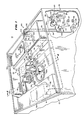
- FIG. 1 there is shown a capillary electrophoresis apparatus 10 having a cabinet 12, a power supply 14, a sample injection system 16, a sensing section 18, a sample changing system 20, and an electrophoresis section 22.
- the cabinet 12 is shown in FIG. 1 with its top removed. It supports the power supply 14, the sample changing system 20, the electrophoresis section 22, the sensing section 18 and the sample injection system 16, which are connected together to separate molecular species.
- the electrophoresis section 22 is connected to the sample changing system 20 and adapted for maintaining at least one portion of the electrophoretic separating region of the capillary tube horizontal.
- the sensing section 18 is connected to the electrophoresis section 22 and includes a novel light absorbance detection cell for monitoring the separation, and an improved way of introducing a precise sample volume to be described hereinafter.
- the sample changer section 20 causes one end of the capillary tube 30 to contact a sample and the sample injection system 16 pulls sample into the end, and causes one end of the capillary tube to be in contact to a buffer at a potential suitable for electrophoresis. Power is applied at a high potential while the sample is within the part of the capillary tube which is horizonatal to rapidly electrophoresis with low diffusion.
- the separated bands are sensed by transmitting light through narrow slits on opposite sides of the separating medium in the sensor and determining the absorbance of the bands.
- substantially horizontal as applied to the electrophoresis medium, means horizontal enough so as to not have convection currents with a substantial component of motion in the direction of migration of the molecular species and thus sufficiently horizontal to avoid band spreading from thermal convection currents at high voltages of electrophoresis.
- angle of the separating medium will be less than 15 degrees from a plane orthogonal to the force of gravity.
- a section of horizontal capillary tube of at least 100 millimeters in length is normally used to perform such high potential electrophoresis according to one embodiment of the invention.
- the sample changing section 20 inserts one end of the capillary tube into a sample, and after the sample injection system section 16 has pulled sample into the end, the sample changing system 20 inserts the end of the capillary tube into a buffer. Power is applied and, when the sample is in a horizontal portion of the capillary tube, the voltage is increased to speed the separation.
- the capillary tube is horizontal throughout its length of electrophoresis and the sample changer need not move the end of the capillary tube from the sample to the buffer.
- the horizontal capillary containing sample is inserted horizontally into the buffer by means of some suitable method such as piercing a resealable container.
- the sample containers and buffer are moved into contact with the end of the capillary tube rather than moving the end of the capillary tube.
- the electrophoresis section 22 is located within the cabinet 12 for temperature control during electrophoresis and includes a capillary tube 30, a removable horizontal cover plate 32 and a horizontal ledge 34, which cover plate 32 rests on the horizontal ledge 34 in the cabinet 12.
- the removable horizontal cover plate 32 and horizonal ledge 34 contain the capillary tube 30 between them within a recess in the horizontal ledge 34 shaped to permit a change in the length of the capillary tube 30 between the removable horizontal cover plate 32 and horizontal ledge 34. This permits the movement of the end of the capillary tube 30 by a sample changer while the capillary tube 30 is maintained in a horizontal position even though the distance between the sample changer and the light sensor changes.
- the capillary tube 30 has: (1) a first end that extends from the electrophoresis section into the sample changing system 20 where it is held for contact with the sample and buffer, which may be by movement into the sample and buffer solution; (2) a central section within the electrophoresis section which is horizontal and through which electrophoresis takes place under some circumstances at high voltage; and (3) a second end section that extends from the electrophoresis section into the sensing section 18 and sample injection system 16.
- the capillary tube 30 is made of quartz in the preferred embodiment with an inside diameter of between 0.03 and 0.2 millimeter and may include any mobile separating medium.
- the capillary tube wall in the preferred embodiment is in the thickness range of between 0.1 and 0.2 millimeters. While a capillary tube of the conventional type for electrophoresis is contemplated for the preferred embodiment, other sizes of tubes and tubes of other materials may obviously be used.
- the horizontal ledge 34 and removable horizontal cover plate 32 are preferably made of highly thermally conductive material and/or the removable horizontal cover plate 32 includes extensive perforations to facilitate cooling of the capillary tube 30.
- the removable horizontal cover plate 32 may be removed with handle 36.
- a notch 40 is provided at one side (the left end as viewed in FIG. 1) in horizontal ledge 34 to receive the capillary tube 30 from the sample changing system 20; and (2) another notch is provided in the other end, which is the right end as viewed in FIG. 1, to permit the capillary tube 30 to pass out of the electrophoresis section through hole 38 in the sensing section 18.
- the sample changing system 20 includes a sample holding reel 44, a movable arm 46, a rotor head 48 and an electrolyte section 50.
- the sample holding reel 44 and electrolyte section 50 contain sample and electrolyte in spaced apart containers and the movable arm 46 is carried by the rotor head 48 and is movable in two directions to insert an electrode in the electrolyte and the end of the capillary tube 30 into the electrolyte and sample.
- This electrode 52 and the capillary tube 30 are mounted by a bracket 54 to moveable arm 46 of the sample changing system 20.
- the bracket 54 mounts the capillary tube 30 at a horizontal level that is, when the end capillary tube is lowered into contact with the electrolyte, the same as the level of the recess in the horizontal cover plate 34 and the level of the sensor 72 so as to maximize the length that is horizontal.
- the arm moves up and down through slot 56 in rotor head 48 of the sample changing system 20.
- the arm and its shaft move up and down and rotate and the rotor casing is not necessary. This enables dipping the capillary tube 30 in sample vials indicated as 58A, 58B, (etc.) in the removable sample holding reel 44.
- the removable sample holding reel 44 is programmably rotatable to bring any of its 40 sample tubes under capillary tube 30 and rotor head 48 is rotatable to place the capillary tube 30 either over a sample tube or over electrolyte vessels 60A, 60B or 60C in the electrolyte section 50.
- movable arm 46 moves downward to put the end of capillary tube 30 either in contact with the sample in the sample tube or with the electrolyte 62A, 62B or 62C in an electrolyte vessel.
- platinum electrode 52 also dips into the vessel.
- the desired electrolyte vessel is selected both by the electrode 52 and the capillary tube 30.
- the sensing section 18 includes an absorbance monitor 70 and a sensor 72.
- the absorbance monitor 70 and sensor 72 utilize the optics, circuitry and structure of the absorbance detector described in United States patents 4,726,680 and 4,523,097 for liquid chromatography absorbance detectors.
- the absorbance monitor 70 incorporates a light source for illuminating one side of sensor 72 and a light detector for detecting light exiting the opposite side of sensor 72. It is substantially the same detector turned on its side so that the flow cell is on top and has a horizontal flow axis or plane, instead of being mounted on the side of the detector and having a vertical flow axis or plane.
- the flow cell and separating system are adapted for capillary electrophoresis as described herein, instead of for liquid chromatography as described in the foregoing patents.
- the capillary tube 30 enters sensor 72 (FIG. 1) through a tubing-holding fitting 74 (FIG. 1).
- Sensor 72 is equipped with adjustable slits to align a very narrow measuring light beam so that it goes exactly through the liquid filled part of the capillary tube 30.
- the position of the slits is adjusted by screw adjustment 76 (FIG. 1) as described hereinafter.
- the sample injection system 16 includes a controllable pressure buffer and electrode assembly 80, an electrical interface 82, a low vacuum tank 84 and a pressure control solenoid valve 88.
- the buffer and electrode assembly 80 measures the vacuum pressure in contact with the surface of the buffer during sample injection and provides an electrical connection to the capillary tube 30 during electrophoresis. For these purposes, it is electrically connected to the power supply 14 through a conductor 90, to the electrical interface 82 to provide a measured pressure signal through a cable 92 and to the pressure control solenoid valve 88 through a pressure line or connecting tubing 94.
- the pressure control solenoid valve 88 communicates with the vacuum tank 84 which is connected to the pump assembly 86.
- the electrical interface 82 may include an integrator to provide a signal proportional to the sample or integration and may be performed in a computer connected to the electrical interface 82.
- the capillary tube 30 extends into electrode buffer vessel 96 fitted with removable cap 98 as it exits the sensor 72.
- the capillary tube no longer needs to be kept horizontal after leaving the sensor 72 since the separation has already been measured optically.
- the vessel is partly filled with electrolyte buffer 100.
- the removable cap 98 is pierced by platinum electrode 102 and the capillary tube 30 and platinum electrode 102 dip into electrolyte buffer 100.
- electrical conductor 90 is connected to electrode 102 and to the ground terminal 105 of power supply 14.
- Connecting tubing 94 also pierces cap 98, but does not dip into electrolyte buffer 100.
- the connecting tubing 94 communicates with the common port 108 of pressure control solenoid valve 88.
- Normally open port 110 of this valve is vented to the atmosphere and the normally closed connection 112 of this valve is connected to tubing 114 which leads to low-vacuum tank 84 so that energization of the pressure control solenoid valve 88 applies vacuum pressure to the buffer and sample measuring assembly 80.
- a conductor 116 is electrically connected to a controller or computer or a manually-operated electrical switch 117 connected to a source of power and supplies power to the solenoid of the pressure control solenoid valve 88.
- This controller or manually-operated electrical switch supplies signals to initiate the sample injection while the capillary is held in the sample well by the movable arm 46.
- tubing 120 connects the low-pressure vacuum tank 84 to vacuum pump assembly 86.
- the vacuum pump assembly 86 includes a vacuum pump 122 mechanically connected to electric motor 124 through coupling 126.
- a vacuum sensor 128 turns on motor 124 through a signal on lead 130 when the pressure in the tank becomes too high. This establishes a controlled negative pressure in the tank 84.
- the setting of the vacuum sensor is adjustable or programmable.
- the high voltage power supply 14 is located inside the cabinet 12 and is fitted with ground terminal 105 and high voltage terminal 132.
- the power supply 14 is preferably capable of supplying a regulated voltage from 1,000 to 40,000 volts at a current of up to 100 microamperes.
- a high voltage insulated cable 134 is connected to high voltage terminal 132 and terminates in platinum wire electrode 52.
- a conventional air cooling and temperature control unit (not shown) are housed in cabinet 12.
- a fan incorporated in this unit blows temperature conditioned air out through vent slots 140 located in venting unit 136.
- Return air to the air conditioning mechanism is through vent slots 138.
- This air conditioning feature ensures that the electrophoresis process operates at a repeatable temperature that does not vary significantly over a period of time.
- the air enters and flows above the sensor 72, and then is routed past the capillary tube between its sample inlet end and the sensor 72 by conventional baffling not shown in the figure.
- Temperature control of electrophoretic separations is a common feature of electrophoresis apparatus.
- FIG. 2 there is shown a sectional view of the cabinet 12 taken through lines 2-2 of FIG. 1 and showing the rotor head 48, movable arm 46, capillary tube 30, sample vials such as 58B and a lid 144.
- the cabinet 12 is: (1) insulated; (2) includes a top surface 12A that slopes upward from front to back; and (3) is fitted with a lid 144 (FIG. 2) which preferentially has metal sides and a transparent top.
- the lid 144 is hinged to the cabinet 12 with hinge or hinges 150.
- the cabinet 12 preferentially has an outer metal surface which, along with the sides of the lid 144, are electrically grounded for safety.
- the bracket 54 mounts the capillary tube 30 at a location adjacent to the electrode 52 so that the capillary tube 30 is insertable into the sample vial 58B and the electrode 52 may be moved to the buffer compartment 62A for insertion in the buffer 60A by rotating the arm 46.
- a rotor 49 rotates the table 44 to move a new sample in position under the arm and the arm is swingable between the buffer compartment 62A and the sample housing reel 44.
- the capillary tube extends through the notch 40 in the removable horizontal ledge 32 (FIG. 1) where it is inserted into coils therein which expand or contract to take more or less tubing.
- the capillary tube 30 remains horizontal between its connection with the bracket 54, the recess in the removable horizontal ledge 32 (FIG. 1) and the sensor 72 (FIG. 1).
- FIG. 3 there is shown a simplified fragmentary view of a movable arm 46, an electrical conductor 134 for high voltage, a capillary tube 30, and a sensor 72 with the capillary tube 30 being positioned in a recess in the ledge 34 (the cover plate 32 is removed in this view).
- the bracket 54 is shown having a first opening adapted to mount one end of the capillary tube 30 and a second opening adapted to connect the electrode 52 to the conductor 134 for movement with the end of the capillary tube 30.
- the horizontal ledge 34 includes a recess in which the capillary tube 30 is coiled so that it may receive more or less tubing as the movable arm 46 swings between a buffer location and a sample location.
- the bracket 54 supporting the capillary tube 30, the recess in the surface 34 and the fitting for the sensor 72 are all in the same horizontal plane so that, as the .pa electrophoresis apparatus is operated, the capillary remains horizontal.
- FIG. 4 there is shown an axial section
- FIG. 5 there is shown an orthogonal cross section of a capillary electrophoresis tube 30 that is not horizontal.
- a capillary electrophoresis tube 30 As shown in this view, there are convection patterns in a liquid electrophoresis medium within the capillary electrophoresis tube when high voltage has caused heating of the liquid. It is a tube whose axis is either vertical or partly vertical.
- the capillary tube 30 is shown magnified in this view but with exaggeratedly thin walls.
- the inside diameter of the tube is 50 to 75 micrometers and the outside diameter is 375 micrometers.
- the length of the interior of the tube is filled with a liquid buffer electrolyte.
- An electric field is established along the axis of the tube by conventional means and electric current flows through the tube. The electric current, although small, is sufficient to cause heating of the electrolyte.
- the heat dissipation is initially constant throughout the cross section of the electrolyte, and heat is dissipated from the electrolyte, through the walls of the quartz capillary tube and to the surrounding air. Since the electrolyte is cooled along the inner tube walls, its temperature is higher in the center of the tube than at the inside diameter of the tube. This effect is regenerative, as the higher temperature at the center increases the conductivity there, causing more current to flow (and more heat to be generated) in the center.
- convection cells indicated at 140, 142 and 144 are disposed with its axis at least partly vertical. This is because the electrolyte is warmer and therefore less dense in the center of the tube and cooler and therefore more dense at the edge of the tube. These convection cells have a component of fluid motion that is parallel to the axis of the tube and therefore tend to spread narrow zones of partially separated electrophoresed sample in the axial direction. This is undesirable as it decreases the resolution of the separation.
- One method of avoiding this band spreading is to keep the electric power dissipation within the tube low enough so that these convection cells do not form. This sets an undesirable limitation on the maximum amount of electric field that can be used and therefore sets a limitation on the speed of the separation.
- a faster separation may be obtained in accordance with the novel technique described in this application using a higher electric field. This faster separation is desirable for more efficient use of time and to decrease peak broadening due to time-dependent phenomena such as diffusion.
- a larger inside diameter horizontal capillary tube can be used instead of or in addition to a higher field. The larger diameter has a significant advantage because larger cross- sectional area separated peaks result. These larger volume peaks can be detected with greater concentration sensitivity than smaller volume peaks.
- FIG. 6 there is shown an axial section
- FIG. 7 there is shown an orthogonal cross section of a the capillary tube 30 illustrating the convection patterns that result in a horizontal capillary tube operated at sufficiently high voltage and current for convection to take place.
- FIG. 8 there is shown a side view partly broken out and sectioned showing the sensor 72 having an adjustment section 160, an optical slit section 162, a first fitting assembly 164 for the capillary tube 30, and a second fitting assembly 166 for the capillary tube 30.
- the capillary tube 30 is received in the first and second fittings 164 and 166, which cause the capillary tube 30 to extend along the axis of the sensor 72 and between the slits in the optical slit section 162.
- the location of the two slits in a direction perpendicular to the axis of the capillary tube 30 is adjusted by the adjustment section 160.
- the sensor 72 is attached to a cassette or mounting plate for mounting in the absorbance monitor 70 (FIG. 1) and receives the capillary tube 30.
- the two fitting assemblies 164 and 166 are adjustable. They are identical in structure and only the fitting assembly 166 will be described in detail herein.
- the fitting assembly 166 includes a rubber washer 180, a stainless steel squeezer 182, a plastic threaded closure 184 and a plastic threaded fastener 186.
- the threaded fastener 186 is positioned to be tightened to hold the threaded closure 184 in place where it supports a threaded sleeve.
- the threaded fastener 186 also presses the stainless squeezer 182 against the rubber washer 180 so as to provide a seal around the capillary tube 30.
- the housing 188 of the sensor 72, the threaded fastener 186 and the threaded closure 184 are all formed of a relatively hard plastic such as Delrin (trademark of the DuPont Corporation).
- the washer 180 is a flexible, elastomeric material which may be the thermoplastic rubber Kraton.
- a central aperture extends through the washer 180, the stainless steel squeezer 182, the threaded closure 184 and the fastener 186 to accommodate the capillary tube 30 which extends along the longitudinal axis, past the optical slit section 162 where the optical sensing is performed and through the fitting assembly 164 on the opposite side of the sensor 72.
- the washer 180 is generally cylindrical with a cylindrical central opening receiving the capillary tube 30. It fits conformably in a counterbore within the housing 188 of the sensor.
- the stainless steel squeezer 182 is generally cylindrical but has an inwardly tapering cone positioned adjacent to the washer 180 and a central aperture to accommodate the capillary tube 30 so that when it is pressed inwardly, it forces the washer inwardly towards its central opening and outwardly against the counterbore.
- the threaded fastener 186 includes a thumb handle 190 and a threaded shank 192, with the threaded shank 192 extending downwardly through the plastic threaded closure 184 where it engages a correspondingly threaded metal sleeve 194 threaded into a tapped hole of the Delrin housing.
- the threads within the tapped hole are within a metal sleeve molded within the aperture of the Delrin housing so as to remain fixed in position and still accommodate threads.
- the mechanism of the fittings are designed to accommodate the capillary tube 30 in such a way that the capillary tube 30 is held immobile in the light sensor 72.
- the adjustment section 160 includes an adjustment screw 76 fixedly mounted (by convential means not shown in the figure) with respect to the housing 188 and an optical slit carriage 200.
- the optical slit carriage 200 is stainless steel and threaded at 202 in its upper portion with internal threads complementary to the external threads on a shank of the tightening screw 76 so that as the adjustment screw 76 is rotated, the carriage is moved up and down with respect to the housing 188 of the sensor 72.
- the optical slit section 162 is mounted to the bottom of the optical slit carriage 200 so as to be raised and lowered therewith and includes on each side a relatively short optical slit 206 having a longitudinal axis aligned with the longitudinal axis of the capillary tube 30.
- FIG. 9 shows the narrow dimension of the slits, which is 100 micrometers in the preferred embodiment.
- the distance between the slits is between one and three times the outside diameter of the capillary tube.
- the rubber washer 180 is compressed around the capillary tube 30 to hold the tube in place.
- the rubber washer 180 preferably is made of white, food grade, Kraton (trademark) thermoplastic rubber which does not deposit any ultraviolet light absorbing materials on the quartz tube as the tube is pushed through the washer. Kraton is available from Shell Corporation.
- the rubber is compressed radially to tighten around the tube by pushing the female cone-shaped stainless steel squeezer 182 against it by turning a plastic threaded fastener 186.
- the threaded fastener 186, stainless steel squeezer 182 and washer 180 are captivated within the housing 188 of the light sensor 72 by the threaded closure 184 which screws into a threaded recess in the housing 188.
- the tightener, captivator and housing are advantageously made out of Delrin (trademark of DuPont) plastic.
- the optical slit carriage 200 is moved with the adjustment screw 76 to center a pair of optical slits, one of which is shown at 206, each being 0.01 inch (250 micrometers) long by 0.004 inch (100 micrometers) wide, over the capillary tube 30 extending through the light sensor.
- the dual slits are exactly corresponding elements mounted exactly opposite each other across a bifurcation of the optical slit carriage (FIG. 9).
- the capillary tube 30 lies within the bifurcation.
- the long direction of the slit is parallel to the axis of the capillary tube 30.
- the protective polyimide protective coating of the quartz capillary tube 30 must be removed because it absorbs ultraviolet light. This is easily done by burning it off with a match or cigarette lighter in the region which is to be located between the optical slits. After burning the coating off, the capillary tubing 30 must be cleaned with very pure acetone. Any area of the capillary tubing 30 that does not have an intact polyamide coating is very fragile and must be handled with more than normal care.
- Both Delrin tighteners on the light sensor 72 are loosened, and the capillary tube 30 is gently fed through one tightener, through the rubber washer, through the optical slit region, through the other washer and tightener, and moved to the desired position with the polyamide-free region of the capillary tubing 30 between the slits. Then the two tighteners are screwed down finger tight, thus firmly captivating the capillary tubing 30 in the light sensor.
- the sensor 72 is inserted in the absorbance monitor 70 located within the cabinet 12 in FIG. 1.
- the sensor is generally shown at 72.
- the capillary tube 30 is filled with water or buffer.
- Light from the light source of the absorbance monitor enters one of the pair of slits in the sensor 72, and when the sensor 72 is properly adjusted, light exits the other slit and impinges upon the light detector of the absorbance monitor.
- the adjustment screw shown as 76 in FIGS. 1, 8 and 9
- the adjustment screw is rotated and the indication of the absorbance monitor 70 is monitored. Starting at one extreme of rotation on the tightening screw 76, and referring to FIG. 10, the following is observed.
- the slit is entirely beyond the capillary tube 30 and light travels through the free space between the pair of slits.
- the adjustment screw 76 is rotated, the light beam cuts through the curved edge of the capillary tube 30 which deflects most of the light going through the first slit so it does not go through the second slit.
- the capillary tube 30 Before operating the capillary electrophoresis apparatus, the capillary tube 30 should be arranged as shown in FIG. 1. Samples to be separated should be placed in sample tubes on sample holding reel 44. Electrolyte buffers suitable for the separation placed in electrolyte vessels 60A, 60B, 60C and 96.
- the apparatus is preferably operated under the control of a conventional programmed controller or computer but may be operated by hand.
- the movable arm 46 puts the end of the capillary tube 30 in the desired buffer vessel 60A, 60B or 60C and an external control signal on conductor 116 activates pressure control solenoid valve 88 putting a partial vacuum in the buffer reservoir by connecting it through tubes 94 and 114 to low-pressure vacuum tank 84.
- the pressure sensor 104 should be programmable so that different degrees of reduced pressure or partial vacuum may be preset in the tank by the external controller or computer (not shown).
- a higher vacuum be used to rapidly fill the tube and a lower vacuum be used to more slowly pick up a minute amount of sample.
- a typical higher vacuum is 500 centimeters of water or about one-half of an atmosphere.
- a typical lower vacuum is 12 inches of water.
- pressure control solenoid valve 88 When pressure control solenoid valve 88 operates to reduce the pressure in electrode buffer vessel 96, the pressure does not reduce instantaneously. This can cause an error in the sample volume. Since the bore of the capillary tube 30 is very small, under 100 micrometers, the flow induced by pressure differences of less than one atmosphere results in laminar flow; flow of a rate which is proportional to the pressure (transitional and turbulent flow result in flow rates that are not directly proportional to pressure). The volume of sample taken up is proportional to the time integral of the flow rate.
- the volume of the sample is therefore also proportional to the time integral of the negative gauge pressure within the electrode buffer vessel 96.
- Pressure sensor 104 monitors the negative gauge pressure within electrode buffer vessel 96 and transmits it through electrical lead 92 to electrical interface 82 and thence to an external controller or computer through lead 106.
- the external computer can either operate the pressure control solenoid valve 88 for a fixed time to reduce the pressure in vessel 96 while accumulating the integral of the reduced pressure and thereby tabulate sample volumes for display or for correction of peak data, or the controller can be programmed to iteratively determine the proper energization time of pressure control solenoid valve 88 to cause the sample to correspond to a predetermined amount.
- movable arm 46 moves the end of the capillary tube 30 into one of the buffer vessels 60A, 60B or 60C.
- the high voltage power supply 14 is turned on, preferably also by automatic means, and the sample starts to migrate and separate in the capillary tube 30.
- the separated sample zones migrate through the sensor 72 and are recorded by the absorbance monitor.
- sample holding reel 44 rotates one tube position
- movable arm 46 moves the end of the capillary tubing 30 from the electrode buffer vessel 96 into the next sample tube, and the operation cycle repeats for the next sample.
- the buffer vessels must be filled with the same height and the electrode vessel buffer 96 must be vented to the atmosphere (pressure control solenoid valve 88 deenergized) during electrophoretic separation. If this precaution is not taken, buffer electrolyte will flow by siphon action through the capillary tube 30. This is undesirable since siphon flow within the capillar tube 30 has a laminar flow profile that induces axial mixing of the sample zones and degrades the resolution of the separation.
- the separating apparatus of this invention has several advantages, such as for example: (1) noise is reduced by the superior transmission of light from a light source through a very small sensing volume into the light detector; (2) band spreading is reduced by constraining convection currents in the medium to motion in a direction orthogonal to the direction of migration of the molecular species being sensed; and (3) greater precision of sample injection is provided.
Landscapes
- Health & Medical Sciences (AREA)
- Life Sciences & Earth Sciences (AREA)
- Molecular Biology (AREA)
- Chemical & Material Sciences (AREA)
- Biochemistry (AREA)
- Electrochemistry (AREA)
- Physics & Mathematics (AREA)
- Analytical Chemistry (AREA)
- Chemical Kinetics & Catalysis (AREA)
- General Health & Medical Sciences (AREA)
- General Physics & Mathematics (AREA)
- Immunology (AREA)
- Pathology (AREA)
- Optical Measuring Cells (AREA)
- Investigating Or Analysing Materials By Optical Means (AREA)
- Investigating, Analyzing Materials By Fluorescence Or Luminescence (AREA)
Applications Claiming Priority (2)
| Application Number | Priority Date | Filing Date | Title |
|---|---|---|---|
| US277566 | 1988-11-29 | ||
| US07/277,566 US5354440A (en) | 1988-11-29 | 1988-11-29 | Capillary electrophoresis technique |
Publications (3)
| Publication Number | Publication Date |
|---|---|
| EP0371573A2 true EP0371573A2 (de) | 1990-06-06 |
| EP0371573A3 EP0371573A3 (en) | 1990-08-01 |
| EP0371573B1 EP0371573B1 (de) | 1995-04-05 |
Family
ID=23061426
Family Applications (1)
| Application Number | Title | Priority Date | Filing Date |
|---|---|---|---|
| EP89250095A Expired - Lifetime EP0371573B1 (de) | 1988-11-29 | 1989-11-24 | Vorrichtung für die Kapillar-Elektrophorese |
Country Status (3)
| Country | Link |
|---|---|
| US (3) | US5354440A (de) |
| EP (1) | EP0371573B1 (de) |
| DE (1) | DE68922071T2 (de) |
Cited By (6)
| Publication number | Priority date | Publication date | Assignee | Title |
|---|---|---|---|---|
| EP0443320A1 (de) * | 1990-01-24 | 1991-08-28 | ISCO, Inc. | Vorrichtung für die Kapillar-Elektrophorese |
| WO1993007482A1 (en) * | 1991-10-08 | 1993-04-15 | Beckman Instruments, Inc. | Apparatus and method for aligning capillary column and detection optics |
| EP0479137A3 (en) * | 1990-10-04 | 1994-06-15 | Isco Inc | Capillary electrophoresis sample injection technique |
| EP0581412A3 (en) * | 1992-07-17 | 1994-09-07 | Beckman Instruments Inc | Method and apparatus for displaying capillary electrophoresis data |
| US5384024A (en) * | 1992-03-13 | 1995-01-24 | Applied Biosystems, Inc. | Capillary electrophoresis |
| US5685965A (en) * | 1988-11-29 | 1997-11-11 | Isco, Inc. | Capillary electrophoresis technique |
Families Citing this family (16)
| Publication number | Priority date | Publication date | Assignee | Title |
|---|---|---|---|---|
| US5699157A (en) | 1996-07-16 | 1997-12-16 | Caliper Technologies Corp. | Fourier detection of species migrating in a microchannel |
| US6103081A (en) * | 1996-12-11 | 2000-08-15 | The Regents Of The University Of Michigan | Heat sink for capillary electrophoresis |
| AU9673198A (en) * | 1997-10-02 | 1999-04-27 | Aclara Biosciences, Inc. | Capillary assays involving separation of free and bound species |
| US6780617B2 (en) | 2000-12-29 | 2004-08-24 | Chen & Chen, Llc | Sample processing device and method |
| JP4321738B2 (ja) * | 1998-06-24 | 2009-08-26 | チェン アンド チェン エルエルシー | 液体試料試験システム |
| US7799521B2 (en) * | 1998-06-24 | 2010-09-21 | Chen & Chen, Llc | Thermal cycling |
| US6148508A (en) * | 1999-03-12 | 2000-11-21 | Caliper Technologies Corp. | Method of making a capillary for electrokinetic transport of materials |
| US6755074B2 (en) * | 2001-02-27 | 2004-06-29 | Isco, Inc. | Liquid chromatographic method and system |
| CA2460192C (en) * | 2001-09-11 | 2011-04-19 | Iquum, Inc. | Sample vessels |
| EP1485191B1 (de) * | 2002-03-05 | 2012-08-01 | Caliper Life Sciences, Inc. | Misch-modus-Mikrofluidsystem und Verfahren |
| US7179357B2 (en) * | 2002-10-25 | 2007-02-20 | Beckman Coulter, Inc. | Serial sample injection in capillary electrophoresis |
| CA2515075C (en) | 2003-02-05 | 2012-10-02 | Iquum, Inc. | Sample processing |
| US7842013B2 (en) * | 2004-01-23 | 2010-11-30 | Genico, Inc. | Trocar and cannula assembly having conical valve and related methods |
| JP5773770B2 (ja) * | 2011-06-13 | 2015-09-02 | アズビル株式会社 | 液体センサ |
| US9766206B2 (en) * | 2013-09-27 | 2017-09-19 | ProteinSimple | Apparatus, systems, and methods for capillary electrophoresis |
| GB201704772D0 (en) * | 2017-01-05 | 2017-05-10 | Illumina Inc | Automated volumetric reagent delivery testing |
Family Cites Families (18)
| Publication number | Priority date | Publication date | Assignee | Title |
|---|---|---|---|---|
| US3453200A (en) * | 1966-05-25 | 1969-07-01 | Instrumentation Specialties Co | Apparatus for density gradient electrophoresis |
| SE386742B (sv) * | 1973-11-14 | 1976-08-16 | Lkb Produkter Ab | Apparat for preparativ, isotachoforetisk separation i mikroskala |
| US4726680A (en) * | 1979-06-01 | 1988-02-23 | Isco, Inc. | Absorbance monitor |
| US4523097A (en) * | 1983-08-31 | 1985-06-11 | Isco, Inc. | Method and apparatus for reducing Schlieren noise in a liquid chromatograph |
| JPS60138447A (ja) * | 1983-12-27 | 1985-07-23 | Shimadzu Corp | 電気泳動装置 |
| US5045172A (en) * | 1987-11-25 | 1991-09-03 | Princeton Biochemicals, Inc. | Capillary electrophoresis apparatus |
| WO1989004966A1 (en) * | 1987-11-25 | 1989-06-01 | Norberto Guzman | Automated capillary electrophoresis apparatus |
| US5085757A (en) * | 1987-11-25 | 1992-02-04 | Northeastern University | Integrated temperature control/alignment system for high performance capillary electrophoretic apparatus |
| US4898658A (en) * | 1987-11-25 | 1990-02-06 | Northeastern University | Integrated temperature control/alignment system for high performance capillary electrophoretic apparatus |
| JP3023793B2 (ja) * | 1988-02-16 | 2000-03-21 | アプライド バイオシステムズ インコーポレイテッド | 毛管電気泳動方法及びその装置 |
| US5240576A (en) * | 1988-02-16 | 1993-08-31 | Applied Biosystems, Inc. | Capillary electrophoresis |
| US5207886A (en) * | 1988-02-16 | 1993-05-04 | Applied Biosystems, Inc. | Capillary electrophoresis |
| EP0339781A3 (de) * | 1988-04-29 | 1991-09-25 | Beckman Instruments, Inc. | Automatischer Kapillarinjektor |
| DE68924867T2 (de) * | 1988-04-29 | 1996-05-02 | Beckman Instruments Inc | Automatische Vorrichtung für kapillare Elektrophorese. |
| US5354440A (en) * | 1988-11-29 | 1994-10-11 | Isco, Inc. | Capillary electrophoresis technique |
| US5169511A (en) * | 1988-11-29 | 1992-12-08 | Isco, Inc. | Capillary electrophoresis technique |
| US5326445A (en) * | 1989-05-01 | 1994-07-05 | Hewlett-Packard Company | Vacuum injection capillary electrophoresis |
| US4911807A (en) * | 1989-09-05 | 1990-03-27 | Bio-Rad Laboratories, Inc. | Fractionation and sample loading by cassette in capillary electrophoresis |
-
1988
- 1988-11-29 US US07/277,566 patent/US5354440A/en not_active Expired - Fee Related
-
1989
- 1989-11-24 DE DE68922071T patent/DE68922071T2/de not_active Expired - Fee Related
- 1989-11-24 EP EP89250095A patent/EP0371573B1/de not_active Expired - Lifetime
-
1995
- 1995-11-21 US US08/561,552 patent/US5626732A/en not_active Expired - Fee Related
-
1996
- 1996-07-17 US US08/683,680 patent/US5685965A/en not_active Expired - Fee Related
Cited By (8)
| Publication number | Priority date | Publication date | Assignee | Title |
|---|---|---|---|---|
| US5685965A (en) * | 1988-11-29 | 1997-11-11 | Isco, Inc. | Capillary electrophoresis technique |
| EP0443320A1 (de) * | 1990-01-24 | 1991-08-28 | ISCO, Inc. | Vorrichtung für die Kapillar-Elektrophorese |
| EP0479137A3 (en) * | 1990-10-04 | 1994-06-15 | Isco Inc | Capillary electrophoresis sample injection technique |
| WO1993007482A1 (en) * | 1991-10-08 | 1993-04-15 | Beckman Instruments, Inc. | Apparatus and method for aligning capillary column and detection optics |
| US5534707A (en) * | 1991-10-08 | 1996-07-09 | Beckman Instruments, Inc. | Apparatus and method for aligning capillary column and detection optics |
| US5384024A (en) * | 1992-03-13 | 1995-01-24 | Applied Biosystems, Inc. | Capillary electrophoresis |
| EP0581412A3 (en) * | 1992-07-17 | 1994-09-07 | Beckman Instruments Inc | Method and apparatus for displaying capillary electrophoresis data |
| US5963456A (en) * | 1992-07-17 | 1999-10-05 | Beckman Instruments, Inc. | Method and apparatus for displaying capillary electrophoresis data |
Also Published As
| Publication number | Publication date |
|---|---|
| DE68922071T2 (de) | 1995-08-10 |
| US5354440A (en) | 1994-10-11 |
| EP0371573A3 (en) | 1990-08-01 |
| EP0371573B1 (de) | 1995-04-05 |
| US5685965A (en) | 1997-11-11 |
| DE68922071D1 (de) | 1995-05-11 |
| US5626732A (en) | 1997-05-06 |
Similar Documents
| Publication | Publication Date | Title |
|---|---|---|
| EP0371573B1 (de) | Vorrichtung für die Kapillar-Elektrophorese | |
| JP3199781B2 (ja) | 分離媒質中で所定の動作方向を有する帯域を検出する装置 | |
| JP2510956Y2 (ja) | 電気泳動のための毛管検出器カ−トリッジ | |
| US5217590A (en) | Method and apparatus for the introduction of a volume of at least one fluid in a tube in particular suitable for capillary electrophoresis systems and method and apparatus for separating and/or analyzing a fluid material | |
| US4033330A (en) | Transcutaneous pH measuring instrument | |
| US5423966A (en) | On line ion contaminant removal apparatus and method for capillary electrophoresis | |
| US6908226B2 (en) | Method and apparatus for aspirating liquid from a container | |
| EP0687905B1 (de) | Selbsttätige kapillare Elektroforesevorrichtung | |
| US11428616B2 (en) | Centrifugal sedimentation type particle size distribution measuring device | |
| US5784154A (en) | Electrophoresis separation in a capillary passage | |
| EP0295942B1 (de) | Leitfähigkeitsdetektor in einer Säule, zur elektrokinetischen Trennung in einer Mikrosäule | |
| US3498905A (en) | Continuous flow electrophoresis apparatus | |
| US5223114A (en) | On-column conductivity detector for microcolumn electrokinetic separations | |
| EP0397699B1 (de) | Selbsttätige kapillare elektrophorese-vorrichtung | |
| US5358613A (en) | Method and apparatus for injecting liquid into a capillary tube | |
| US3847785A (en) | Electrophoresis aparatus | |
| US5843294A (en) | Capillary electrophoresis sample injection technique | |
| Catsimpoolas | Scanning Density Gradient Isoeiectric Separation of Proteins on a Microscale | |
| KR900702355A (ko) | 분자량 분포 측정 방법, 분광 검출기 및 폴리머의 분자량 분포 측정장치 | |
| US11499905B2 (en) | Centrifugal sedimentation type particle size distribution measuring device | |
| JP2668453B2 (ja) | 透明物体の光学的特性を解析する装置 | |
| US20030201181A1 (en) | Hydrodynamic injector | |
| Václav et al. | Capillary electrophoresis device with double UV detection and its application to the determination of effective mobilities of peptides | |
| EP0621947B1 (de) | System zur durchführung und zum universellen nachweis einer kapillaren isoelektrischen fokussierung ohne mobilisierung und unter verwendung von systemen zur abbildung von konzentrationsgradienten | |
| JPH0850116A (ja) | 毛細管電気泳動用の機械的に操作可能な電気化学的検出器 |
Legal Events
| Date | Code | Title | Description |
|---|---|---|---|
| PUAI | Public reference made under article 153(3) epc to a published international application that has entered the european phase |
Free format text: ORIGINAL CODE: 0009012 |
|
| AK | Designated contracting states |
Kind code of ref document: A2 Designated state(s): DE FR GB |
|
| PUAL | Search report despatched |
Free format text: ORIGINAL CODE: 0009013 |
|
| AK | Designated contracting states |
Kind code of ref document: A3 Designated state(s): DE FR GB |
|
| 17P | Request for examination filed |
Effective date: 19901222 |
|
| 17Q | First examination report despatched |
Effective date: 19930226 |
|
| GRAA | (expected) grant |
Free format text: ORIGINAL CODE: 0009210 |
|
| AK | Designated contracting states |
Kind code of ref document: B1 Designated state(s): DE FR GB |
|
| REF | Corresponds to: |
Ref document number: 68922071 Country of ref document: DE Date of ref document: 19950511 |
|
| ET | Fr: translation filed | ||
| PG25 | Lapsed in a contracting state [announced via postgrant information from national office to epo] |
Ref country code: GB Effective date: 19951124 |
|
| PLBE | No opposition filed within time limit |
Free format text: ORIGINAL CODE: 0009261 |
|
| STAA | Information on the status of an ep patent application or granted ep patent |
Free format text: STATUS: NO OPPOSITION FILED WITHIN TIME LIMIT |
|
| 26N | No opposition filed | ||
| GBPC | Gb: european patent ceased through non-payment of renewal fee |
Effective date: 19951124 |
|
| PG25 | Lapsed in a contracting state [announced via postgrant information from national office to epo] |
Ref country code: FR Effective date: 19960731 |
|
| PG25 | Lapsed in a contracting state [announced via postgrant information from national office to epo] |
Ref country code: DE Effective date: 19960801 |
|
| REG | Reference to a national code |
Ref country code: FR Ref legal event code: ST |