EP0371654A1 - Manuell verstellbarer Verschlussmechanismus für ein Stellkabelsystem - Google Patents
Manuell verstellbarer Verschlussmechanismus für ein Stellkabelsystem Download PDFInfo
- Publication number
- EP0371654A1 EP0371654A1 EP89311814A EP89311814A EP0371654A1 EP 0371654 A1 EP0371654 A1 EP 0371654A1 EP 89311814 A EP89311814 A EP 89311814A EP 89311814 A EP89311814 A EP 89311814A EP 0371654 A1 EP0371654 A1 EP 0371654A1
- Authority
- EP
- European Patent Office
- Prior art keywords
- locking member
- housing
- teeth
- mechanism according
- extending
- Prior art date
- Legal status (The legal status is an assumption and is not a legal conclusion. Google has not performed a legal analysis and makes no representation as to the accuracy of the status listed.)
- Withdrawn
Links
- 230000007246 mechanism Effects 0.000 title claims abstract description 28
- 230000000295 complement effect Effects 0.000 claims description 5
- 239000004033 plastic Substances 0.000 claims description 5
- 229920003023 plastic Polymers 0.000 claims description 5
- 239000000463 material Substances 0.000 claims 1
- 239000004677 Nylon Substances 0.000 description 2
- 229920001778 nylon Polymers 0.000 description 2
- 230000005540 biological transmission Effects 0.000 description 1
- 238000009434 installation Methods 0.000 description 1
Images



Classifications
-
- F—MECHANICAL ENGINEERING; LIGHTING; HEATING; WEAPONS; BLASTING
- F16—ENGINEERING ELEMENTS AND UNITS; GENERAL MEASURES FOR PRODUCING AND MAINTAINING EFFECTIVE FUNCTIONING OF MACHINES OR INSTALLATIONS; THERMAL INSULATION IN GENERAL
- F16C—SHAFTS; FLEXIBLE SHAFTS; ELEMENTS OR CRANKSHAFT MECHANISMS; ROTARY BODIES OTHER THAN GEARING ELEMENTS; BEARINGS
- F16C1/00—Flexible shafts; Mechanical means for transmitting movement in a flexible sheathing
- F16C1/10—Means for transmitting linear movement in a flexible sheathing, e.g. "Bowden-mechanisms"
- F16C1/12—Arrangements for transmitting movement to or from the flexible member
- F16C1/14—Construction of the end-piece of the flexible member; Attachment thereof to the flexible member
-
- F—MECHANICAL ENGINEERING; LIGHTING; HEATING; WEAPONS; BLASTING
- F16—ENGINEERING ELEMENTS AND UNITS; GENERAL MEASURES FOR PRODUCING AND MAINTAINING EFFECTIVE FUNCTIONING OF MACHINES OR INSTALLATIONS; THERMAL INSULATION IN GENERAL
- F16C—SHAFTS; FLEXIBLE SHAFTS; ELEMENTS OR CRANKSHAFT MECHANISMS; ROTARY BODIES OTHER THAN GEARING ELEMENTS; BEARINGS
- F16C1/00—Flexible shafts; Mechanical means for transmitting movement in a flexible sheathing
- F16C1/10—Means for transmitting linear movement in a flexible sheathing, e.g. "Bowden-mechanisms"
- F16C1/22—Adjusting; Compensating length
- F16C1/223—Adjusting; Compensating length by adjusting the effective length of the flexible member
-
- F—MECHANICAL ENGINEERING; LIGHTING; HEATING; WEAPONS; BLASTING
- F16—ENGINEERING ELEMENTS AND UNITS; GENERAL MEASURES FOR PRODUCING AND MAINTAINING EFFECTIVE FUNCTIONING OF MACHINES OR INSTALLATIONS; THERMAL INSULATION IN GENERAL
- F16C—SHAFTS; FLEXIBLE SHAFTS; ELEMENTS OR CRANKSHAFT MECHANISMS; ROTARY BODIES OTHER THAN GEARING ELEMENTS; BEARINGS
- F16C2361/00—Apparatus or articles in engineering in general
- F16C2361/65—Gear shifting, change speed gear, gear box
-
- Y—GENERAL TAGGING OF NEW TECHNOLOGICAL DEVELOPMENTS; GENERAL TAGGING OF CROSS-SECTIONAL TECHNOLOGIES SPANNING OVER SEVERAL SECTIONS OF THE IPC; TECHNICAL SUBJECTS COVERED BY FORMER USPC CROSS-REFERENCE ART COLLECTIONS [XRACs] AND DIGESTS
- Y10—TECHNICAL SUBJECTS COVERED BY FORMER USPC
- Y10T—TECHNICAL SUBJECTS COVERED BY FORMER US CLASSIFICATION
- Y10T403/00—Joints and connections
- Y10T403/32—Articulated members
- Y10T403/32254—Lockable at fixed position
- Y10T403/32426—Plural distinct positions
-
- Y—GENERAL TAGGING OF NEW TECHNOLOGICAL DEVELOPMENTS; GENERAL TAGGING OF CROSS-SECTIONAL TECHNOLOGIES SPANNING OVER SEVERAL SECTIONS OF THE IPC; TECHNICAL SUBJECTS COVERED BY FORMER USPC CROSS-REFERENCE ART COLLECTIONS [XRACs] AND DIGESTS
- Y10—TECHNICAL SUBJECTS COVERED BY FORMER USPC
- Y10T—TECHNICAL SUBJECTS COVERED BY FORMER US CLASSIFICATION
- Y10T403/00—Joints and connections
- Y10T403/70—Interfitted members
- Y10T403/7075—Interfitted members including discrete retainer
- Y10T403/7077—Interfitted members including discrete retainer for telescoping members
- Y10T403/7079—Transverse pin
- Y10T403/7083—Transverse pin having means to prevent removal of retainer
-
- Y—GENERAL TAGGING OF NEW TECHNOLOGICAL DEVELOPMENTS; GENERAL TAGGING OF CROSS-SECTIONAL TECHNOLOGIES SPANNING OVER SEVERAL SECTIONS OF THE IPC; TECHNICAL SUBJECTS COVERED BY FORMER USPC CROSS-REFERENCE ART COLLECTIONS [XRACs] AND DIGESTS
- Y10—TECHNICAL SUBJECTS COVERED BY FORMER USPC
- Y10T—TECHNICAL SUBJECTS COVERED BY FORMER US CLASSIFICATION
- Y10T74/00—Machine element or mechanism
- Y10T74/20—Control lever and linkage systems
- Y10T74/20396—Hand operated
- Y10T74/20402—Flexible transmitter [e.g., Bowden cable]
- Y10T74/2045—Flexible transmitter [e.g., Bowden cable] and sheath support, connector, or anchor
Definitions
- This invention relates to manually-actuated locking mechanisms for rapidly and directly adjusting a finite length between two points of a support or attachment and more particularly, to such mechanisms for use in adjusting the length of a conduit or a cable in a cable control system comprising a conduit and a cable extending through the conduit.
- the mechanisms function to shorten or lengthen a cable or conduit through which the cable extends.
- a problem with such mechanisms is that as the length is changed, the position of the cable or conduit is changed.
- the environ ment of the vehicle may preclude such change in the position. Furthermore, accurate changes are therefore more difficult.
- an improved locking mechanism which is self-contained; which eliminates the need for any appendages; which is compact, which can be adjusted without the need for special tools; and which can accommodate noise and vibration by simple snap-on to an integral ball; which has minimal friction between parts; wherein all the adjustment is achieved beyond the cable or conduit; which is capable of high tensile strength; which is small and compact; and which does not become disassembled during shipment.
- the present invention is defined in the appended claims and provides a manually-controllable, adjustable locking mechanism for a cable control system comprising a housing having a rectangular opening extending therethrough and a telescopic member having a rectangular cross-section extending into, and guided by, the opening of the housing.
- the telescopic member has opposed, transversely-extending sets of teeth on opposite internal sides and external sides thereof.
- the housing has a rectangular opening extending transversely and intersecting the first-mentioned rectangular opening.
- the opposed sets of teeth extend downwardly at an angle from the opening.
- a locking member has a substantially rectangular cross-section and is positioned within the transverse opening and is manually movable between a first, locked position and a second, unlocked position.
- the locking member has opposed sets of internal teeth adapted to engage the sets of teeth on the telescopic member in the locked position of the locking member, and adapted to have the teeth thereon disengaged from the sets of teeth on the telescopic member in the second, unlocked position thereof.
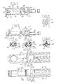
- the manually-adjustable control mechanism 30 is adapted to be used with a rod 31 which is connected to a cable, not shown, and to a service ball 32 which may be connected, for example, to a lever such as a vehicle transmission lever for shifting gears.
- the control mechanism 30 comprises a plastics housing 33 having a longitudinally-extending opening 34 which is rectangular in cross section including a first portion 34a having a greater vertical dimension than the portion 34b communicating with 34a ( Figures 13-19).
- the mechanism 30 further include a plastics locking member 43 which is generally rectangular in cross-section and extends through a rectangular opening 44 in the top wall 45 of the housing 33.
- the locking member 43 includes a top wall or flange 46, spaced side walls 47 ( Figures 20-22).
- a projection 48 extends downwardly from wall 46 of the locking member and includes opposed sides 49 that are inclined downwardly and inwardly on which sets of external teeth 50 are provided for engagement with the internal teeth 41 on the telescopic member 35.
- the locking 43 further includes opposed sets of internal teeth 51 on the internal surfaces of walls 47 for engaging the teeth 42 on the telescopic member 35.
- Housing 33 is provided with laterally-spaced downwardly-projecting cavities 52 that are formed in the bottom wall 53 of housing 33 into which the lower ends of walls 47 of locking member 43 project when the locking member is in the locked position.
- a flexible integral tab 54 is hinged to the wall 46 of locking member 43 and is provided with a recess 55 that engages below the top wall 45 of housing 33 to yieldingly hold the locking member in locked position ( Figure 3).
- Wall 45 includes an inclined surface 56 which facilitates movement of the tab into locking position. By grasping wall 46, the locking member 43 can be moved manually to an unlocked position.
- Inwardly-extending ribs 57 on the inside surfaces of walls 47 of locking member 43 are adapted to engage longitudinally-extending ribs 58 on the telescopic member to retain the locking member 43 when the locking member is moved to unlocked position.
- the walls 47 are adapted to flex past ribs 58 on initial assembly.
- the walls 47 of locking member 43 are provided with a downwardly-extending slot 59 that engage ribs 60 on the inner surface of the side walls 61 of the housing 33 to guide the locking member 43 in its movement between locked position and unlocked position ( Figure 13).
- the telescopic member 35 is guided and supported at its first or forward portion by side ribs 58 which engage the side walls of the smaller portion of housing 33 ( Figures 6, 19) and engage ribs 62 in the larger portion of housing 33 ( Figures 4, 18).
- Telescopic member 35 also includes a longitudinally-extending rib 63 on the bottom surface of the forward portion which engages a complementary groove in the small portion of housing 33 ( Figure 6).
- ribs 58 are laterally enlarged to engage enlarged portions 64 of grooves 62 in the side walls of the enlarged portion of housing 33 ( Figure 5).
- An additional rib 65 on the top of telescopic member 43 engages a complementary groove 66.
- flexible tabs 68 projects laterally outwardly and axially along the end wall 67 of the telescopic member 35 when it is inserted in the housing 33 and engage the teeth 42.
- the telescopic member 35, housing 33 and locking member are made of relatively hard plastic such as glass-filled NYLON (NYLON being a Registered Trade Mark).
Landscapes
- Engineering & Computer Science (AREA)
- General Engineering & Computer Science (AREA)
- Health & Medical Sciences (AREA)
- Oral & Maxillofacial Surgery (AREA)
- Mechanical Engineering (AREA)
- Flexible Shafts (AREA)
- Mechanical Control Devices (AREA)
Applications Claiming Priority (2)
| Application Number | Priority Date | Filing Date | Title |
|---|---|---|---|
| US07/273,259 US4887930A (en) | 1988-11-18 | 1988-11-18 | Manually controlled adjustable locking mechanism for a cable control system |
| US273259 | 1994-07-11 |
Publications (1)
| Publication Number | Publication Date |
|---|---|
| EP0371654A1 true EP0371654A1 (de) | 1990-06-06 |
Family
ID=23043203
Family Applications (1)
| Application Number | Title | Priority Date | Filing Date |
|---|---|---|---|
| EP89311814A Withdrawn EP0371654A1 (de) | 1988-11-18 | 1989-11-15 | Manuell verstellbarer Verschlussmechanismus für ein Stellkabelsystem |
Country Status (4)
| Country | Link |
|---|---|
| US (1) | US4887930A (de) |
| EP (1) | EP0371654A1 (de) |
| JP (1) | JPH02195010A (de) |
| BR (1) | BR8905838A (de) |
Cited By (4)
| Publication number | Priority date | Publication date | Assignee | Title |
|---|---|---|---|---|
| WO1993025824A1 (en) * | 1992-06-05 | 1993-12-23 | Automotive Products Plc | A clutch actuation system and a cable therefor |
| EP1041302A1 (de) * | 1999-03-12 | 2000-10-04 | SILA HOLDING INDUSTRIALE S.r.l. | Anschlussvorrichtung zur Halterung und Einstellung der Spannung eines langgestreckten Körpers, insbesondere eines flexiblen Betätigungszuges |
| DE19800850B4 (de) * | 1998-01-13 | 2007-09-20 | Teleflex Automotive Germany Gmbh | Längseinsteller auf der Seele eines Betätigungszuges |
| CN105723104A (zh) * | 2013-11-28 | 2016-06-29 | Zf腓德烈斯哈芬股份公司 | 具有引导护套和长度补偿的绳索牵拉设备、具有绳索牵拉设备的变速器设施以及用于组装绳索牵拉设备的方法 |
Families Citing this family (25)
| Publication number | Priority date | Publication date | Assignee | Title |
|---|---|---|---|---|
| US5398566A (en) * | 1990-04-26 | 1995-03-21 | Teleflex Incorporated | Manual adjust having oppositely toothed fitting |
| US5241879A (en) * | 1990-07-13 | 1993-09-07 | Teleflex Incorporated | Snap-on fastening device |
| US5220832A (en) * | 1991-09-13 | 1993-06-22 | Teleflex, Incorporated | Oppositely toothed core adjust having integral inner member and control attachment |
| US5163338A (en) * | 1992-02-25 | 1992-11-17 | General Motors Corporation | Cable core length adjuster mechanism |
| US5207116A (en) * | 1992-02-25 | 1993-05-04 | General Motors Corporation | Cable core length adjuster mechanism |
| US5394770A (en) * | 1993-04-08 | 1995-03-07 | Telflex Incorporated | Core length adjuster |
| US5598743A (en) * | 1995-03-24 | 1997-02-04 | Hi-Lex Corporation | Core wire length adjuster |
| US5588334A (en) * | 1995-04-27 | 1996-12-31 | General Motors Corporation | Cable core adjuster with lock members |
| US5571237A (en) * | 1995-04-27 | 1996-11-05 | General Motors Corporation | Cable core adjuster with lock members |
| US5655415A (en) * | 1995-08-02 | 1997-08-12 | Nagle Industries, Inc. | Shift column cable assembly |
| US5605074A (en) * | 1995-09-05 | 1997-02-25 | Teleflex Incorporated | Security collar for adjustable core element terminal |
| ES2140298B1 (es) | 1997-04-23 | 2001-03-01 | Fico Cables Sa | Dispositivo ajustador para cables de mando. |
| JP4028914B2 (ja) * | 1997-08-07 | 2008-01-09 | 中央発條株式会社 | ケーブルジョイント |
| US5934150A (en) * | 1998-01-05 | 1999-08-10 | Teleflex Incorporated | Remote control assembly having a locking terminal |
| US5911791A (en) * | 1998-01-22 | 1999-06-15 | Teleflex Incorporated | Remote control assembly having an improved locking design |
| US6098489A (en) * | 1999-02-15 | 2000-08-08 | Nagle Industries, Inc. | Push-on adjustable cable strand end-fitting |
| DE19941995C2 (de) | 1999-09-02 | 2001-12-06 | Montaplast Gmbh | Längenverstellbares Verbindungselement |
| US6748820B2 (en) * | 2000-11-09 | 2004-06-15 | Dura Global Technologies,Inc. | Self-adjusting isolator for reducing cable lash in transmission shift systems |
| US20060039748A1 (en) | 2002-06-07 | 2006-02-23 | Ruhlander Gregory P | Arrangement for connecting a rod end to a headed pin and method of manufacture |
| JP4798975B2 (ja) * | 2004-08-20 | 2011-10-19 | 株式会社ハイレックスコーポレーション | ケーブル用アジャスト装置およびアジャスト装置付きコントロールケーブル |
| US7779720B2 (en) * | 2005-04-18 | 2010-08-24 | Dura Global Technologies, Llc | Compact core adjuster with vibration dampening |
| US8850920B2 (en) * | 2008-10-10 | 2014-10-07 | Kongsberg Driveline Systems I, Inc. | Adjustment device for a remote control assembly having an easily engageable and disengageable locking element |
| CN102996612A (zh) * | 2011-09-15 | 2013-03-27 | 上海汽车集团股份有限公司 | 一种用于操纵拉索的接头及其使用方法 |
| CN103511439A (zh) * | 2012-06-27 | 2014-01-15 | 德韧干巷汽车系统(上海)有限公司 | 一种拉索可调节装置 |
| JP6367619B2 (ja) * | 2014-06-27 | 2018-08-01 | 株式会社ハイレックスコーポレーション | ケーブル連結装置 |
Citations (3)
| Publication number | Priority date | Publication date | Assignee | Title |
|---|---|---|---|---|
| US4610180A (en) * | 1984-11-28 | 1986-09-09 | Teleflex Incorporated | Motion transmitting remote control assembly--initial reduced resistance self-adjust |
| GB2187528A (en) * | 1986-03-07 | 1987-09-09 | Nippon Cable System Inc | Automatic tension regulating device for remote control wire |
| EP0244067A2 (de) * | 1986-04-28 | 1987-11-04 | Teleflex Incorporated | Handferneinstellung |
Family Cites Families (6)
| Publication number | Priority date | Publication date | Assignee | Title |
|---|---|---|---|---|
| US831981A (en) * | 1903-07-16 | 1906-09-25 | William Hobson | Knob attachment. |
| US2210797A (en) * | 1939-03-14 | 1940-08-06 | Otis P Crim | Knob attaching device |
| US3145720A (en) * | 1962-11-29 | 1964-08-25 | Torii Giichi | Canopy tilting device |
| US3710645A (en) * | 1970-10-08 | 1973-01-16 | Teleflex Inc | Remote control assembly |
| US3662617A (en) * | 1970-10-08 | 1972-05-16 | Teleflex Inc | Remote control assembly |
| US4676119A (en) * | 1985-09-13 | 1987-06-30 | Teleflex Incorporated | Remote control levered self adjust actuator |
-
1988
- 1988-11-18 US US07/273,259 patent/US4887930A/en not_active Expired - Lifetime
-
1989
- 1989-11-15 EP EP89311814A patent/EP0371654A1/de not_active Withdrawn
- 1989-11-17 JP JP1299436A patent/JPH02195010A/ja active Pending
- 1989-11-20 BR BR898905838A patent/BR8905838A/pt unknown
Patent Citations (3)
| Publication number | Priority date | Publication date | Assignee | Title |
|---|---|---|---|---|
| US4610180A (en) * | 1984-11-28 | 1986-09-09 | Teleflex Incorporated | Motion transmitting remote control assembly--initial reduced resistance self-adjust |
| GB2187528A (en) * | 1986-03-07 | 1987-09-09 | Nippon Cable System Inc | Automatic tension regulating device for remote control wire |
| EP0244067A2 (de) * | 1986-04-28 | 1987-11-04 | Teleflex Incorporated | Handferneinstellung |
Cited By (8)
| Publication number | Priority date | Publication date | Assignee | Title |
|---|---|---|---|---|
| WO1993025824A1 (en) * | 1992-06-05 | 1993-12-23 | Automotive Products Plc | A clutch actuation system and a cable therefor |
| GB2273140A (en) * | 1992-06-05 | 1994-06-08 | Automotive Products Plc | A clutch actuation system and a cable therefor |
| US5404981A (en) * | 1992-06-05 | 1995-04-11 | Automotive Products, Plc | Hydraulic clutch actuation system and method of installing |
| GB2273140B (en) * | 1992-06-05 | 1995-06-07 | Automotive Products Plc | A clutch actuation system and a cable therefor |
| DE19800850B4 (de) * | 1998-01-13 | 2007-09-20 | Teleflex Automotive Germany Gmbh | Längseinsteller auf der Seele eines Betätigungszuges |
| EP1041302A1 (de) * | 1999-03-12 | 2000-10-04 | SILA HOLDING INDUSTRIALE S.r.l. | Anschlussvorrichtung zur Halterung und Einstellung der Spannung eines langgestreckten Körpers, insbesondere eines flexiblen Betätigungszuges |
| CN105723104A (zh) * | 2013-11-28 | 2016-06-29 | Zf腓德烈斯哈芬股份公司 | 具有引导护套和长度补偿的绳索牵拉设备、具有绳索牵拉设备的变速器设施以及用于组装绳索牵拉设备的方法 |
| CN105723104B (zh) * | 2013-11-28 | 2019-03-22 | Zf腓德烈斯哈芬股份公司 | 绳索牵拉设备、变速器系统以及制造绳索牵拉设备的方法 |
Also Published As
| Publication number | Publication date |
|---|---|
| BR8905838A (pt) | 1990-06-12 |
| JPH02195010A (ja) | 1990-08-01 |
| US4887930A (en) | 1989-12-19 |
Similar Documents
| Publication | Publication Date | Title |
|---|---|---|
| EP0371654A1 (de) | Manuell verstellbarer Verschlussmechanismus für ein Stellkabelsystem | |
| US5394770A (en) | Core length adjuster | |
| US5207116A (en) | Cable core length adjuster mechanism | |
| US5178034A (en) | Automatic adjust assembly with release pin | |
| EP0223470B1 (de) | Fernbetätigungsvorrichtung mit Seitenrastverriegelung | |
| EP0365242B1 (de) | Handgesteuerte verriegelbare Längenverstellvorrichtung | |
| US5556224A (en) | Shifter handle assembly | |
| CA2055222C (en) | Snap tooth lock device with quick unlock mechanism | |
| GB2273539A (en) | Length-adjusting device for control cable | |
| US5823623A (en) | Guide sleeve for neck rests on vehicle seats | |
| CA2201655C (en) | Serviceable core adjust | |
| US4023435A (en) | Snap fit bowden cable attachment | |
| US5281045A (en) | Movable member positioning mechanism | |
| US5197312A (en) | Cable connector for steering lock device | |
| CA2022528C (en) | Snap-in level vial cover | |
| US20110226082A1 (en) | Shifter base with integrated receptacle for cable adjust assembly | |
| US5791196A (en) | Shifting apparatus for control of a gearbox | |
| US6912973B2 (en) | Automatic cage lock | |
| US4455959A (en) | Apparatus for supporting the mast of a sailing board | |
| CA2183777A1 (en) | Vehicle shifter with mechanically connectable pivot | |
| EP0386617B1 (de) | E-förmiger Haltering | |
| US5253497A (en) | Multi-function automobile steering lock | |
| GB2154723A (en) | Light fitting | |
| CA2140420A1 (en) | Transmission shifter | |
| KR920010893B1 (ko) | 수동 조정식 코어 터미날 |
Legal Events
| Date | Code | Title | Description |
|---|---|---|---|
| PUAI | Public reference made under article 153(3) epc to a published international application that has entered the european phase |
Free format text: ORIGINAL CODE: 0009012 |
|
| AK | Designated contracting states |
Kind code of ref document: A1 Designated state(s): DE ES FR GB IT |
|
| STAA | Information on the status of an ep patent application or granted ep patent |
Free format text: STATUS: THE APPLICATION IS DEEMED TO BE WITHDRAWN |
|
| 18D | Application deemed to be withdrawn |
Effective date: 19901207 |