EP0371655A1 - Séparateur à plaques pour mélanges fluides - Google Patents
Séparateur à plaques pour mélanges fluides Download PDFInfo
- Publication number
- EP0371655A1 EP0371655A1 EP89311828A EP89311828A EP0371655A1 EP 0371655 A1 EP0371655 A1 EP 0371655A1 EP 89311828 A EP89311828 A EP 89311828A EP 89311828 A EP89311828 A EP 89311828A EP 0371655 A1 EP0371655 A1 EP 0371655A1
- Authority
- EP
- European Patent Office
- Prior art keywords
- plate
- plates
- corrugations
- fluid
- coalescing
- Prior art date
- Legal status (The legal status is an assumption and is not a legal conclusion. Google has not performed a legal analysis and makes no representation as to the accuracy of the status listed.)
- Granted
Links
- 239000012530 fluid Substances 0.000 title claims abstract description 30
- 239000000203 mixture Substances 0.000 title description 6
- 125000006850 spacer group Chemical group 0.000 claims abstract description 22
- 238000004140 cleaning Methods 0.000 claims abstract description 11
- 230000002457 bidirectional effect Effects 0.000 claims abstract description 9
- 239000007787 solid Substances 0.000 claims abstract description 8
- 238000000926 separation method Methods 0.000 claims description 9
- XLYOFNOQVPJJNP-UHFFFAOYSA-N water Substances O XLYOFNOQVPJJNP-UHFFFAOYSA-N 0.000 claims description 7
- 230000013011 mating Effects 0.000 claims description 3
- 239000002904 solvent Substances 0.000 claims description 2
- 238000011065 in-situ storage Methods 0.000 abstract description 2
- 239000007921 spray Substances 0.000 description 4
- 239000000463 material Substances 0.000 description 2
- 239000011343 solid material Substances 0.000 description 2
- 230000003467 diminishing effect Effects 0.000 description 1
- 230000000694 effects Effects 0.000 description 1
- 238000002347 injection Methods 0.000 description 1
- 239000007924 injection Substances 0.000 description 1
- 239000012811 non-conductive material Substances 0.000 description 1
- 239000010802 sludge Substances 0.000 description 1
- 239000000126 substance Substances 0.000 description 1
Images

Classifications
-
- B—PERFORMING OPERATIONS; TRANSPORTING
- B01—PHYSICAL OR CHEMICAL PROCESSES OR APPARATUS IN GENERAL
- B01D—SEPARATION
- B01D17/00—Separation of liquids, not provided for elsewhere, e.g. by thermal diffusion
- B01D17/02—Separation of non-miscible liquids
- B01D17/0208—Separation of non-miscible liquids by sedimentation
- B01D17/0211—Separation of non-miscible liquids by sedimentation with baffles
-
- B—PERFORMING OPERATIONS; TRANSPORTING
- B01—PHYSICAL OR CHEMICAL PROCESSES OR APPARATUS IN GENERAL
- B01D—SEPARATION
- B01D21/00—Separation of suspended solid particles from liquids by sedimentation
- B01D21/0039—Settling tanks provided with contact surfaces, e.g. baffles, particles
- B01D21/0045—Plurality of essentially parallel plates
-
- B—PERFORMING OPERATIONS; TRANSPORTING
- B01—PHYSICAL OR CHEMICAL PROCESSES OR APPARATUS IN GENERAL
- B01D—SEPARATION
- B01D21/00—Separation of suspended solid particles from liquids by sedimentation
- B01D21/0039—Settling tanks provided with contact surfaces, e.g. baffles, particles
- B01D21/0069—Making of contact surfaces, structural details, materials therefor
- B01D21/0075—Contact surfaces having surface features
-
- Y—GENERAL TAGGING OF NEW TECHNOLOGICAL DEVELOPMENTS; GENERAL TAGGING OF CROSS-SECTIONAL TECHNOLOGIES SPANNING OVER SEVERAL SECTIONS OF THE IPC; TECHNICAL SUBJECTS COVERED BY FORMER USPC CROSS-REFERENCE ART COLLECTIONS [XRACs] AND DIGESTS
- Y10—TECHNICAL SUBJECTS COVERED BY FORMER USPC
- Y10S—TECHNICAL SUBJECTS COVERED BY FORMER USPC CROSS-REFERENCE ART COLLECTIONS [XRACs] AND DIGESTS
- Y10S210/00—Liquid purification or separation
- Y10S210/05—Coalescer
Definitions
- This invention relates to apparatus for separating immiscible components of different densities mixed in a fluid.
- Plate separators are known which include undulating or corrugated plates stacked in a spaced apart configuration to effect separation. See, for example, U.S. Patent Nos. 3,847,813; 3,957,656; 4,278,545, and 4,299,706.
- substances such as oil which are less dense than a host fluid such as water migrate upwardly while denser components such as solids drift downwardly.
- lighter components such as oil pass heavier solid components after they have reached the separator plate surfaces. In passing, the components often mix once again diminishing the efficiency of the separator. Furthermore, sludge may form which clogs the spaces between the plates.
- a coalescing plate according to the invention has bidirectional corrugations forming crests and valleys in two directions.
- the crests and valleys include bleed holes for passage therethrough of immiscible components mixed with a host fluid.
- Multiple plates may be stacked with spaces between plates maintained by spacers.
- the spacers include asymmetrically located multistep projections and asymmetrically located internal passages adapted for mating with identical spacers such that a 180° rotation of one plate results in a different separation from an adjacent plate.
- the bidirectional corrugations are orthogonal to one another and approximately sinusoidal.
- the wavelength of corrugations in one direction is greater than the wavelength of the corrugations in the other direction, and it is preferred that the direction of fluid flow be parallel to the longer wavelength corrugations.
- Lugs which are removably attached to the lowermost spacer projections are used to provide additional separation between adjacent plates. Plate separation may also be varied in the direction of fluid flow.
- the separator plates of the present invention are readily cleaned in situ by introducing a nozzle through the bleed holes in the plate and into the space between adjacent plates.
- the nozzles are configured to spray fluid substantially parallel to the plate surfaces for effective cleaning.
- the present invention affords numerous advantages over known separators. First of all there is no intermingling of the components after they reach the plate surfaces unlike the configuration in United States Patent 4,278,545. Furthermore, the bidirectional corrugations provide ramps up which the lighter components travel to the upper bleed holes and down which solid and other denser components travel to the bleed holes in the valleys. The bidirectional undulation results in much more surface or collection area per linear dimension of a separator unit.
- Variable spacing between adjacent plates is readily achieved by rotating a plate 180°. Increased spacing is achieved by utilizing additional spacers. Spacing within a separator unit can be varied in the direction of fluid flow to accommodate changes in the mixture composition as the fluid passes through the separator.
- the bidirectional corrugations provide stiffness in two directions thereby requiring fewer supports between adjacent plates. Furthermore, the ramps formed by the corrugations result in shorter collection paths than in known configurations.
- Ease of cleaning the separator stack is another important advantage of the present invention. Prior configurations often had to be disassembled in order to clean them properly.
- the instant invention allows the stack to be cleaned without disassembly.
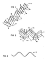
- a corrugated separator plate 10 has corrugations running in orthogonal directions.
- the plate 10 may be made of injection moldable plastic or other suitable material including electrically conductive and non-conductive materials.
- the plates 10 may be stacked in a spaced relationship as shown in Fig. 2.
- the direction of fluid flow is indicated by an arrow 12.
- a trough 14 may be located beneath the valley in the plate 10 to catch solid materials.
- Bleed holes 16 are provided in the crests of the corrugations and bleed holes 18 are provided in the valleys.
- a suitable diameter for bleed holes 16 and 18 is three-quarters of an inch but the diameter may be varied to suit individual requirements. Note that at the edges there are semicircular openings 16a and 18a which form bleed holes when combined with additional separator plates. As shown in Figs. 4 and 5, the corrugations in the orthogonal directions are made up with 45° segments, but the angle can be varied to suit individual requirements.
- Spacers 20 which may be molded integrally with the plate 10 include multistep projections 22 and 24 which are asymmetrically located with respect to a centerline of the spacer 20.
- the spacers 20 also include internal passages 26 and 28 which are also asymmetrically located with respect to the centerline of the spacer 20.
- the separator plate 10 Although the dimensions of the separator plate 10 are not critical, a convenient size has a length of two feet and a width of one foot with three-quarter inch diameter bleed holes. Because of the semicircular openings 16a and 18a at the edges, multiple plates can be abutted to form large separator areas while maintaining the bleed hole pattern. In the exemplary embodiment illustrated in the figures, the distance between the crests and valleys for one corrugation direction is six inches and approximately 2 2/3 inches for the corrugations running in the other direction.
- a stack of separator plates 10 is immersed in a fluid flowing in the direction shown in Fig. 2.
- the host fluid is water mixed with oil and solid material.
- the lighter oil will coalesce and migrate up ramps created by the corrugations and pass through the bleed holes 16 for collection.
- solids and other components denser than water will migrate downwardly and pass through bleed holes 18 and be collected in the trough 14.
- the components reach the respective plate 10 surfaces, they do not substantially intermingle which would diminish the efficiency of the separator.
- the stack of separator plates is turned upside down, the same function will be performed; the bleed holes 16 will now collect the heavier components and bleed holes 18 the lighter components. It may be desirable to decrease the spacing between the plates 10 as the fluid moves downstream as conditions within the mixture will change.
- the invention permits cleaning without having to remove the plates.
- cleaning is effected by passing a tube 40 through one of the bleed holes such as the bleed hole 16 in a crest.
- the tip of the tube 40 includes a nozzle portion 42 which directs a fluid spray downwardly as shown. This downward spray is effective in cleaning the downwardly sloping surfaces.
- a tube 40 may be passed through a bleed hole in a valley and include a nozzle adapted to spray fluid upwardly to clean upward sloping surfaces.
- a suitable cleaning fluid may be the host fluid such as water or a solvent may be used.
Landscapes
- Chemical & Material Sciences (AREA)
- Chemical Kinetics & Catalysis (AREA)
- Physics & Mathematics (AREA)
- Thermal Sciences (AREA)
- Separation Using Semi-Permeable Membranes (AREA)
- Separating Particles In Gases By Inertia (AREA)
- Removal Of Floating Material (AREA)
- Solid-Sorbent Or Filter-Aiding Compositions (AREA)
- Separation Of Solids By Using Liquids Or Pneumatic Power (AREA)
- Fuel Cell (AREA)
Priority Applications (1)
| Application Number | Priority Date | Filing Date | Title |
|---|---|---|---|
| AT89311828T ATE85234T1 (de) | 1988-11-30 | 1989-11-15 | Plattenseparator fuer fluidgemische. |
Applications Claiming Priority (2)
| Application Number | Priority Date | Filing Date | Title |
|---|---|---|---|
| US278000 | 1988-11-30 | ||
| US07/278,000 US4897206A (en) | 1988-11-30 | 1988-11-30 | Bidirectionally corrugated plate separator for fluid mixtures |
Publications (2)
| Publication Number | Publication Date |
|---|---|
| EP0371655A1 true EP0371655A1 (fr) | 1990-06-06 |
| EP0371655B1 EP0371655B1 (fr) | 1993-02-03 |
Family
ID=23063269
Family Applications (1)
| Application Number | Title | Priority Date | Filing Date |
|---|---|---|---|
| EP89311828A Expired - Lifetime EP0371655B1 (fr) | 1988-11-30 | 1989-11-15 | Séparateur à plaques pour mélanges fluides |
Country Status (8)
| Country | Link |
|---|---|
| US (1) | US4897206A (fr) |
| EP (1) | EP0371655B1 (fr) |
| JP (1) | JP2903227B2 (fr) |
| AT (1) | ATE85234T1 (fr) |
| AU (1) | AU627246B2 (fr) |
| CA (1) | CA2001894A1 (fr) |
| DE (1) | DE68904744T2 (fr) |
| ES (1) | ES2038417T3 (fr) |
Cited By (3)
| Publication number | Priority date | Publication date | Assignee | Title |
|---|---|---|---|---|
| DE4212449A1 (de) * | 1992-04-14 | 1993-10-28 | Dyckerhoff & Widmann Ag | Vorrichtung zum Abscheiden suspendierter Stoffe aus einer Flüssigkeit |
| CN103328060A (zh) * | 2010-12-29 | 2013-09-25 | 艾尼股份公司 | 用于具有不同比密度的不可混合相的混合物的聚结分离器 |
| EP2730324B1 (fr) * | 2012-11-07 | 2018-05-30 | KWI International Environmental Treatment GmbH | Séparateur de liquides non-miscibles par coalescence |
Families Citing this family (33)
| Publication number | Priority date | Publication date | Assignee | Title |
|---|---|---|---|---|
| DE3901587A1 (de) * | 1989-01-20 | 1990-07-26 | Krupp Koppers Gmbh | Verfahren zur aufarbeitung des raffinates einer extraktivdestillation von kohlenwasserstoffgemischen |
| DE4103349A1 (de) * | 1991-02-05 | 1992-08-06 | Buderus Bau & Abwassertechnik | Abscheider fuer leichtfluessigkeiten |
| US5229015A (en) * | 1991-05-31 | 1993-07-20 | Nautus, Inc. | Liquid separator |
| US5247878A (en) * | 1992-01-03 | 1993-09-28 | Anderson William H | Device for absorbing liquid lipids from an aqueous food mixture |
| US5203894A (en) * | 1992-04-03 | 1993-04-20 | Munters Corporation | Mist eliminator blade spacer |
| US5411665A (en) * | 1993-07-20 | 1995-05-02 | Scraggs; Charles R. | Methods for reducing and separating emulsions and homogeneous components from contaminated water |
| US5762810A (en) * | 1996-11-22 | 1998-06-09 | Pelton; Paul | Coalescing oil/water separator |
| SE509656C2 (sv) * | 1997-04-15 | 1999-02-22 | Sweden Recycling Ab | Anordning för avskiljning av partiklar ur en vätska |
| US6183634B1 (en) * | 1998-04-02 | 2001-02-06 | Bateman Process Equipment Limited | Separator |
| JP4019554B2 (ja) * | 1998-08-03 | 2007-12-12 | トヨタ自動車株式会社 | 燃料電池セパレータ用多連凹凸板の製造方法 |
| US6056128A (en) * | 1998-08-04 | 2000-05-02 | Glasgow; James A. | Coalescer with removable cartridge |
| US6659290B1 (en) * | 2001-04-05 | 2003-12-09 | The United States Of America As Represented By The Secretary Of The Navy | Oil water separator with air sparging array for in-situ cleaning |
| US6907997B2 (en) * | 2003-02-19 | 2005-06-21 | Hancor, Inc. | Water clarification system with coalescing plates |
| US20050051503A1 (en) * | 2003-09-06 | 2005-03-10 | Holland Robert W. | Coalescer media flexible container and method of use |
| US7470361B2 (en) * | 2003-11-14 | 2008-12-30 | Eberly Christopher N | System for stormwater environmental control |
| RU2272001C2 (ru) * | 2004-04-20 | 2006-03-20 | Общество с ограниченной ответственностью "Севзапналадка" | Коалесцентно-осаждающий элемент |
| US7374668B1 (en) | 2004-11-05 | 2008-05-20 | The United States Of America As Represented By The Secretary Of The Navy | Valve automated in-situ cleaning system for oil water separator |
| CN100333822C (zh) * | 2004-11-24 | 2007-08-29 | 核动力运行研究所 | 干燥器 |
| EP2004950A1 (fr) * | 2006-04-13 | 2008-12-24 | Shell Internationale Research Maatschappij B.V. | Separateur et procede permettant de retirer les solides contenus dans les liquides de forage |
| US20080011693A1 (en) * | 2006-07-12 | 2008-01-17 | Ming Li | Self-cleaning waste-water device and method |
| DE102007056964B4 (de) | 2007-11-27 | 2023-07-20 | Linde Gmbh | Waschkolonne mit Packung im Sumpf der Waschkolonne zur Trennung eines mehrphasigen Flüssigkeitengemisches |
| US8562841B1 (en) * | 2009-03-23 | 2013-10-22 | James Philip Hygate | Glycerine-biodiesel continuous flow separator and methodology of use |
| US8419836B2 (en) * | 2010-02-12 | 2013-04-16 | Hydrotech, Inc. | Gas-liquid separator and related methods |
| AU2012344734A1 (en) * | 2011-12-02 | 2014-07-24 | Envirostream Solutions Pty Ltd | Sediment trap |
| US8985343B1 (en) * | 2014-01-24 | 2015-03-24 | Kirby Smith Mohr | Method and apparatus for separating immiscible liquids and solids from liquids |
| US9868077B2 (en) * | 2014-10-10 | 2018-01-16 | HAMBLEY David M | Method and apparatus for in situ cleaning of tube settlers in water clarification |
| RU2618857C1 (ru) * | 2016-05-18 | 2017-05-11 | Марат Хатимович Газизов | Способ и коалесцентный элемент для разделения эмульсии |
| US20180050944A1 (en) * | 2016-08-16 | 2018-02-22 | Naveed Aslam | Methods for reclaiming produced water |
| US10309089B2 (en) | 2017-02-24 | 2019-06-04 | Advanced Drainage Systems, Inc. | Liquid quality system with drag inducing portions |
| RU186784U1 (ru) * | 2018-07-20 | 2019-02-01 | Рафаиль Кимович Шарипов | Коалесцирующий элемент для разделения водо-нефтяной смеси |
| ES2744323B2 (es) * | 2018-08-24 | 2020-06-25 | Atca Asesoria Proyectos E Instalaciones S L | Lamela para decantador y modulo lamelar para decantador |
| RU206160U1 (ru) * | 2021-06-09 | 2021-08-25 | Федеральное государственное бюджетное образовательное учреждение высшего образования «Казанский государственный энергетический университет» | Устройство для разделения эмульсий с дополнительной деэмульсацией потока |
| CN115317958B (zh) * | 2022-08-10 | 2023-07-25 | 常州大学 | 一种三段式油水分离双维弦波聚结板组装置 |
Citations (4)
| Publication number | Priority date | Publication date | Assignee | Title |
|---|---|---|---|---|
| FR2118609A5 (fr) * | 1970-12-15 | 1972-07-28 | Aspanger Kaolin Steinwer | |
| US3847813A (en) * | 1972-12-27 | 1974-11-12 | Gen Electric | Coalescing plate for fluid mixture plate separator |
| US3957656A (en) * | 1972-04-28 | 1976-05-18 | Castelli Joseph L | Plate separator for fluid mixtures |
| EP0050880A2 (fr) * | 1978-12-19 | 1982-05-05 | Fram Europe Limited | Séparateur d'eau huileuse du type à plaques |
Family Cites Families (15)
| Publication number | Priority date | Publication date | Assignee | Title |
|---|---|---|---|---|
| US3348466A (en) * | 1964-10-16 | 1967-10-24 | Airolite Company | Vertical blade louver |
| US3385439A (en) * | 1966-06-07 | 1968-05-28 | Niels B. Bach | Sedimentation method and apparatus |
| US3741401A (en) * | 1971-11-26 | 1973-06-26 | Neptune Microfloc Inc | Perforated tube module for liquid treatment |
| US3898164A (en) * | 1974-06-24 | 1975-08-05 | Neptune Microfloc Inc | Perforated tube module for liquid treatment |
| CH598855A5 (fr) * | 1975-06-13 | 1978-05-12 | Ciba Geigy Ag | |
| US4133758A (en) * | 1976-09-07 | 1979-01-09 | The Lummus Company | Gravity settling |
| JPS5383157A (en) * | 1976-12-28 | 1978-07-22 | Shinko Pfaudler | Apparatus for suspended material from liquid flow by specific gravity |
| ZA796255B (en) * | 1978-11-24 | 1981-01-28 | Fram Europ | Separation |
| US4278545A (en) * | 1979-09-12 | 1981-07-14 | The Bendix Corporation | Apparatus for separating solids and liquid components |
| US4361426A (en) * | 1981-01-22 | 1982-11-30 | Baltimore Aircoil Company, Inc. | Angularly grooved corrugated fill for water cooling tower |
| US4389315A (en) * | 1981-07-24 | 1983-06-21 | Frank Crocket | Filter device with permeable corrugated grid panel |
| US4437988A (en) * | 1981-08-03 | 1984-03-20 | William James | Plate separator construction and method |
| US4337561A (en) * | 1981-08-03 | 1982-07-06 | William James | Plate separator construction method |
| US4410427A (en) * | 1981-11-02 | 1983-10-18 | Donaldson Company, Inc. | Fluid filtering device |
| US4526691A (en) * | 1982-12-10 | 1985-07-02 | William Melis | Separator apparatus |
-
1988
- 1988-11-30 US US07/278,000 patent/US4897206A/en not_active Expired - Lifetime
-
1989
- 1989-10-31 CA CA002001894A patent/CA2001894A1/fr not_active Abandoned
- 1989-11-15 ES ES198989311828T patent/ES2038417T3/es not_active Expired - Lifetime
- 1989-11-15 AT AT89311828T patent/ATE85234T1/de not_active IP Right Cessation
- 1989-11-15 EP EP89311828A patent/EP0371655B1/fr not_active Expired - Lifetime
- 1989-11-15 DE DE8989311828T patent/DE68904744T2/de not_active Expired - Lifetime
- 1989-11-24 JP JP1303428A patent/JP2903227B2/ja not_active Expired - Fee Related
- 1989-11-27 AU AU45585/89A patent/AU627246B2/en not_active Ceased
Patent Citations (4)
| Publication number | Priority date | Publication date | Assignee | Title |
|---|---|---|---|---|
| FR2118609A5 (fr) * | 1970-12-15 | 1972-07-28 | Aspanger Kaolin Steinwer | |
| US3957656A (en) * | 1972-04-28 | 1976-05-18 | Castelli Joseph L | Plate separator for fluid mixtures |
| US3847813A (en) * | 1972-12-27 | 1974-11-12 | Gen Electric | Coalescing plate for fluid mixture plate separator |
| EP0050880A2 (fr) * | 1978-12-19 | 1982-05-05 | Fram Europe Limited | Séparateur d'eau huileuse du type à plaques |
Cited By (4)
| Publication number | Priority date | Publication date | Assignee | Title |
|---|---|---|---|---|
| DE4212449A1 (de) * | 1992-04-14 | 1993-10-28 | Dyckerhoff & Widmann Ag | Vorrichtung zum Abscheiden suspendierter Stoffe aus einer Flüssigkeit |
| CN103328060A (zh) * | 2010-12-29 | 2013-09-25 | 艾尼股份公司 | 用于具有不同比密度的不可混合相的混合物的聚结分离器 |
| CN103328060B (zh) * | 2010-12-29 | 2015-11-25 | 艾尼股份公司 | 用于具有不同比密度的不可混合相的混合物的聚结分离器 |
| EP2730324B1 (fr) * | 2012-11-07 | 2018-05-30 | KWI International Environmental Treatment GmbH | Séparateur de liquides non-miscibles par coalescence |
Also Published As
| Publication number | Publication date |
|---|---|
| JP2903227B2 (ja) | 1999-06-07 |
| AU627246B2 (en) | 1992-08-20 |
| ATE85234T1 (de) | 1993-02-15 |
| ES2038417T3 (es) | 1993-07-16 |
| AU4558589A (en) | 1990-06-07 |
| DE68904744T2 (de) | 1993-06-17 |
| CA2001894A1 (fr) | 1990-05-31 |
| DE68904744D1 (de) | 1993-03-18 |
| EP0371655B1 (fr) | 1993-02-03 |
| US4897206A (en) | 1990-01-30 |
| JPH02194889A (ja) | 1990-08-01 |
Similar Documents
| Publication | Publication Date | Title |
|---|---|---|
| EP0371655B1 (fr) | Séparateur à plaques pour mélanges fluides | |
| EP0737498B1 (fr) | Plateau de contact gaz-liquide avec éléments de décharge triangulaires ayant des décharges sur les cÔtés | |
| AU737526B2 (en) | Co-current contacting separation tray design and methods for using same | |
| AU718717B2 (en) | Co-current contacting separation tray design and methods for using same | |
| EP0050880A2 (fr) | Séparateur d'eau huileuse du type à plaques | |
| EP0026122A1 (fr) | Dispositif pour la séparation de constituants solides et liquides | |
| CA2096787A1 (fr) | Plateau de fractionnement a deversoirs munis de deflecteurs et a ecoulements paralleles | |
| WO1988006478A1 (fr) | Separateur d'huile-eau | |
| JPH0551340B2 (fr) | ||
| US5188773A (en) | Tower packing with small and large louvers and mixing method | |
| RU2003126959A (ru) | Установка для очистки нефтесодержащих вод | |
| EP1397183B1 (fr) | Appareil de contact gaz/liquide | |
| JPH04268191A (ja) | ルーバーを有する塔パッキング | |
| RU2045333C1 (ru) | Насадка для массообменных аппаратов | |
| CN1045544C (zh) | 气液接触塔 | |
| EP0044301B1 (fr) | Appareil pour la séparation par gravité d'impuretés relativement lourdes et/ou légères d'un courant de liquide | |
| GB2070451A (en) | Baffle plates | |
| SU1666142A1 (ru) | Сепарационный аппарат | |
| CA2146704C (fr) | Plateau de contact gaz-liquide avec deversoirs triangulaires lateraux | |
| SU1033156A1 (ru) | Наклонный отстойник | |
| RU2038113C1 (ru) | Разделитель эмульсии |
Legal Events
| Date | Code | Title | Description |
|---|---|---|---|
| PUAI | Public reference made under article 153(3) epc to a published international application that has entered the european phase |
Free format text: ORIGINAL CODE: 0009012 |
|
| AK | Designated contracting states |
Kind code of ref document: A1 Designated state(s): AT BE CH DE ES FR GB GR IT LI LU NL SE |
|
| 17P | Request for examination filed |
Effective date: 19900925 |
|
| 17Q | First examination report despatched |
Effective date: 19920715 |
|
| GRAA | (expected) grant |
Free format text: ORIGINAL CODE: 0009210 |
|
| AK | Designated contracting states |
Kind code of ref document: B1 Designated state(s): AT BE CH DE ES FR GB GR IT LI LU NL SE |
|
| PG25 | Lapsed in a contracting state [announced via postgrant information from national office to epo] |
Ref country code: GR Free format text: LAPSE BECAUSE OF FAILURE TO SUBMIT A TRANSLATION OF THE DESCRIPTION OR TO PAY THE FEE WITHIN THE PRESCRIBED TIME-LIMIT Effective date: 19930203 Ref country code: BE Effective date: 19930203 Ref country code: SE Effective date: 19930203 |
|
| REF | Corresponds to: |
Ref document number: 85234 Country of ref document: AT Date of ref document: 19930215 Kind code of ref document: T |
|
| REF | Corresponds to: |
Ref document number: 68904744 Country of ref document: DE Date of ref document: 19930318 |
|
| ITF | It: translation for a ep patent filed | ||
| ET | Fr: translation filed | ||
| REG | Reference to a national code |
Ref country code: ES Ref legal event code: FG2A Ref document number: 2038417 Country of ref document: ES Kind code of ref document: T3 |
|
| PG25 | Lapsed in a contracting state [announced via postgrant information from national office to epo] |
Ref country code: LU Free format text: LAPSE BECAUSE OF NON-PAYMENT OF DUE FEES Effective date: 19931130 |
|
| PLBE | No opposition filed within time limit |
Free format text: ORIGINAL CODE: 0009261 |
|
| STAA | Information on the status of an ep patent application or granted ep patent |
Free format text: STATUS: NO OPPOSITION FILED WITHIN TIME LIMIT |
|
| 26N | No opposition filed | ||
| PGFP | Annual fee paid to national office [announced via postgrant information from national office to epo] |
Ref country code: GB Payment date: 20001115 Year of fee payment: 12 |
|
| PG25 | Lapsed in a contracting state [announced via postgrant information from national office to epo] |
Ref country code: GB Free format text: LAPSE BECAUSE OF NON-PAYMENT OF DUE FEES Effective date: 20011115 |
|
| REG | Reference to a national code |
Ref country code: GB Ref legal event code: IF02 |
|
| PGFP | Annual fee paid to national office [announced via postgrant information from national office to epo] |
Ref country code: CH Payment date: 20081125 Year of fee payment: 20 Ref country code: NL Payment date: 20081124 Year of fee payment: 20 |
|
| PGFP | Annual fee paid to national office [announced via postgrant information from national office to epo] |
Ref country code: AT Payment date: 20081021 Year of fee payment: 20 Ref country code: ES Payment date: 20081126 Year of fee payment: 20 |
|
| PGFP | Annual fee paid to national office [announced via postgrant information from national office to epo] |
Ref country code: IT Payment date: 20081126 Year of fee payment: 20 |
|
| PGFP | Annual fee paid to national office [announced via postgrant information from national office to epo] |
Ref country code: FR Payment date: 20081117 Year of fee payment: 20 |
|
| PGFP | Annual fee paid to national office [announced via postgrant information from national office to epo] |
Ref country code: DE Payment date: 20081223 Year of fee payment: 20 |
|
| REG | Reference to a national code |
Ref country code: CH Ref legal event code: PCAR Free format text: AMMANN PATENTANWAELTE AG BERN;SCHWARZTORSTRASSE 31;3001 BERN (CH) |
|
| REG | Reference to a national code |
Ref country code: CH Ref legal event code: PL |
|
| NLV7 | Nl: ceased due to reaching the maximum lifetime of a patent |
Effective date: 20091115 |
|
| REG | Reference to a national code |
Ref country code: ES Ref legal event code: FD2A Effective date: 20091116 |
|
| PG25 | Lapsed in a contracting state [announced via postgrant information from national office to epo] |
Ref country code: NL Free format text: LAPSE BECAUSE OF EXPIRATION OF PROTECTION Effective date: 20091115 |
|
| PG25 | Lapsed in a contracting state [announced via postgrant information from national office to epo] |
Ref country code: ES Free format text: LAPSE BECAUSE OF EXPIRATION OF PROTECTION Effective date: 20091116 |