EP0371759A2 - Einspritzer-Verdichter für gasförmigen Brennstoff für Verdrängermaschinen - Google Patents
Einspritzer-Verdichter für gasförmigen Brennstoff für Verdrängermaschinen Download PDFInfo
- Publication number
- EP0371759A2 EP0371759A2 EP89312355A EP89312355A EP0371759A2 EP 0371759 A2 EP0371759 A2 EP 0371759A2 EP 89312355 A EP89312355 A EP 89312355A EP 89312355 A EP89312355 A EP 89312355A EP 0371759 A2 EP0371759 A2 EP 0371759A2
- Authority
- EP
- European Patent Office
- Prior art keywords
- intensifier
- engine
- chamber
- fuel
- gas
- Prior art date
- Legal status (The legal status is an assumption and is not a legal conclusion. Google has not performed a legal analysis and makes no representation as to the accuracy of the status listed.)
- Withdrawn
Links
Images


Classifications
-
- F—MECHANICAL ENGINEERING; LIGHTING; HEATING; WEAPONS; BLASTING
- F02—COMBUSTION ENGINES; HOT-GAS OR COMBUSTION-PRODUCT ENGINE PLANTS
- F02M—SUPPLYING COMBUSTION ENGINES IN GENERAL WITH COMBUSTIBLE MIXTURES OR CONSTITUENTS THEREOF
- F02M57/00—Fuel-injectors combined or associated with other devices
- F02M57/02—Injectors structurally combined with fuel-injection pumps
- F02M57/022—Injectors structurally combined with fuel-injection pumps characterised by the pump drive
- F02M57/025—Injectors structurally combined with fuel-injection pumps characterised by the pump drive hydraulic, e.g. with pressure amplification
-
- F—MECHANICAL ENGINEERING; LIGHTING; HEATING; WEAPONS; BLASTING
- F02—COMBUSTION ENGINES; HOT-GAS OR COMBUSTION-PRODUCT ENGINE PLANTS
- F02B—INTERNAL-COMBUSTION PISTON ENGINES; COMBUSTION ENGINES IN GENERAL
- F02B23/00—Other engines characterised by special shape or construction of combustion chambers to improve operation
- F02B23/02—Other engines characterised by special shape or construction of combustion chambers to improve operation with compression ignition
- F02B23/06—Other engines characterised by special shape or construction of combustion chambers to improve operation with compression ignition the combustion space being arranged in working piston
- F02B23/0672—Omega-piston bowl, i.e. the combustion space having a central projection pointing towards the cylinder head and the surrounding wall being inclined towards the cylinder center axis
-
- F—MECHANICAL ENGINEERING; LIGHTING; HEATING; WEAPONS; BLASTING
- F02—COMBUSTION ENGINES; HOT-GAS OR COMBUSTION-PRODUCT ENGINE PLANTS
- F02D—CONTROLLING COMBUSTION ENGINES
- F02D19/00—Controlling engines characterised by their use of non-liquid fuels, pluralities of fuels, or non-fuel substances added to the combustible mixtures
- F02D19/06—Controlling engines characterised by their use of non-liquid fuels, pluralities of fuels, or non-fuel substances added to the combustible mixtures peculiar to engines working with pluralities of fuels, e.g. alternatively with light and heavy fuel oil, other than engines indifferent to the fuel consumed
- F02D19/0663—Details on the fuel supply system, e.g. tanks, valves, pipes, pumps, rails, injectors or mixers
- F02D19/0686—Injectors
- F02D19/0694—Injectors operating with a plurality of fuels
-
- F—MECHANICAL ENGINEERING; LIGHTING; HEATING; WEAPONS; BLASTING
- F02—COMBUSTION ENGINES; HOT-GAS OR COMBUSTION-PRODUCT ENGINE PLANTS
- F02M—SUPPLYING COMBUSTION ENGINES IN GENERAL WITH COMBUSTIBLE MIXTURES OR CONSTITUENTS THEREOF
- F02M21/00—Apparatus for supplying engines with non-liquid fuels, e.g. gaseous fuels stored in liquid form
- F02M21/02—Apparatus for supplying engines with non-liquid fuels, e.g. gaseous fuels stored in liquid form for gaseous fuels
- F02M21/0218—Details on the gaseous fuel supply system, e.g. tanks, valves, pipes, pumps, rails, injectors or mixers
- F02M21/0245—High pressure fuel supply systems; Rails; Pumps; Arrangement of valves
-
- F—MECHANICAL ENGINEERING; LIGHTING; HEATING; WEAPONS; BLASTING
- F02—COMBUSTION ENGINES; HOT-GAS OR COMBUSTION-PRODUCT ENGINE PLANTS
- F02M—SUPPLYING COMBUSTION ENGINES IN GENERAL WITH COMBUSTIBLE MIXTURES OR CONSTITUENTS THEREOF
- F02M21/00—Apparatus for supplying engines with non-liquid fuels, e.g. gaseous fuels stored in liquid form
- F02M21/02—Apparatus for supplying engines with non-liquid fuels, e.g. gaseous fuels stored in liquid form for gaseous fuels
- F02M21/0218—Details on the gaseous fuel supply system, e.g. tanks, valves, pipes, pumps, rails, injectors or mixers
- F02M21/0248—Injectors
- F02M21/0251—Details of actuators therefor
-
- F—MECHANICAL ENGINEERING; LIGHTING; HEATING; WEAPONS; BLASTING
- F02—COMBUSTION ENGINES; HOT-GAS OR COMBUSTION-PRODUCT ENGINE PLANTS
- F02M—SUPPLYING COMBUSTION ENGINES IN GENERAL WITH COMBUSTIBLE MIXTURES OR CONSTITUENTS THEREOF
- F02M21/00—Apparatus for supplying engines with non-liquid fuels, e.g. gaseous fuels stored in liquid form
- F02M21/02—Apparatus for supplying engines with non-liquid fuels, e.g. gaseous fuels stored in liquid form for gaseous fuels
- F02M21/0218—Details on the gaseous fuel supply system, e.g. tanks, valves, pipes, pumps, rails, injectors or mixers
- F02M21/0248—Injectors
- F02M21/0257—Details of the valve closing elements, e.g. valve seats, stems or arrangement of flow passages
- F02M21/026—Lift valves, i.e. stem operated valves
- F02M21/0269—Outwardly opening valves, e.g. poppet valves
-
- F—MECHANICAL ENGINEERING; LIGHTING; HEATING; WEAPONS; BLASTING
- F02—COMBUSTION ENGINES; HOT-GAS OR COMBUSTION-PRODUCT ENGINE PLANTS
- F02M—SUPPLYING COMBUSTION ENGINES IN GENERAL WITH COMBUSTIBLE MIXTURES OR CONSTITUENTS THEREOF
- F02M21/00—Apparatus for supplying engines with non-liquid fuels, e.g. gaseous fuels stored in liquid form
- F02M21/02—Apparatus for supplying engines with non-liquid fuels, e.g. gaseous fuels stored in liquid form for gaseous fuels
- F02M21/0218—Details on the gaseous fuel supply system, e.g. tanks, valves, pipes, pumps, rails, injectors or mixers
- F02M21/0248—Injectors
- F02M21/0275—Injectors for in-cylinder direct injection, e.g. injector combined with spark plug
-
- F—MECHANICAL ENGINEERING; LIGHTING; HEATING; WEAPONS; BLASTING
- F02—COMBUSTION ENGINES; HOT-GAS OR COMBUSTION-PRODUCT ENGINE PLANTS
- F02M—SUPPLYING COMBUSTION ENGINES IN GENERAL WITH COMBUSTIBLE MIXTURES OR CONSTITUENTS THEREOF
- F02M43/00—Fuel-injection apparatus operating simultaneously on two or more fuels, or on a liquid fuel and another liquid, e.g. the other liquid being an anti-knock additive
-
- F—MECHANICAL ENGINEERING; LIGHTING; HEATING; WEAPONS; BLASTING
- F02—COMBUSTION ENGINES; HOT-GAS OR COMBUSTION-PRODUCT ENGINE PLANTS
- F02M—SUPPLYING COMBUSTION ENGINES IN GENERAL WITH COMBUSTIBLE MIXTURES OR CONSTITUENTS THEREOF
- F02M49/00—Fuel-injection apparatus in which injection pumps are driven or injectors are actuated, by the pressure in engine working cylinders, or by impact of engine working piston
- F02M49/02—Fuel-injection apparatus in which injection pumps are driven or injectors are actuated, by the pressure in engine working cylinders, or by impact of engine working piston using the cylinder pressure, e.g. compression end pressure
-
- F—MECHANICAL ENGINEERING; LIGHTING; HEATING; WEAPONS; BLASTING
- F02—COMBUSTION ENGINES; HOT-GAS OR COMBUSTION-PRODUCT ENGINE PLANTS
- F02M—SUPPLYING COMBUSTION ENGINES IN GENERAL WITH COMBUSTIBLE MIXTURES OR CONSTITUENTS THEREOF
- F02M59/00—Pumps specially adapted for fuel-injection and not provided for in groups F02M39/00 -F02M57/00, e.g. rotary cylinder-block type of pumps
- F02M59/02—Pumps specially adapted for fuel-injection and not provided for in groups F02M39/00 -F02M57/00, e.g. rotary cylinder-block type of pumps of reciprocating-piston or reciprocating-cylinder type
- F02M59/10—Pumps specially adapted for fuel-injection and not provided for in groups F02M39/00 -F02M57/00, e.g. rotary cylinder-block type of pumps of reciprocating-piston or reciprocating-cylinder type characterised by the piston-drive
- F02M59/107—Pumps specially adapted for fuel-injection and not provided for in groups F02M39/00 -F02M57/00, e.g. rotary cylinder-block type of pumps of reciprocating-piston or reciprocating-cylinder type characterised by the piston-drive pneumatic drive, e.g. crankcase pressure drive
-
- F—MECHANICAL ENGINEERING; LIGHTING; HEATING; WEAPONS; BLASTING
- F02—COMBUSTION ENGINES; HOT-GAS OR COMBUSTION-PRODUCT ENGINE PLANTS
- F02M—SUPPLYING COMBUSTION ENGINES IN GENERAL WITH COMBUSTIBLE MIXTURES OR CONSTITUENTS THEREOF
- F02M63/00—Other fuel-injection apparatus having pertinent characteristics not provided for in groups F02M39/00 - F02M57/00 or F02M67/00; Details, component parts, or accessories of fuel-injection apparatus, not provided for in, or of interest apart from, the apparatus of groups F02M39/00 - F02M61/00 or F02M67/00; Combination of fuel pump with other devices, e.g. lubricating oil pump
- F02M63/001—Fuel-injection apparatus having injection valves held closed mechanically, e.g. by springs, and opened by a cyclically-operated mechanism for a time
-
- F—MECHANICAL ENGINEERING; LIGHTING; HEATING; WEAPONS; BLASTING
- F02—COMBUSTION ENGINES; HOT-GAS OR COMBUSTION-PRODUCT ENGINE PLANTS
- F02M—SUPPLYING COMBUSTION ENGINES IN GENERAL WITH COMBUSTIBLE MIXTURES OR CONSTITUENTS THEREOF
- F02M69/00—Low-pressure fuel-injection apparatus ; Apparatus with both continuous and intermittent injection; Apparatus injecting different types of fuel
- F02M69/04—Injectors peculiar thereto
- F02M69/042—Positioning of injectors with respect to engine, e.g. in the air intake conduit
- F02M69/045—Positioning of injectors with respect to engine, e.g. in the air intake conduit for injecting into the combustion chamber
-
- F—MECHANICAL ENGINEERING; LIGHTING; HEATING; WEAPONS; BLASTING
- F02—COMBUSTION ENGINES; HOT-GAS OR COMBUSTION-PRODUCT ENGINE PLANTS
- F02B—INTERNAL-COMBUSTION PISTON ENGINES; COMBUSTION ENGINES IN GENERAL
- F02B75/00—Other engines
- F02B75/12—Other methods of operation
- F02B2075/125—Direct injection in the combustion chamber for spark ignition engines, i.e. not in pre-combustion chamber
-
- F—MECHANICAL ENGINEERING; LIGHTING; HEATING; WEAPONS; BLASTING
- F02—COMBUSTION ENGINES; HOT-GAS OR COMBUSTION-PRODUCT ENGINE PLANTS
- F02B—INTERNAL-COMBUSTION PISTON ENGINES; COMBUSTION ENGINES IN GENERAL
- F02B23/00—Other engines characterised by special shape or construction of combustion chambers to improve operation
- F02B23/02—Other engines characterised by special shape or construction of combustion chambers to improve operation with compression ignition
- F02B23/06—Other engines characterised by special shape or construction of combustion chambers to improve operation with compression ignition the combustion space being arranged in working piston
- F02B23/0618—Other engines characterised by special shape or construction of combustion chambers to improve operation with compression ignition the combustion space being arranged in working piston having in-cylinder means to influence the charge motion
- F02B23/0621—Squish flow
-
- F—MECHANICAL ENGINEERING; LIGHTING; HEATING; WEAPONS; BLASTING
- F02—COMBUSTION ENGINES; HOT-GAS OR COMBUSTION-PRODUCT ENGINE PLANTS
- F02B—INTERNAL-COMBUSTION PISTON ENGINES; COMBUSTION ENGINES IN GENERAL
- F02B23/00—Other engines characterised by special shape or construction of combustion chambers to improve operation
- F02B23/02—Other engines characterised by special shape or construction of combustion chambers to improve operation with compression ignition
- F02B23/06—Other engines characterised by special shape or construction of combustion chambers to improve operation with compression ignition the combustion space being arranged in working piston
- F02B23/0645—Details related to the fuel injector or the fuel spray
- F02B23/0663—Details related to the fuel injector or the fuel spray having multiple injectors per combustion chamber
-
- F—MECHANICAL ENGINEERING; LIGHTING; HEATING; WEAPONS; BLASTING
- F02—COMBUSTION ENGINES; HOT-GAS OR COMBUSTION-PRODUCT ENGINE PLANTS
- F02B—INTERNAL-COMBUSTION PISTON ENGINES; COMBUSTION ENGINES IN GENERAL
- F02B23/00—Other engines characterised by special shape or construction of combustion chambers to improve operation
- F02B23/02—Other engines characterised by special shape or construction of combustion chambers to improve operation with compression ignition
- F02B23/06—Other engines characterised by special shape or construction of combustion chambers to improve operation with compression ignition the combustion space being arranged in working piston
- F02B23/0645—Details related to the fuel injector or the fuel spray
- F02B23/0669—Details related to the fuel injector or the fuel spray having multiple fuel spray jets per injector nozzle
-
- F—MECHANICAL ENGINEERING; LIGHTING; HEATING; WEAPONS; BLASTING
- F02—COMBUSTION ENGINES; HOT-GAS OR COMBUSTION-PRODUCT ENGINE PLANTS
- F02B—INTERNAL-COMBUSTION PISTON ENGINES; COMBUSTION ENGINES IN GENERAL
- F02B23/00—Other engines characterised by special shape or construction of combustion chambers to improve operation
- F02B23/02—Other engines characterised by special shape or construction of combustion chambers to improve operation with compression ignition
- F02B23/06—Other engines characterised by special shape or construction of combustion chambers to improve operation with compression ignition the combustion space being arranged in working piston
- F02B23/0678—Unconventional, complex or non-rotationally symmetrical shapes of the combustion space, e.g. flower like, having special shapes related to the orientation of the fuel spray jets
- F02B23/069—Unconventional, complex or non-rotationally symmetrical shapes of the combustion space, e.g. flower like, having special shapes related to the orientation of the fuel spray jets characterised by its eccentricity from the cylinder axis
-
- F—MECHANICAL ENGINEERING; LIGHTING; HEATING; WEAPONS; BLASTING
- F02—COMBUSTION ENGINES; HOT-GAS OR COMBUSTION-PRODUCT ENGINE PLANTS
- F02D—CONTROLLING COMBUSTION ENGINES
- F02D19/00—Controlling engines characterised by their use of non-liquid fuels, pluralities of fuels, or non-fuel substances added to the combustible mixtures
- F02D19/06—Controlling engines characterised by their use of non-liquid fuels, pluralities of fuels, or non-fuel substances added to the combustible mixtures peculiar to engines working with pluralities of fuels, e.g. alternatively with light and heavy fuel oil, other than engines indifferent to the fuel consumed
- F02D19/08—Controlling engines characterised by their use of non-liquid fuels, pluralities of fuels, or non-fuel substances added to the combustible mixtures peculiar to engines working with pluralities of fuels, e.g. alternatively with light and heavy fuel oil, other than engines indifferent to the fuel consumed simultaneously using pluralities of fuels
- F02D19/10—Controlling engines characterised by their use of non-liquid fuels, pluralities of fuels, or non-fuel substances added to the combustible mixtures peculiar to engines working with pluralities of fuels, e.g. alternatively with light and heavy fuel oil, other than engines indifferent to the fuel consumed simultaneously using pluralities of fuels peculiar to compression-ignition engines in which the main fuel is gaseous
-
- Y—GENERAL TAGGING OF NEW TECHNOLOGICAL DEVELOPMENTS; GENERAL TAGGING OF CROSS-SECTIONAL TECHNOLOGIES SPANNING OVER SEVERAL SECTIONS OF THE IPC; TECHNICAL SUBJECTS COVERED BY FORMER USPC CROSS-REFERENCE ART COLLECTIONS [XRACs] AND DIGESTS
- Y02—TECHNOLOGIES OR APPLICATIONS FOR MITIGATION OR ADAPTATION AGAINST CLIMATE CHANGE
- Y02T—CLIMATE CHANGE MITIGATION TECHNOLOGIES RELATED TO TRANSPORTATION
- Y02T10/00—Road transport of goods or passengers
- Y02T10/10—Internal combustion engine [ICE] based vehicles
- Y02T10/12—Improving ICE efficiencies
-
- Y—GENERAL TAGGING OF NEW TECHNOLOGICAL DEVELOPMENTS; GENERAL TAGGING OF CROSS-SECTIONAL TECHNOLOGIES SPANNING OVER SEVERAL SECTIONS OF THE IPC; TECHNICAL SUBJECTS COVERED BY FORMER USPC CROSS-REFERENCE ART COLLECTIONS [XRACs] AND DIGESTS
- Y02—TECHNOLOGIES OR APPLICATIONS FOR MITIGATION OR ADAPTATION AGAINST CLIMATE CHANGE
- Y02T—CLIMATE CHANGE MITIGATION TECHNOLOGIES RELATED TO TRANSPORTATION
- Y02T10/00—Road transport of goods or passengers
- Y02T10/10—Internal combustion engine [ICE] based vehicles
- Y02T10/30—Use of alternative fuels, e.g. biofuels
Definitions
- This invention relates to a novel device for compressing and injecting gaseous fuel from a variable pressure gaseous fuel supply into a fuel receiving apparatus. More particularly, this invention relates to an intensifier-injector which compresses and injects gaseous fuel from a variable pressure source into the cylinder of a positive displacement engine.
- the problem could also in principle be alleviated by preheating the air at part load; however this may adversely affect turbo-charger operation and increase the danger of detonation.
- a control system would be required to adjust the heating rate with load and speed and it is questionable whether at low load the exhaust heat available would be sufficient.
- timed port injection An alternative method, "timed port injection”, has been proposed for injection of natural gas into two-stroke diesel engines.
- the objective is to time the injection of natural gas into the inlet port so as to avoid wasted gas leaving with the exhaust and (ideally) at low load to have the gas stratified within the cylinder so that it can burn acceptably after compression and diesel pilot ignition. So far, this method to the applicants' knowledge has not proven capable of high efficiency, durable, clean operation over a wide range of load and speeds and with high levels of fuel substitution.
- the gaseous fuel for these engines was available at a constant high pressure.
- the natural gas was stored in liquid form (LNG), then pumped to high pressure and vaporized to give gaseous injection pressures of 5000 psi (340 atm.).
- the gas injector valve replaced the diesel injector and a small diesel injector was installed in the "test-cock" hole in the cylinder head.
- Full rated power was achieved with less than 2% pilot diesel fuel (98% natural gas) and thermal efficiency was slightly lower than 100% diesel operation.
- the Norwegian work carried out under the direction of Professor Arthur Saarsten at Trondheim, involved the direct injection of methane gas into a large bore (300 mm) two-stroke single-cylinder engine.
- the injection pressure was in the range 150-160 atm.
- the diesel injector was left unmodified and a hole was bored in the cylinder head for a gas injection valve.
- thermal efficiencies were slightly better than when running with 100% diesel oil.
- gas injection gave only slightly higher smoke reading than with 100% diesel and NOx emissions were reduced about 24%.
- the gas was injected at about 250 atm.
- the pilot diesel fuel was injected through a separate diesel injection system. With as low as 5% diesel pilot fuel energy input, the overall efficiency at 85% of engine load was the same as with full diesel fueling. An improved fuel injection nozzle with integral injection of the diesel pilot fuel also provided satisfactory performance. The overall result was that "almost equal" performance was obtained with natural gas fueling as with 100% diesel operation.
- liquid form With the natural gas stored on the vehicle in liquid form (LNG), i.e. at very low temperatures in a well insulated tank, the liquid can be readily compressed (and probably vaporized) before injection into the engine cylinder.
- LNG liquid form
- CNG compressed natural gas
- a problem for transport engines is that the gas will not be available at a constant supply pressure.
- the safe upper limit for gas storage will be about 200 atm, which is near the required injection pressure.
- the pressure will have to be allowed to drop to about 20 atm before refueling.
- the energy required to recompress from 20 atm to 200 would be a small part of what is required for the compression from 1 atm to 200. Provision of an external compressor on the vehicle requires substantial capital cost and provision of an additional drive i.e. substantial engine modification.
- the CNG must be compressed to operating levels, particularly when the pressure of the CNG drops to relatively low levels. Provision of an external compressor on the vehicle requires substantial capital cost. An auxiliary drive must also be provided which requires substantial engine modification.
- U.S. Patent 4406404 discloses a method of injecting fuel into the combustion chamber of a diesel engine cylinder. Included is a plunger mounted in a nozzle body to define an air chamber for receiving compressed air from the combustion chamber during the compression stroke of the piston in the engine cylinder. Formed integral with the plunger, a needle valve defines within the nozzle body a fuel chamber for receiving fuel to be injected. A nozzle tip secured to the nozzle body founds a premixing chamber open directly to the combustion chamber and further in communication with both air chamber and fuel chamber. Thus, upon descent of the plunger at the end of the compression stroke, the fuel from the fuel chamber is intimately premixed in the premixing chamber with the compressed air from the air chamber, prior to introduction into the combustion chamber.
- Horino et al specify that "the fuel from the fuel chamber is intimately premixed within the premixing chamber with the compressed air from the air chamber prior to introduction into the combustion chamber". Thus premixing, and a premixing chamber are required, the fuel and air are not mixed in the engine chamber;
- the Horino et al device relates to "diesel fuel” only. There is no mention of natural gas or of dealing with the essential problem of how to compress and inject a gaseous fuel into a compression-ignition engine;
- Horino et al do not mention a pilot injection of liquid diesel fuel (or other means) which is required to assist in compression ignition of the natural gas. They also do not mention an intensifier mechanism.
- U.S. Patent 4201160 "Fuel Injection Systems", Fenne and Greenford, May 6, 1980, discloses a fuel injection system for supplying fuel to a combustion space of an internal combustion engine.
- This includes a fuel injection nozzle having a fuel inlet and outlets which direct fuel into the combustion space.
- a piston is provided with a cylinder, one end of which is subjected to the pressure within the combustion space.
- the other end of the cylinder communicates with the inlet of the nozzle and a valve is provided whereby a fuel injection pump is held out of communication with the inlet of the nozzle until the piston has moved inwardly under the action of rising pressure within the combustion chamber.
- fuel injection pump is held out of communication with the inlet of the nozzle until the piston has moved inwardly under the action of rising pressure within the combustion chamber.
- fuel is displaced by the piston to the nozzle and this is supplied as a pilot quantity of fuel to the combustion space.
- Fenne et al disclose that the fuel injector is a supplementary injector to provide early injection of a small portion of the fuel requirement, see "the main quantity of fuel being supplied by the main pump to the nozzle". All of the fuel is not delivered by a single unit.
- Fenne et al do not mention gaseous fuel nor do they include provision for intensifying the fuel pressure (i.e. increasing the fuel pressure to at least twice the pressure of the compressed air which actuates the intensifier).
- the invention is a new device for compression and injection of gaseous fuel from a variable pressure supply (along with possible use of an entrained liquid fuel which could serve as an ignition source) into the cylinder of an internal combustion engine. If entrained liquid fuel is desired for ignition, the gas injection at high velocity could atomize the liquid fuel.
- the primary application of the invention is to compression ignition (diesel) engines but secondary fields of application are spark, catalytic surface, and hot surface ignition engines.
- the invention involves a method and an intensifier-injector for gaseous fuels in internal combustion engines comprising means which utilizes a compressed gas or fluid to drive an intensifier means which raises the pressure of fuel gas supplied to the internal combustion engine for rapid injection into the cylinder of the internal combustion engine.
- Sources of the intensifier drive gas or fluid include, but are not limited to: compressed air or combustion gas from the cylinder of the internal combustion engine; compressed air from an external compressor, e.g. airbrake compressor; high pressure diesel fuel; pressurized lube oil; air compressed by a turbocharger or supercharger; or compressed freon from an air-conditioning compressor.
- the invention pertains to an apparatus as defined, wherein the internal combustion engine is a positive displacement engine.
- gaseous fuel is drawn from a variable pressure gaseous fuel supply.
- the subject invention represents a novel advance over present technology in that it enables compression to high pressure of a gaseous fuel from a variable pressure source to be attained without the need for an external high-pressure compressor. It does this by using a portion of compressed air, obtained during the compression stroke, or possibly combustion gas, to drive an intensifier which singly or in association with supplemental cam-actuated compression raises the pressure of the fuel gas sufficiently for rapid gas injection into the engine cylinder.
- the intensifier can also be driven by an available low pressure compressed air supply such as is commonly used for vehicle air brakes.
- the system can be used with "gas blast" pilot liquid fuel injection.
- the invention is not limited to pilot liquid fuel ignition, but can coexist with glow plug or spark-assisted ignition.
- One purpose of the invention is to permit high-efficiency low-pollution use of gaseous fuels in diesel engines, while preserving the advantages of high compression ratio non-throttling operation.
- the invention can be used for direct replacement of liquid injectors in road and rail diesels as well as off-highway truck and marine diesels with gaseous fuel injectors from on-board compressed gas storage tanks, or for stationary applications where the gas supply pressure is less than, say, 200 atm.
- Several versions of the invention are feasible for simple replacement of injectors without the need for engine modifications other than control system adaptation.
- Other versions are suitable for new designs of diesel engine heads.
- compressed gas or high pressure combustion gas
- an intensifier to compress the natural gas fuel to a pressure sufficiently high for injection into the cylinder.
- the volume of the intensifier is dependent on the volume of CNG entering the intensifier. At 20 atm and 300 K the CNG will have a density of
- the stoichiometric fuel-air mass ratio for methane is 1:17.16 kg/kg so a maximum mass injection quantity, per stroke, of natural gas is about M g ⁇ M a /20 ⁇ 0.00007 kg
- the maximum compressed air pressure is of the order of 80 -100 atm, so the air-side piston diameter must be of an order ⁇ 200/100 times the gas side piston diameter, or about 20 mm. Allowing for 2 mm wall thickness, the intensifier outer diameter is 24 mm.
- the displacement on the air side of the intensifier is about 11000 mm3 which is about 1.1% of the engine piston displacement, or about 20% of the clearance volume.
- the engine turbocharger may need to compensate for the lower compression pressure.
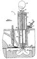
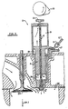
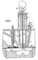
- Figures 1, 2 and 3 show in schematic form, roughly to scale, one mechanical embodiment of the intensifier 2 and its operational sequence.
- the intensifier illustrated in Figure 1 (adapted for use with a diesel engine) has two moving parts, namely an intensifier piston 4 and a hollow gas injector valve stem 6 which supplies compressed air through compressed air inlet 7 to the top surface of the intensifier piston 4 (as shown by directional arrows).
- a nozzle 8 at the bottom of the intensifier 2 is closed and compressed gas from the engine chamber 26, caused by rising piston 24, is admitted to the chamber 9 above the intensifier piston 4 via hollow stem 6 and inlet 15.
- Figure 1 shows the compressed gas from the engine chamber 26 entering the intensifier through inlet 7 and to the top of the piston 4 by inlet 15 and pushing piston 4 down.
- the intensifier piston 4 moves downwards in the interior cylinder 16 of the intensifier 2 thereby compressing the gas in cylinder 16, which is trapped by the check valve 12, thereby building the gas pressure in the chamber 16 to as high as 200 atm.
- Diesel fuel is supplied to the chamber 26 through an inlet 17.
- the gas injection valve 14 is opened by downward mechanical, hydraulic, pneumatic or electromagnetic actuation of its stem 6.
- a cam 19 is shown in Figures 1, 2 and 3, and pushes stem 6 downwardly a distance indicated at the top of Figure 2 by hitting plate 21. This suddenly releases the gas pressure in chamber 16 through the nozzle opening 8 while simultaneously closing off the compressed gas from the engine chamber 26 through channel 16 via inlet 15 to the top of the intensifier piston 4.
- Fuel injection into chamber 26 is illustrated by plumes of droplets 20.
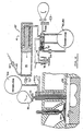
- Figures 4, 5 and 6 show three other embodiments of the intensifier-injector invention.
- Figure 4 displays a variation of the injection nozzle arrangement, with no perforated hemispherical bulb 28 below the valve 14. A bulb 28 may not be necessary in certain situations.
- Figure 5 shows an alternative intensifier piston 4 arrangement.
- the piston 4 as seen in Figure 5 is inverted, which in certain instances may be attractive for performance purposes.
- the gas supply inlet 10 is located at a higher elevation in this embodiment.
- Figure 6 illustrates an external accumulator 30 in conjunction with the intensifier-injector 2.
- the accumulator 30 may be advisable in certain situations to provide a larger compressed gas capacity.
- Figure 6 also illustrates a line 32 which has a check valve 34 and enables the pressure in chamber 26 to communicate with chamber 9. This is used instead of hollow stem 6 and inlet 15.
- Figure 7 shows a separate diesel injector 36 coupled with an intensifier-injector 2.
- FIG 8 shows an embodiment of the invention wherein the intensifier piston 4 is driven by differential pressures on its two unequal-area piston faces 38 and 40.
- the pressures are derived from an accumulator/high-pressure storage tank 42 which in turn receives post-ignition high-pressure gas from the engine combustion chamber 26 through a one-way check valve 44.
- These high-pressure stored gases are directed by a sliding spool valve 46 which is actuated by cam 19.
- This cam 19 is synchronized with the engine crank (not shown) and cam duration may be adjusted during engine operation to account for various required load levels.
- the fuel gas trapped under the small-area side 40 of the intensifier piston is compressed before being released into the combustion chamber 26 through a pressure relief valve 48 set at about 200 atmospheres.
- This system though more complex than that shown in the previously discussed embodiments, should offer quicker intensifier piston response and movement due to the higher pressures available from the gas storage tank 42 and the quick acting sliding spool valve 46.
- Figures 9 and 10 disclose alternative embodiments incorporating the same theme.
- Figure 9 illustrates a single intensifier unit 50 for single- or multiple-cylinder engines (though it is not limited by this application) which receives differential pressures on its two piston faces 52 and 54.
- the narrow protrusion 56 from the face 52 of the piston 51 pushes the sealing ball valve 58 off its seat thus allowing high-pressure gas from the compressed gas storage tank 60 to enter into the chamber 53 when the piston 51 is near top dead center (as seen in Figure 9).
- the expanded gases in the other chamber ss are allowed to exit the chamber through a port 62 cut into the side of the cylinder 50. This same port 62 serves both chambers.
- Figure 9 also shows a check valve 68 and return line 70 which permit gas in chamber 55 to pass to tank 60 when activated by protrusion 66.
- the larger area piston 51 acts directly towards compressing the fuel gas at the far end of the chamber 55.
- This compressed fuel gas passes through one-way check valve 72 and is stored in an accumulator/high-pressure storage tank 64 where individual fuel supply lines (only one supply line 17 is shown) provide high-pressure fuel gas to individual engine chambers (not shown).
- Each engine chamber has a dual-fuel injector which is operated by a cam 19 or other means.
- the intensifier piston 51 oscillates at a speed independent of engine speed, though it may slow down when the engine slows down due to less availability of high-pressure gas from the engine cylinders. While this embodiment is relatively simple, an auxiliary mechanism may be required to start the piston oscillations when the engine is started.
- This "embodiment" should offer easy adaptation to existing hardware since the intensifier and tanks may be located away from the limited-space engine chamber area.
- FIG 10 The embodiment illustrated in Figure 10 is similar to that shown in Figure 9, but the intensifier 67 is controlled by a cam 69 actuated sliding spool valve 71.
- This mechanism is very similar to that shown in Figure 8 and the same description applies and should be readily understandable to a person skilled in the art.
- the high-pressure fuel gas is stored and distributed from a tank 64. Also, each chamber has its own dual-fuel injector.
- the embodiment illustrated in Figure 11 is similar to that shown in Figure 9, but the intensifier is driven by compressed air from an external compressor 73 (e.g. an air-brake or air-starter compressor).
- an external compressor 73 e.g. an air-brake or air-starter compressor.
- the embodiment illustrated in Figure 12 is similar to that shown in Figure 11, but the intensifier is driven by pressurized fluid (e.g. diesel or lube oil) from an external pump 74. Fluid is returned to the reservoir 78 by the spool valve 71 through the return line 77.
- pressurized fluid e.g. diesel or lube oil
- FIG 13 The embodiment illustrated in Figure 13 is similar to that shown in Figure 9, but the compressed gas from the engine cylinder chamber for driving the intensifier is provided by way of a port 75 in the engine cylinder head external to the injector.
- the embodiment illustrated in Figure 14 is similar to that shown in Figure 12, but the intensifier is driven by high pressure fluid (e.g. diesel or lube oil) from an cam driven plunger 75.
- the high pressure fluid acts on the small area end of the intensifier piston to compress the fuel gas existing in the follow chamber of the large area end of the intensifier piston.
- Exhausted fluid is returned to the reservoir 78 by the spool valve 71 through the return line 77.
Landscapes
- Engineering & Computer Science (AREA)
- Chemical & Material Sciences (AREA)
- Combustion & Propulsion (AREA)
- Mechanical Engineering (AREA)
- General Engineering & Computer Science (AREA)
- Oil, Petroleum & Natural Gas (AREA)
- Chemical Kinetics & Catalysis (AREA)
- General Chemical & Material Sciences (AREA)
- Analytical Chemistry (AREA)
- Output Control And Ontrol Of Special Type Engine (AREA)
- Fuel-Injection Apparatus (AREA)
Applications Claiming Priority (4)
| Application Number | Priority Date | Filing Date | Title |
|---|---|---|---|
| CA584496 | 1988-11-29 | ||
| CA000584496A CA1321110C (en) | 1988-11-29 | 1988-11-29 | Intensifier-injector for gaseous fuel for positive displacement engine |
| US07/441,104 US5067467A (en) | 1988-11-29 | 1989-11-27 | Intensifier-injector for gaseous fuel for positive displacement engines |
| US441104 | 1989-11-27 |
Publications (2)
| Publication Number | Publication Date |
|---|---|
| EP0371759A2 true EP0371759A2 (de) | 1990-06-06 |
| EP0371759A3 EP0371759A3 (de) | 1990-08-22 |
Family
ID=25672261
Family Applications (1)
| Application Number | Title | Priority Date | Filing Date |
|---|---|---|---|
| EP89312355A Withdrawn EP0371759A3 (de) | 1988-11-29 | 1989-11-29 | Einspritzer-Verdichter für gasförmigen Brennstoff für Verdrängermaschinen |
Country Status (2)
| Country | Link |
|---|---|
| US (1) | US5315973A (de) |
| EP (1) | EP0371759A3 (de) |
Cited By (10)
| Publication number | Priority date | Publication date | Assignee | Title |
|---|---|---|---|---|
| EP0520659A1 (de) * | 1991-06-25 | 1992-12-30 | Oy Wartsila Diesel International Ltd. | Kraftstoffeinspritzventil und mit diesem ausgestatteter Motor |
| EP0546985A1 (de) * | 1991-12-10 | 1993-06-16 | New Sulzer Diesel Ag | Brennstoffeinspritzventil für eine Hubkolbenbrennkraftmaschine für wahlweisen Betrieb mit Dieselöl oder mit einem gasförmigen Brennstoff |
| WO1995012067A1 (fr) * | 1993-10-25 | 1995-05-04 | Melchior Jean F | Dispositif d'injection de combustible liquide pour moteur diesel, et moteur diesel comprenant ce dispositif |
| US5531199A (en) * | 1992-05-11 | 1996-07-02 | United Fuels Limited | Internal combustion engines |
| FR2792370A1 (fr) * | 1999-04-14 | 2000-10-20 | Hidraulik Ring Gmbh | Dispositif d'injection pour moteurs a combustion interne |
| DE10052336A1 (de) * | 2000-10-22 | 2002-05-02 | Gvh Entwicklungsgesellschaft F | Brennkraftmaschine mit Einblasung von gasförmigem Kraftstoff |
| US6845746B2 (en) | 2000-10-22 | 2005-01-25 | Westport Germany Gmbh | Internal combustion engine with injection of gaseous fuel |
| US7040281B2 (en) | 2000-10-22 | 2006-05-09 | Westport Research Inc. | Method of injecting a gaseous fuel into an internal combustion engine |
| FR2891014A1 (fr) * | 2005-09-20 | 2007-03-23 | Renault Sas | Injecteur mixte pour carburants gazeux et liquides et procede d'injection |
| US7281515B2 (en) | 2000-10-22 | 2007-10-16 | Westport Power Inc. | Method of injecting a gaseous fuel into an internal combustion engine |
Families Citing this family (71)
| Publication number | Priority date | Publication date | Assignee | Title |
|---|---|---|---|---|
| US20030012985A1 (en) | 1998-08-03 | 2003-01-16 | Mcalister Roy E. | Pressure energy conversion systems |
| WO1992008886A1 (en) * | 1990-11-20 | 1992-05-29 | Biocom Pty. Ltd. | A method of fuel injection |
| DE4422552C1 (de) * | 1994-06-28 | 1995-11-30 | Daimler Benz Ag | Verfahren zum Einspritzen von Kraftstoff in den Brennraum einer Brennkraftmaschine |
| US5501200A (en) * | 1994-06-28 | 1996-03-26 | Bogartz; Stuart P. | Compressed gas fueling system |
| US5499615A (en) * | 1994-10-28 | 1996-03-19 | Caterpillar Inc. | Direct injection propane fuel system for diesel engine applications |
| DK174242B1 (da) * | 1996-01-15 | 2002-10-14 | Man B & W Diesel As | Fremgangsmåde til styring af brændselstilførslen til en dieselmotor, der ved højtryksindsprøjtningbåde kan tilføres brændselsolie og brændselsgas, og en højtryks gasindsprøjtningsmotor af dieseltypen |
| AU4082997A (en) | 1996-08-23 | 1998-03-26 | Cummins Engine Company Inc. | Homogeneous charge compression ignition engine with optimal combustion control |
| US6230683B1 (en) | 1997-08-22 | 2001-05-15 | Cummins Engine Company, Inc. | Premixed charge compression ignition engine with optimal combustion control |
| RU2126908C1 (ru) * | 1997-04-28 | 1999-02-27 | Российский Университет Дружбы Народов | Система топливоподачи газодизеля с внутренним смесеобразованием |
| CA2204983A1 (en) * | 1997-05-09 | 1998-11-09 | Westport Research Inc. | Hydraulically actuated gaseous or dual fuel injector |
| CN1292153C (zh) | 1998-02-23 | 2006-12-27 | 卡明斯发动机公司 | 带有优化燃烧控制的预混合充量压缩点火发动机 |
| US6045054A (en) * | 1998-04-23 | 2000-04-04 | Siemens Automotive Corporation | Air shroud for air assist fuel injector |
| US5870978A (en) * | 1998-05-15 | 1999-02-16 | Caterpillar Inc. | Dual fuel engine which utilizes valve lubricant as a pilot fuel |
| US6032617A (en) * | 1998-05-27 | 2000-03-07 | Caterpillar Inc. | Dual fuel engine which ignites a homogeneous mixture of gaseous fuel, air, and pilot fuel |
| JP2002518627A (ja) * | 1998-06-18 | 2002-06-25 | エフ・エー・フアウ・モトーレンテヒニック・ゲゼルシヤフト・ミト・ベシユレンクテル・ハフツング | 点火ガスの吹き込みによって多気筒往復ピストン型ガス機関を点火する方法 |
| US6336598B1 (en) | 1998-09-16 | 2002-01-08 | Westport Research Inc. | Gaseous and liquid fuel injector with a two way hydraulic fluid control valve |
| US6095102A (en) * | 1998-10-02 | 2000-08-01 | Caterpillar Inc. | Dual fuel engine which creates a substantially homogeneous mixture of gaseous fuel, air, and pilot fuel during a compression stroke |
| US6298825B1 (en) | 1998-11-27 | 2001-10-09 | Fev Motorentechnik Gmbh | Method for igniting a multi-cylinder reciprocating gas engine by injecting an ignition gas |
| EP1218634A1 (de) * | 1999-06-11 | 2002-07-03 | Giuliano Cozzari | Direkteinspritzsystem für brennkraftmaschinen und verfahren dafür |
| GB9914646D0 (en) * | 1999-06-24 | 1999-08-25 | Lucas Ind Plc | Fuel injector |
| US6234153B1 (en) * | 1999-10-11 | 2001-05-22 | Daimlerchrysler Corporation | Purge assisted fuel injection |
| US6314947B1 (en) * | 1999-10-13 | 2001-11-13 | Walbro Corporation | Fuel delivery system |
| US6360963B2 (en) | 2000-01-12 | 2002-03-26 | Woodward Governor Company | Gaseous fuel injector having high heat tolerance |
| US6270024B1 (en) | 2000-01-12 | 2001-08-07 | Woodward Governor Company | Hydraulically actuated fuel injector cartridge and system for high pressure gaseous fuel injection |
| US6260776B1 (en) | 2000-01-12 | 2001-07-17 | Woodward Governor Company | Universal gaseous fuel injector cartridge |
| US6675748B2 (en) | 2000-02-11 | 2004-01-13 | Westport Research Inc. | Method and apparatus for fuel injection into an internal combustion engine |
| US6202601B1 (en) * | 2000-02-11 | 2001-03-20 | Westport Research Inc. | Method and apparatus for dual fuel injection into an internal combustion engine |
| US6328222B1 (en) | 2000-04-25 | 2001-12-11 | Siemens Automotive Corporation | Pulsed air assist valve module |
| US6427660B1 (en) * | 2000-07-20 | 2002-08-06 | Ford Global Technologies, Inc. | Dual fuel compression ignition engine |
| DE10065266A1 (de) * | 2000-12-29 | 2002-07-18 | Bosch Gmbh Robert | Verfahren, Computerprogramm sowie Steuer- und/oder Regelgerät zum Betreiben einer Brennkraftmaschine und Brennkraftmaschine |
| US6601566B2 (en) | 2001-07-11 | 2003-08-05 | Caterpillar Inc | Fuel injector with directly controlled dual concentric check and engine using same |
| US6725838B2 (en) | 2001-10-09 | 2004-04-27 | Caterpillar Inc | Fuel injector having dual mode capabilities and engine using same |
| US6439202B1 (en) | 2001-11-08 | 2002-08-27 | Cummins Inc. | Hybrid electronically controlled unit injector fuel system |
| US6857263B2 (en) | 2002-08-08 | 2005-02-22 | The United States Of America As Represented By The Administrator Of The Environmental Protection Agency | Low emission diesel combustion system with low charge-air oxygen concentration levels and high fuel injection pressures |
| US6786194B2 (en) * | 2002-10-31 | 2004-09-07 | Hewlett-Packard Development Company, L.P. | Variable fuel delivery system and method |
| US7032566B2 (en) * | 2003-05-30 | 2006-04-25 | Caterpillar Inc. | Fuel injector nozzle for an internal combustion engine |
| US6988492B2 (en) * | 2003-06-12 | 2006-01-24 | Michael Shetley | Hydrogen and liquid fuel injection system |
| DE10328166A1 (de) * | 2003-06-24 | 2005-01-13 | Daimlerchrysler Ag | Brennstoffzuführsystem und Einblasventil für eine Brennkraftmaschine |
| US7438039B2 (en) | 2004-02-06 | 2008-10-21 | Electro-Motive Diesel, Inc. | Large-bore, medium-speed diesel engine having piston crown bowl with acute re-entrant angle |
| JP4119864B2 (ja) * | 2004-03-31 | 2008-07-16 | 三菱重工業株式会社 | 内燃機関の燃料噴射装置 |
| GB2413824A (en) * | 2004-05-07 | 2005-11-09 | Statoil Asa | Operating diesel-cycle i.c. engines on gaseous fuels with ignition-improvers |
| FR2872224A1 (fr) * | 2004-06-29 | 2005-12-30 | Renault Sas | Dispositif d'injection de carburant sous pression pour un moteur a combustion interne |
| US7044103B2 (en) * | 2004-08-16 | 2006-05-16 | Dresser, Inc. | Fuel quantity modulation in pilot ignited engines |
| DE102005005958A1 (de) * | 2005-02-10 | 2006-08-17 | Volkswagen Ag | Brennkraftmaschine mit Gasbetrieb |
| WO2007090019A2 (en) * | 2006-01-27 | 2007-08-09 | Gm Global Technology Operations, Inc. | Method and apparatus for a spark-ignited direct injection engine |
| CA2532775C (en) * | 2006-01-31 | 2008-04-15 | Westport Research Inc. | Method and apparatus for delivering two fuels to a direct injection internal combustion engine |
| US8108128B2 (en) * | 2009-03-31 | 2012-01-31 | Dresser, Inc. | Controlling exhaust gas recirculation |
| US8616177B2 (en) * | 2010-02-11 | 2013-12-31 | Wisconsin Alumni Research Foundation | Engine combustion control via fuel reactivity stratification |
| FI122492B (fi) * | 2010-06-11 | 2012-02-15 | Waertsilae Finland Oy | Polttomoottorin ohjaus |
| US8851045B2 (en) | 2011-03-31 | 2014-10-07 | Wisconsin Alumni Research Foundation | Engine combustion control at low loads via fuel reactivity stratification |
| US8434462B2 (en) * | 2011-10-18 | 2013-05-07 | Chi Keng “George” Chen | Direct gas injection system for four stroke internal combustion engine |
| US9057321B2 (en) | 2012-01-24 | 2015-06-16 | Wisconsin Alumni Research Foundation | Fuel reactivity stratification in rotary diesel engines |
| US9255560B2 (en) * | 2013-03-15 | 2016-02-09 | Mcalister Technologies, Llc | Regenerative intensifier and associated systems and methods |
| US9091204B2 (en) | 2013-03-15 | 2015-07-28 | Mcalister Technologies, Llc | Internal combustion engine having piston with piston valve and associated method |
| US20140366577A1 (en) * | 2013-06-18 | 2014-12-18 | Pioneer Energy Inc. | Systems and methods for separating alkane gases with applications to raw natural gas processing and flare gas capture |
| US9541032B2 (en) * | 2014-05-16 | 2017-01-10 | Adsorbed Natural Gas Products, Inc. | Sorbent-based low pressure gaseous fuel delivery system |
| US9828987B2 (en) * | 2015-01-30 | 2017-11-28 | Caterpillar Inc. | System and method for priming a pump |
| CN107636285B (zh) * | 2015-04-09 | 2021-07-02 | 西港能源有限公司 | 用于气体燃料发动机中的预混混合气的点火设备以及方法 |
| RU2591360C1 (ru) * | 2015-06-23 | 2016-07-20 | Анатолий Александрович Рыбаков | Способ управления подачей топлива в камеру сгорания двигателя внутреннего сгорания однотактным приводом топливной форсунки |
| US9915235B2 (en) | 2015-10-02 | 2018-03-13 | Wisconsin Alumni Research Foundation | Engine combustion control at high loads via fuel reactivity stratification |
| EP3421765B1 (de) * | 2016-11-25 | 2020-09-30 | Mazda Motor Corporation | Brennkraftmaschine mit kompressionszündung |
| DE102017114390B3 (de) * | 2017-06-28 | 2018-11-08 | Maximilian Bierl | Gaseinbringvorrichtung, Verbrennungsmotor und Betriebsverfahren |
| DE102017012222B4 (de) | 2017-06-28 | 2021-07-22 | Maximilian Bierl | Gaseinbringvorrichtung, Verbrennungsmotor und Betriebsverfahren |
| US10113696B1 (en) | 2017-06-30 | 2018-10-30 | Adsorbed Natural Gas Products, Inc. | Integrated on-board low-pressure adsorbed natural gas storage system for an adsorbed natural gas vehicle |
| US11008932B2 (en) * | 2018-01-12 | 2021-05-18 | Transportation Ip Holdings, Llc | Engine mixing structures |
| US11125147B2 (en) | 2019-06-11 | 2021-09-21 | Caterpillar Inc. | Prechamber ignition system having hydraulically actuated piston |
| RU2742622C1 (ru) * | 2020-09-03 | 2021-02-09 | Анатолий Александрович Рыбаков | Способ привода топливной форсунки двигателя внутреннего сгорания жидкостным возвратно-поступательным электроприводом |
| US11725619B2 (en) | 2021-02-23 | 2023-08-15 | Transportation Ip Holdings, Llc | Alignment system and associated method |
| US11608803B2 (en) | 2021-07-07 | 2023-03-21 | Transportation Ip Holdings, Llc | Insert device for fuel injection |
| US11781469B2 (en) | 2021-08-12 | 2023-10-10 | Transportation Ip Holdings, Llc | Insert device for fuel injection |
| CN115013205A (zh) * | 2022-05-25 | 2022-09-06 | 莆田市宏业精密机械有限公司 | 一种电控柴油机气缸内压缩气体增压的高压喷射装置 |
Family Cites Families (20)
| Publication number | Priority date | Publication date | Assignee | Title |
|---|---|---|---|---|
| BE548434A (de) * | ||||
| NL46694C (de) * | 1936-04-18 | |||
| FR1136373A (fr) * | 1955-09-08 | 1957-05-13 | Perfectionnements apportés aux dispositifs d'injection de combustible dans des moteurs à combustion interne | |
| GB1303065A (de) * | 1969-05-08 | 1973-01-17 | ||
| FR2211598B1 (de) * | 1972-12-20 | 1976-04-30 | Cav Ltd | |
| US3996906A (en) * | 1975-04-24 | 1976-12-14 | General Motors Corporation | Controlled exhaust gas fuel atomizing nozzle |
| US4112899A (en) * | 1976-02-04 | 1978-09-12 | Allied Chemical Corporation | Pressurizing fuel ram air charger |
| US4091772A (en) * | 1976-05-14 | 1978-05-30 | Cooper Industries, Inc. | Internal combustion engine with delayed torch ignition of oil fuel charge |
| GB1599400A (en) * | 1977-06-09 | 1981-09-30 | Lucas Industries Ltd | Fuel injection systems for internal combustion engines |
| BE889978A (fr) * | 1981-08-14 | 1981-12-01 | Santoro Vito | Moteur thermique a injection de carburant et de comburant |
| DE3133288A1 (de) * | 1981-08-22 | 1983-03-03 | M.A.N. Maschinenfabrik Augsburg-Nürnberg AG, 8900 Augsburg | "brennstoffeinspritzsystem an einer brennkraftmaschine" |
| CA1209196A (en) * | 1983-04-11 | 1986-08-05 | John D. Ridley | Ignition source for internal combustion engine |
| CH671609A5 (de) * | 1985-06-24 | 1989-09-15 | Mitsui Shipbuilding Eng | Vorrichtung zum verhindern eines uebermaessigen durchflusses von gasfoermigem brennstoff durch eine einspritzduese eines dieselmotors. |
| US4742801A (en) * | 1987-08-13 | 1988-05-10 | Erik Kelgard | Dual fuel mobil engine system |
| US4831982A (en) * | 1987-09-08 | 1989-05-23 | Baranescu George S | Internal combustion engine with broad fuel tolerance |
| IT1213756B (it) * | 1987-12-28 | 1989-12-29 | Sprint Auto Spa | Impianto perfezionato per l'alimentazione promiscua di motori a ciclo otto ad iniezione elettronica |
| US4865001A (en) * | 1988-11-28 | 1989-09-12 | Energy Conversions, Inc. | Gaseous fuel injector valve |
| CA1321110C (en) * | 1988-11-29 | 1993-08-10 | Philip G. Hill | Intensifier-injector for gaseous fuel for positive displacement engine |
| US5190216A (en) * | 1991-04-19 | 1993-03-02 | Deneke Carl F | Fuel-injection apparatus for internal combustion engines |
| US5136986A (en) * | 1991-04-26 | 1992-08-11 | Energy Conversions, Inc. | Dual fuel injection structure |
-
1989
- 1989-11-29 EP EP89312355A patent/EP0371759A3/de not_active Withdrawn
-
1991
- 1991-11-22 US US07/797,442 patent/US5315973A/en not_active Expired - Lifetime
Cited By (13)
| Publication number | Priority date | Publication date | Assignee | Title |
|---|---|---|---|---|
| EP0520659A1 (de) * | 1991-06-25 | 1992-12-30 | Oy Wartsila Diesel International Ltd. | Kraftstoffeinspritzventil und mit diesem ausgestatteter Motor |
| EP0546985A1 (de) * | 1991-12-10 | 1993-06-16 | New Sulzer Diesel Ag | Brennstoffeinspritzventil für eine Hubkolbenbrennkraftmaschine für wahlweisen Betrieb mit Dieselöl oder mit einem gasförmigen Brennstoff |
| US5531199A (en) * | 1992-05-11 | 1996-07-02 | United Fuels Limited | Internal combustion engines |
| WO1995012067A1 (fr) * | 1993-10-25 | 1995-05-04 | Melchior Jean F | Dispositif d'injection de combustible liquide pour moteur diesel, et moteur diesel comprenant ce dispositif |
| FR2711736A1 (fr) * | 1993-10-25 | 1995-05-05 | Melchior Jean F | Dispositif d'injection de combustible liquide pour moteur Diesel. |
| FR2792370A1 (fr) * | 1999-04-14 | 2000-10-20 | Hidraulik Ring Gmbh | Dispositif d'injection pour moteurs a combustion interne |
| DE10052336A1 (de) * | 2000-10-22 | 2002-05-02 | Gvh Entwicklungsgesellschaft F | Brennkraftmaschine mit Einblasung von gasförmigem Kraftstoff |
| DE10052336B4 (de) * | 2000-10-22 | 2004-04-22 | Westport Germany Gmbh | Brennkraftmaschine mit Einblasung von gasförmigem Kraftstoff |
| US6845746B2 (en) | 2000-10-22 | 2005-01-25 | Westport Germany Gmbh | Internal combustion engine with injection of gaseous fuel |
| US6854438B2 (en) | 2000-10-22 | 2005-02-15 | Westport Germany Gmbh | Internal combustion engine with injection of gaseous fuel |
| US7040281B2 (en) | 2000-10-22 | 2006-05-09 | Westport Research Inc. | Method of injecting a gaseous fuel into an internal combustion engine |
| US7281515B2 (en) | 2000-10-22 | 2007-10-16 | Westport Power Inc. | Method of injecting a gaseous fuel into an internal combustion engine |
| FR2891014A1 (fr) * | 2005-09-20 | 2007-03-23 | Renault Sas | Injecteur mixte pour carburants gazeux et liquides et procede d'injection |
Also Published As
| Publication number | Publication date |
|---|---|
| US5315973A (en) | 1994-05-31 |
| EP0371759A3 (de) | 1990-08-22 |
Similar Documents
| Publication | Publication Date | Title |
|---|---|---|
| US5067467A (en) | Intensifier-injector for gaseous fuel for positive displacement engines | |
| EP0371759A2 (de) | Einspritzer-Verdichter für gasförmigen Brennstoff für Verdrängermaschinen | |
| US6073862A (en) | Gaseous and liquid fuel injector | |
| US5996558A (en) | Hydraulically actuated gaseous or dual fuel injector | |
| US11255260B2 (en) | Variable compression ratio engines and methods for HCCI compression ignition operation | |
| US6336598B1 (en) | Gaseous and liquid fuel injector with a two way hydraulic fluid control valve | |
| US6427660B1 (en) | Dual fuel compression ignition engine | |
| US8327831B2 (en) | Dual fuel compression ignition engines and methods | |
| US7954472B1 (en) | High performance, low emission engines, multiple cylinder engines and operating methods | |
| US11073070B2 (en) | Liquid and gaseous multi-fuel compression ignition engines | |
| US4240381A (en) | Internal combustion engine system | |
| US7954478B1 (en) | Airless engine | |
| WO2019027800A2 (en) | DIESEL ENGINE WITH TURBULENT JET IGNITION | |
| JP2016079973A (ja) | 燃料バルブ及び内燃エンジンの燃料室にガス燃料を噴射する方法 | |
| US4300486A (en) | Internal combustion engine system technical field | |
| US20180100469A1 (en) | Dual Fuel Ammonia Combustion in Diesel Engines | |
| US5899188A (en) | Air fuel vapor stratifier | |
| Stan | Direct injection systems: the next decade in engine technology | |
| JP2871317B2 (ja) | ガスエンジンにおける燃料供給装置 | |
| US12234782B1 (en) | Dual fuel engine system having fuel-actuated unit pumps and method | |
| KR101121453B1 (ko) | 혼소 엔진 | |
| CN113915037A (zh) | 一种具有双喷射系统的二冲程发动机 |
Legal Events
| Date | Code | Title | Description |
|---|---|---|---|
| PUAI | Public reference made under article 153(3) epc to a published international application that has entered the european phase |
Free format text: ORIGINAL CODE: 0009012 |
|
| AK | Designated contracting states |
Kind code of ref document: A2 Designated state(s): AT BE CH DE ES FR GB GR IT LI LU NL SE |
|
| PUAL | Search report despatched |
Free format text: ORIGINAL CODE: 0009013 |
|
| AK | Designated contracting states |
Kind code of ref document: A3 Designated state(s): AT BE CH DE ES FR GB GR IT LI LU NL SE |
|
| 17P | Request for examination filed |
Effective date: 19910102 |
|
| 17Q | First examination report despatched |
Effective date: 19910603 |
|
| STAA | Information on the status of an ep patent application or granted ep patent |
Free format text: STATUS: THE APPLICATION IS DEEMED TO BE WITHDRAWN |
|
| 18D | Application deemed to be withdrawn |
Effective date: 19920811 |