EP0371923A1 - Fusspedalschalter für elektrische Maschinen - Google Patents
Fusspedalschalter für elektrische Maschinen Download PDFInfo
- Publication number
- EP0371923A1 EP0371923A1 EP89810886A EP89810886A EP0371923A1 EP 0371923 A1 EP0371923 A1 EP 0371923A1 EP 89810886 A EP89810886 A EP 89810886A EP 89810886 A EP89810886 A EP 89810886A EP 0371923 A1 EP0371923 A1 EP 0371923A1
- Authority
- EP
- European Patent Office
- Prior art keywords
- pedal
- machine
- foot
- handle
- housing
- Prior art date
- Legal status (The legal status is an assumption and is not a legal conclusion. Google has not performed a legal analysis and makes no representation as to the accuracy of the status listed.)
- Granted
Links
- 238000009958 sewing Methods 0.000 claims description 8
- 230000004913 activation Effects 0.000 description 1
- 239000004744 fabric Substances 0.000 description 1
Images
Classifications
-
- D—TEXTILES; PAPER
- D05—SEWING; EMBROIDERING; TUFTING
- D05B—SEWING
- D05B69/00—Driving-gear; Control devices
- D05B69/14—Devices for changing speed or for reversing direction of rotation
- D05B69/18—Devices for changing speed or for reversing direction of rotation electric, e.g. foot pedals
-
- H—ELECTRICITY
- H01—ELECTRIC ELEMENTS
- H01H—ELECTRIC SWITCHES; RELAYS; SELECTORS; EMERGENCY PROTECTIVE DEVICES
- H01H21/00—Switches operated by an operating part in the form of a pivotable member acted upon directly by a solid body, e.g. by a hand
- H01H21/02—Details
- H01H21/18—Movable parts; Contacts mounted thereon
- H01H21/22—Operating parts, e.g. handle
- H01H21/24—Operating parts, e.g. handle biased to return to normal position upon removal of operating force
- H01H21/26—Operating parts, e.g. handle biased to return to normal position upon removal of operating force adapted for operation by a part of the human body other than the hand, e.g. by foot
Definitions
- Control pedals are known for an electrical machine, in particular for a sewing machine, comprising a housing and a movable member shaped to be actuated by the foot of the user, this member acting on a variable electrical element allowing the activation and adjustment of the machine speed, an electric cord being provided to connect the pedal to the machine.
- the present invention aims to make pedals of this kind more practical to use.
- the pedal which is the subject of the invention is characterized in that said member is in the form of a handle capable of occupying two positions, one of which is used for transporting the pedal and the other for controlling the speed of the machine.
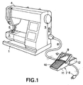
- the sewing machine shown in FIG. 1 usually comprises a base 1, a lower arm 2, an upright 3 and an upper arm 4 carrying a fabric press 5.
- the supply of this electric machine is done by means of a plug 6 intended to be engaged in an outlet of the distribution network, the current being brought to a control pedal 7, which is connected by an electric cord 8 to the electric motor. that the sewing machine contains.
- the pedal 7 has a movable member 9 intended to be actuated by the foot of the user, the heel of which normally rests on a support plate 10. This member 9 allows the machine to start up and its speed to be adjusted. sewing.
- the pedal 7 comprises a housing 11 and, on two lateral faces of this housing, a portion 12 forming a coil to allow the cord carrying the plug 6 to be wound therein, the cord 8 respectively.
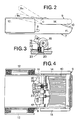
- FIG. 2 shows the pedal 7 in the non-use position, in which the member 9, which is in the form of a handle, is folded over the plate 10. It can also be seen that the electrical cord 8 has been wound around its portion forming a coil. Finally, FIG. 2 also shows in phantom, the two extreme positions of the member 9 for the position of use, namely the position 9a corresponding to the stopping of the machine and the position 9b corresponding to its maximum speed. .
- the movable member 9 is U-shaped comprising a central branch 13 and two lateral branches 14, the free ends of the latter being connected together by a rod 15.
- This rod pivots in support bearings 16 and 17 integral with the side walls of the housing 11.
- the rod 15 carries two cams 18 and 19.
- the cam 18 acts on a switch 20 and is shaped to act on the switch in order to interrupt the supply of the machine, as soon as the member 9 is moved from its position 9a to be brought into its position allowing transport and storing the pedal when not in use. This provides a higher level of safety, making it possible to avoid any untimely start-up of the machine, for example, in the event of a fault in an electrical element supplying the motor.
- the other cam 19 has the shape of a finger acting on the rod 21, such as a potentiometer, this rod being returned upwards by a spring 22 housed in a housing 23.
- the rod 15 still carries a disc 24 having a blind bore 25, in which is housed a ball 26 subjected to the action of a spring 27, this ball is engaged with a recess 28 of the bearing 16.
- This arrangement forms an elastic notch to maintain the member 9 in its transport position.
- control pedal has been described with reference to use for a sewing machine, but it goes without saying that it can be used for any device or machine whose operation is to be controlled using a foot pedal. ordered.
Landscapes
- Engineering & Computer Science (AREA)
- Mechanical Engineering (AREA)
- Textile Engineering (AREA)
- Sewing Machines And Sewing (AREA)
- Mechanical Control Devices (AREA)
- Arrangement And Mounting Of Devices That Control Transmission Of Motive Force (AREA)
Applications Claiming Priority (2)
| Application Number | Priority Date | Filing Date | Title |
|---|---|---|---|
| CH4412/88A CH676530A5 (de) | 1988-11-28 | 1988-11-28 | |
| CH4412/88 | 1988-11-28 |
Publications (2)
| Publication Number | Publication Date |
|---|---|
| EP0371923A1 true EP0371923A1 (de) | 1990-06-06 |
| EP0371923B1 EP0371923B1 (de) | 1993-07-07 |
Family
ID=4275659
Family Applications (1)
| Application Number | Title | Priority Date | Filing Date |
|---|---|---|---|
| EP89810886A Expired - Lifetime EP0371923B1 (de) | 1988-11-28 | 1989-11-20 | Fusspedalschalter für elektrische Maschinen |
Country Status (14)
| Country | Link |
|---|---|
| US (1) | US5083069A (de) |
| EP (1) | EP0371923B1 (de) |
| JP (1) | JPH02182290A (de) |
| CN (1) | CN1024577C (de) |
| AU (1) | AU625728B2 (de) |
| BR (1) | BR8905981A (de) |
| CA (1) | CA2003967A1 (de) |
| CH (1) | CH676530A5 (de) |
| DD (1) | DD289858A5 (de) |
| DE (1) | DE68907469T2 (de) |
| ES (1) | ES2042065T3 (de) |
| PT (1) | PT92417B (de) |
| SU (1) | SU1766267A3 (de) |
| ZA (1) | ZA898421B (de) |
Cited By (1)
| Publication number | Priority date | Publication date | Assignee | Title |
|---|---|---|---|---|
| US8184457B2 (en) | 2006-07-27 | 2012-05-22 | Koninklijke Philips Electronics N.V. | Switch mode power supply for in-line voltage applications |
Families Citing this family (8)
| Publication number | Priority date | Publication date | Assignee | Title |
|---|---|---|---|---|
| US6064015A (en) * | 1997-10-14 | 2000-05-16 | Conntrol, International, Inc. | Foot switches |
| JP2007229291A (ja) * | 2006-03-02 | 2007-09-13 | Brother Ind Ltd | 刺繍ミシン |
| US8794650B2 (en) | 2012-08-09 | 2014-08-05 | Jefferson S Williams | Hands free bicycle maintenance pedaler |
| CN102995315B (zh) * | 2012-11-26 | 2015-07-22 | 吴江市科时达纺织有限公司 | 一种缝纫机踏板装置 |
| US9657865B2 (en) | 2015-06-12 | 2017-05-23 | Federal Signal Corporation | Two-stage valve actuation system |
| CN104911840A (zh) * | 2015-06-23 | 2015-09-16 | 杰克缝纫机股份有限公司 | 一种以脚踏板控制电机转速的装置 |
| CN110485073A (zh) * | 2018-05-15 | 2019-11-22 | 丰田纺织株式会社 | 缝纫机 |
| US11062859B1 (en) * | 2019-07-22 | 2021-07-13 | Itool Equipment Holding Llc | Foot switch-including adaptor assembly for battery-powered hand tool |
Citations (5)
| Publication number | Priority date | Publication date | Assignee | Title |
|---|---|---|---|---|
| FR1469594A (fr) * | 1966-01-06 | 1967-02-17 | Pédale de télécommande de machine ou machine-outil combinant une très grande simplicité de construction à une grande sécurité d'utilisation | |
| DE1588913A1 (de) * | 1967-07-18 | 1970-12-23 | Dentaltechnik Potsdam Veb | Betaetigungseinrichtung zum Anlasser,insbesondere fuer Motoren im zahntechnischen Labor |
| FR2456378A1 (fr) * | 1979-05-07 | 1980-12-05 | Reiter John | Dispositif de securite pour appareil electrique |
| US4296702A (en) * | 1978-03-23 | 1981-10-27 | Dorina Nahmaschinen Gmbh | Storage compartment for sewing machine foot controller |
| US4751354A (en) * | 1987-03-02 | 1988-06-14 | Molded Parts Specialists | Electric outboard motor control switch |
Family Cites Families (12)
| Publication number | Priority date | Publication date | Assignee | Title |
|---|---|---|---|---|
| US1728004A (en) * | 1926-03-31 | 1929-09-10 | Gen Electric | Rheostat |
| US2192714A (en) * | 1937-05-20 | 1940-03-05 | Stewart Warner Corp | Electric throttle control |
| US2644868A (en) * | 1950-07-31 | 1953-07-07 | Lenora H Allison | Safety switch |
| US2846552A (en) * | 1954-10-09 | 1958-08-05 | Pfaff Ag G M | Plural-purpose controller for electric sewing machines and the like |
| US2822441A (en) * | 1956-02-23 | 1958-02-04 | Grant S Fortney | Protector cover |
| US2944120A (en) * | 1958-06-12 | 1960-07-05 | Zorro D Ruben | Safety foot switch |
| US3427545A (en) * | 1967-11-09 | 1969-02-11 | Mercury Electric Products Mfg | Carbon-pile rheostat of the foot operated type |
| US3898542A (en) * | 1974-04-01 | 1975-08-05 | Singer Co | Sewing machine motor speed controller assembly |
| US3916722A (en) * | 1974-10-17 | 1975-11-04 | Square D Co | Treadle operated control |
| JPS5533057A (en) * | 1978-08-30 | 1980-03-08 | Yamamoto Electric Ind Co Ltd | Motor speed controller |
| US4283612A (en) * | 1980-05-05 | 1981-08-11 | Baltimore Aircoil Co., Inc. | Machine guarding apparatus |
| US4496811A (en) * | 1983-04-15 | 1985-01-29 | Lawrence Irwin F | Foot switch safety enclosure |
-
1988
- 1988-11-28 CH CH4412/88A patent/CH676530A5/fr not_active IP Right Cessation
-
1989
- 1989-11-02 CN CN89108397A patent/CN1024577C/zh not_active Expired - Fee Related
- 1989-11-06 ZA ZA898421A patent/ZA898421B/xx unknown
- 1989-11-20 EP EP89810886A patent/EP0371923B1/de not_active Expired - Lifetime
- 1989-11-20 ES ES198989810886T patent/ES2042065T3/es not_active Expired - Lifetime
- 1989-11-20 DE DE89810886T patent/DE68907469T2/de not_active Expired - Fee Related
- 1989-11-23 SU SU894742416A patent/SU1766267A3/ru active
- 1989-11-24 JP JP1303432A patent/JPH02182290A/ja active Pending
- 1989-11-27 DD DD89334891A patent/DD289858A5/de not_active IP Right Cessation
- 1989-11-27 CA CA002003967A patent/CA2003967A1/fr not_active Abandoned
- 1989-11-27 PT PT92417A patent/PT92417B/pt not_active IP Right Cessation
- 1989-11-28 AU AU45596/89A patent/AU625728B2/en not_active Ceased
- 1989-11-28 BR BR898905981A patent/BR8905981A/pt unknown
-
1991
- 1991-02-22 US US07/659,448 patent/US5083069A/en not_active Expired - Fee Related
Patent Citations (5)
| Publication number | Priority date | Publication date | Assignee | Title |
|---|---|---|---|---|
| FR1469594A (fr) * | 1966-01-06 | 1967-02-17 | Pédale de télécommande de machine ou machine-outil combinant une très grande simplicité de construction à une grande sécurité d'utilisation | |
| DE1588913A1 (de) * | 1967-07-18 | 1970-12-23 | Dentaltechnik Potsdam Veb | Betaetigungseinrichtung zum Anlasser,insbesondere fuer Motoren im zahntechnischen Labor |
| US4296702A (en) * | 1978-03-23 | 1981-10-27 | Dorina Nahmaschinen Gmbh | Storage compartment for sewing machine foot controller |
| FR2456378A1 (fr) * | 1979-05-07 | 1980-12-05 | Reiter John | Dispositif de securite pour appareil electrique |
| US4751354A (en) * | 1987-03-02 | 1988-06-14 | Molded Parts Specialists | Electric outboard motor control switch |
Cited By (1)
| Publication number | Priority date | Publication date | Assignee | Title |
|---|---|---|---|---|
| US8184457B2 (en) | 2006-07-27 | 2012-05-22 | Koninklijke Philips Electronics N.V. | Switch mode power supply for in-line voltage applications |
Also Published As
| Publication number | Publication date |
|---|---|
| CH676530A5 (de) | 1991-01-31 |
| JPH02182290A (ja) | 1990-07-16 |
| PT92417A (pt) | 1990-05-31 |
| PT92417B (pt) | 1995-08-09 |
| AU625728B2 (en) | 1992-07-16 |
| DE68907469T2 (de) | 1993-11-04 |
| CN1024577C (zh) | 1994-05-18 |
| DD289858A5 (de) | 1991-05-08 |
| DE68907469D1 (de) | 1993-08-12 |
| CA2003967A1 (fr) | 1990-05-28 |
| SU1766267A3 (ru) | 1992-09-30 |
| BR8905981A (pt) | 1990-06-19 |
| ES2042065T3 (es) | 1993-12-01 |
| ZA898421B (en) | 1990-06-27 |
| AU4559689A (en) | 1990-05-31 |
| CN1043173A (zh) | 1990-06-20 |
| EP0371923B1 (de) | 1993-07-07 |
| US5083069A (en) | 1992-01-21 |
Similar Documents
| Publication | Publication Date | Title |
|---|---|---|
| EP1551261B1 (de) | Elektrischer wasserkocher | |
| FR2707935A1 (fr) | Appareil pour l'entraînement d'un siège motorisé de véhicule. | |
| EP0371923B1 (de) | Fusspedalschalter für elektrische Maschinen | |
| WO2001019225A2 (fr) | Batteur-mixeur electrique a main | |
| EP2433534A1 (de) | Haushaltsgerät mit einem Gefäss das ein von einem Motor angetriebenes Schneidewerkzeug umfasst | |
| EP2368469B1 (de) | Elektrohaushaltsgerät zur Essenzubereitung, das ein Motorgehäuse zur Aufnahme von verschiedenen Typen von auswechselbaren Zubehörteilen umfasst | |
| EP0681307B1 (de) | Sicherheitsvorrichtung für ein elektrisches bewegliches Bauelement und Grill mit einer derartigen Vorrichtung | |
| EP2337046A1 (de) | Vorrichtung zur Steuerung eines Trennschalters eines Haushaltsgeräts | |
| FR2599550A1 (fr) | Commutateur pour vehicules automobiles | |
| WO1990002505A1 (fr) | Dispositif pour bercer mecaniquement les jeunes enfants | |
| FR2481514A1 (fr) | Dispositif de rappel automatique par manque de tension de la commande d'un commutateur rotatif | |
| FR2464047A1 (fr) | Dispositif de securite pour un appareil culinaire | |
| CA2168169A1 (fr) | Dispositif de mise en oeuvre d'un procede de nettoyage de la paroi interne d'un bol d'un appareil electromenager | |
| EP0557206B1 (de) | Programmschaltwerk mit einem Steuerungssystem für schrittweise Betätigung | |
| FR2662236A1 (fr) | Dispositif economiseur pour table de cuisson a gaz. | |
| FR2594453A1 (fr) | Dispositif de protection pour une machine electrique a couper les tissus | |
| FR2544220A2 (fr) | Agitateur de sang | |
| CH303314A (fr) | Appareil de contrôle. | |
| FR2657453A1 (fr) | Equipement pour poste de travail, en particulier pour poste informatique. | |
| CH261700A (fr) | Machine à graver. | |
| FR2705311A3 (fr) | Dispositif de commande pour le freinage dans des conditions de stationnement de véhicules à moteur équipés du changement automatique de vitesse. | |
| CH221123A (fr) | Appareil téléphonique. | |
| FR2642865A1 (fr) | Programmateur a dispositif d'affichage a preselection | |
| BE336528A (de) | ||
| FR2808467A1 (fr) | Appareil electrique de traitement d'aliments comportant un organe presseur |
Legal Events
| Date | Code | Title | Description |
|---|---|---|---|
| PUAI | Public reference made under article 153(3) epc to a published international application that has entered the european phase |
Free format text: ORIGINAL CODE: 0009012 |
|
| AK | Designated contracting states |
Kind code of ref document: A1 Designated state(s): DE ES FR GB IT NL SE |
|
| 17P | Request for examination filed |
Effective date: 19901020 |
|
| 17Q | First examination report despatched |
Effective date: 19920526 |
|
| GRAA | (expected) grant |
Free format text: ORIGINAL CODE: 0009210 |
|
| AK | Designated contracting states |
Kind code of ref document: B1 Designated state(s): DE ES FR GB IT NL SE |
|
| GBT | Gb: translation of ep patent filed (gb section 77(6)(a)/1977) |
Effective date: 19930708 |
|
| REF | Corresponds to: |
Ref document number: 68907469 Country of ref document: DE Date of ref document: 19930812 |
|
| ITF | It: translation for a ep patent filed | ||
| PGFP | Annual fee paid to national office [announced via postgrant information from national office to epo] |
Ref country code: DE Payment date: 19931021 Year of fee payment: 5 |
|
| PGFP | Annual fee paid to national office [announced via postgrant information from national office to epo] |
Ref country code: FR Payment date: 19931029 Year of fee payment: 5 Ref country code: ES Payment date: 19931029 Year of fee payment: 5 |
|
| PGFP | Annual fee paid to national office [announced via postgrant information from national office to epo] |
Ref country code: SE Payment date: 19931116 Year of fee payment: 5 Ref country code: GB Payment date: 19931116 Year of fee payment: 5 |
|
| PGFP | Annual fee paid to national office [announced via postgrant information from national office to epo] |
Ref country code: NL Payment date: 19931130 Year of fee payment: 5 |
|
| REG | Reference to a national code |
Ref country code: ES Ref legal event code: FG2A Ref document number: 2042065 Country of ref document: ES Kind code of ref document: T3 |
|
| PLBE | No opposition filed within time limit |
Free format text: ORIGINAL CODE: 0009261 |
|
| STAA | Information on the status of an ep patent application or granted ep patent |
Free format text: STATUS: NO OPPOSITION FILED WITHIN TIME LIMIT |
|
| 26N | No opposition filed | ||
| PG25 | Lapsed in a contracting state [announced via postgrant information from national office to epo] |
Ref country code: GB Effective date: 19941120 |
|
| PG25 | Lapsed in a contracting state [announced via postgrant information from national office to epo] |
Ref country code: SE Effective date: 19941121 Ref country code: ES Free format text: LAPSE BECAUSE OF NON-PAYMENT OF DUE FEES Effective date: 19941121 |
|
| EAL | Se: european patent in force in sweden |
Ref document number: 89810886.5 |
|
| PG25 | Lapsed in a contracting state [announced via postgrant information from national office to epo] |
Ref country code: NL Effective date: 19950601 |
|
| NLV4 | Nl: lapsed or anulled due to non-payment of the annual fee | ||
| GBPC | Gb: european patent ceased through non-payment of renewal fee |
Effective date: 19941120 |
|
| PG25 | Lapsed in a contracting state [announced via postgrant information from national office to epo] |
Ref country code: FR Effective date: 19950731 |
|
| PG25 | Lapsed in a contracting state [announced via postgrant information from national office to epo] |
Ref country code: DE Effective date: 19950801 |
|
| EUG | Se: european patent has lapsed |
Ref document number: 89810886.5 |
|
| REG | Reference to a national code |
Ref country code: FR Ref legal event code: ST |
|
| REG | Reference to a national code |
Ref country code: ES Ref legal event code: FD2A Effective date: 19951214 |
|
| PG25 | Lapsed in a contracting state [announced via postgrant information from national office to epo] |
Ref country code: IT Free format text: LAPSE BECAUSE OF NON-PAYMENT OF DUE FEES;WARNING: LAPSES OF ITALIAN PATENTS WITH EFFECTIVE DATE BEFORE 2007 MAY HAVE OCCURRED AT ANY TIME BEFORE 2007. THE CORRECT EFFECTIVE DATE MAY BE DIFFERENT FROM THE ONE RECORDED. Effective date: 20051120 |