EP0371983B1 - Gitterträger - Google Patents
Gitterträger Download PDFInfo
- Publication number
- EP0371983B1 EP0371983B1 EP88906205A EP88906205A EP0371983B1 EP 0371983 B1 EP0371983 B1 EP 0371983B1 EP 88906205 A EP88906205 A EP 88906205A EP 88906205 A EP88906205 A EP 88906205A EP 0371983 B1 EP0371983 B1 EP 0371983B1
- Authority
- EP
- European Patent Office
- Prior art keywords
- wire
- lattice girder
- stirrups
- longitudinal
- loops
- Prior art date
- Legal status (The legal status is an assumption and is not a legal conclusion. Google has not performed a legal analysis and makes no representation as to the accuracy of the status listed.)
- Expired
Links
Images

Classifications
-
- E—FIXED CONSTRUCTIONS
- E04—BUILDING
- E04C—STRUCTURAL ELEMENTS; BUILDING MATERIALS
- E04C5/00—Reinforcing elements, e.g. for concrete; Auxiliary elements therefor
- E04C5/01—Reinforcing elements of metal, e.g. with non-structural coatings
- E04C5/06—Reinforcing elements of metal, e.g. with non-structural coatings of high bending resistance, i.e. of essentially three-dimensional [3D] extent, e.g. lattice girders
- E04C5/065—Light-weight girders, e.g. with precast parts
Definitions
- the present invention relates to a lattice girder for reinforcing sandwich panels and like structures of concrete, comprising longitudinal wires extending in parallel on different levels, and zigzag wire stirrups interconnecting said longitudinal wires.
- the tensile strength of concrete is low as compared to its compressive strength. Hence, where tensile stress occurs in concrete structures, use is frequently made of steel rods to increase the load capacity of the structures.
- the embracing stirrups are manufactured from steel rods having the desired size and cross-sectional area, by bending.
- the stirrups are mounted to embrace the longitudinal rods and are attached thereto by a thin steel wire (tying wire).
- the purpose of such connection (tying) is to ensure that the reinforcement rods will be correctly positioned in both longitudinal and transverse direction.
- the so-called reinforcement cage thus formed is frequently manufactured separately from the concrete structure and is then positioned in the form and fixed therein.
- a characteristic feature of the tying wire connection is that the wire is not intended to transmit tensile stress in the structure.
- the present invention relates to a lattice girder which can be connected with prefabricated reinforcement units such as further lattice girders or welded mesh reinforcements, without using a tying wire, thereby to interconnect at the same time a large number of reinforcement rods in their correct position so that a coherent unit is formed.
- the separate reinforcement units extend in parallel with the longitudinal rods which they are intended to interconnect. The design of the individual reinforcement units facilitates such connection and renders it possible to transmit tensile stress in the finished structure.
- the invention provides for considerable time saving in reinforcement work.
- Reinforcement cages can be manufactured in a fraction of the time required today for tying stirrups to longitudinal rods in conventional manner.
- connection according to the present invention can be made without large investments in welding equipment.
- connection is made by means of a lattice girder comprising three longitudinal steel rods and two zigzag wires, alternatively a lattice girder having two or four longitudinal wires and one zigzag wire which is positioned on one side of the longitudinal wires, or two zigzag wires positioned each on one side of the longitudinal wires so as to be symmetrical for force-absorbing purposes.
- the lattice girder as described can be triangular in shape or extend in one plane. Such a lattice girder is disclosed in AT-B-293 697, for example.
- the inventive lattice girder is characterised in that the zigzag wires interconnecting the longitudinal wires are formed as loops outside the longitudinal wires.
- the loops are cut open adjacent to the longitudinal wires such that a transverse wire or rod can be inserted into the groove or be positioned in the loop by being turned.
- the lattice girder is attached by means of the loops to welded mesh reinforcements of varying width and shape, or to further reinforcement girders such that the connection is triangular, square or rectangular in section.
- This design provides for a reinforcement which, in concrete structures, is capable of absorbing tensile stress in the concrete and which functions as an embracing reinforcement, the different members forming the connection in the structure. Consequently, large reinforcement structures can be produced with great accuracy and in a very short time.
- the reinforcement structure is rigid and can be transported as a unit, which facilitates handling on the building site. It is further capable of absorbing the torsional stress occurring in concrete structure elements when these elements are lifted or subjected to loads in the final structure.
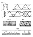
- Fig. l is a perspective view of a lattice girder comprising three longitudinal wires l which are interconnected by means of zigzag wire stirrups 2 to form a lattice girder having a triangular section.
- the wire stirrups 2 extend slightly beyond the respective longitudinal wire l, such that loops 3 are formed outside said wire.
- the loops 3 are cut open adjacent to the longitudinal wire l so as to form a groove 4 into which a transverse wire 5 can be inserted.
- a transverse wire 5 can be inserted.
- the loops 3 of neighbouring stirrups can be cut open in parallel with each other or, as shown to the right, they can be oppositely cut open so that the transverse wire 5 can be inserted into the grooves 4 by being turned.
- the wire 5 may be a single wire interconnecting several lattice girders, or it can be a wire in a mesh reinforcement or some other prefabricated reinforcement unit.
- Fig. 2 shows alternative embodiments of the lattice girder which may thus comprise two or four longitudinal wires l and a zigzag wire stirrup 2 extending on one side of the longitudinal wires l, or between pairs of longitudinal wires, as shown in the upper part of Fig. 2, viz. to the left a cross-section of the lattice girder and to the right a side view thereof.
- the lower part of Fig. 2 illustrates a further variant of the lattice girder with two longitudinal wires l and wire stirrups 2 extending on both sides thereof, as shown to the left.
- the wire stirrup 2 can be arranged in parallel with each other, as shown in the lower center part of the Figure, or can be relatively offset, as shown in the lower right part of the Figure.
- Figs. 3-5 show how a lattice girder according to one of the embodiments above can be used for reinforcing a structural member of concrete.
- the lattice girders exemplified above can, of course, be modified in different ways.
- the wire stirrups may be extended to form loops merely on one side of the lattice girder.
- the invention is therefore not limited to the embodiments described above and shown in the drawing, but can be modified within the scope of the appended claims.
Landscapes
- Engineering & Computer Science (AREA)
- Architecture (AREA)
- Civil Engineering (AREA)
- Structural Engineering (AREA)
- Reinforcement Elements For Buildings (AREA)
- Rod-Shaped Construction Members (AREA)
- Load-Engaging Elements For Cranes (AREA)
- Laser Surgery Devices (AREA)
- Surgical Instruments (AREA)
- Luminescent Compositions (AREA)
- Impact Printers (AREA)
- Seeds, Soups, And Other Foods (AREA)
- Medicines Containing Plant Substances (AREA)
Claims (4)
- Gitterträger zum Armieren von Verbundplatten oder ähnlichen Strukturen aus Beton mit longitudinalen Drähten (1), die sich parallel auf verschiedenen Ebenen erstrecken, und mit zickzackförmigen Bügeln (2), die die longitudinalen Drähte verbinden, dadurch gekennzeichnet, daß die Drahtbügel (2) sich auf wenigstens einer Seite über den jeweiligen longitudinalen Draht (1) hinaus erstrecken, so daß sie Schleifen (3) außerhalb des Drahtes bilden, und daß wenigstens einige dieser Schleifen (3) neben dem longitudinalen Draht (1) aufgeschnitten sind, um Vertiefungen (4) zu bilden, in die transversale Drähte (5) einsetzbar sind, um den Gitterträger mit anderen Armierungseinheiten zu verbinden.
- Gitterträger nach Anspruch 1, mit zwei parallelen Bügeln (2), die sich jeweils auf einer Seite der horizontalen Drähte (1) erstrecken, dadurch gekennzeichnet, daß die Schleifen (3) der Drahtbügel parallel zueinander aufgeschnitten sind, so daß die longitudinalen Drähte (5) in die Vertiefungen (4) von einer Seite aus einsetzbar sind.
- Gitterträger nach Anspruch 1, mit zwei parallelen Bügeln (2), die sich jeweils auf einer Seite der horizontalen Drähte (1) erstrecken, dadurch gekennzeichnet, daß die Schleifen (3) der Drahtbügel einander gegenüber aufgeschnitten sind, so daß die longitudinalen Drähte (5) in die Vertiefungen (4) einsetzbar sind, indem sie gedreht werden.
- Gitterträger nach einem der vorhergehenden Ansprüche, dadurch gekennzeichnet, daß die Drahtbügel (2) Schleifen (3) auf beiden Seiten des Gitterträgers bilden.
Priority Applications (1)
| Application Number | Priority Date | Filing Date | Title |
|---|---|---|---|
| AT88906205T ATE80436T1 (de) | 1987-07-03 | 1988-07-01 | Gittertraeger. |
Applications Claiming Priority (2)
| Application Number | Priority Date | Filing Date | Title |
|---|---|---|---|
| SE8702756 | 1987-07-03 | ||
| SE8702756A SE461538B (sv) | 1987-07-03 | 1987-07-03 | Gallerbalk |
Publications (2)
| Publication Number | Publication Date |
|---|---|
| EP0371983A1 EP0371983A1 (de) | 1990-06-13 |
| EP0371983B1 true EP0371983B1 (de) | 1992-09-09 |
Family
ID=20369057
Family Applications (1)
| Application Number | Title | Priority Date | Filing Date |
|---|---|---|---|
| EP88906205A Expired EP0371983B1 (de) | 1987-07-03 | 1988-07-01 | Gitterträger |
Country Status (8)
| Country | Link |
|---|---|
| EP (1) | EP0371983B1 (de) |
| AT (1) | ATE80436T1 (de) |
| DE (1) | DE3874539T2 (de) |
| DK (1) | DK164960C (de) |
| FI (1) | FI900008L (de) |
| NO (1) | NO172505C (de) |
| SE (1) | SE461538B (de) |
| WO (1) | WO1989000226A1 (de) |
Families Citing this family (7)
| Publication number | Priority date | Publication date | Assignee | Title |
|---|---|---|---|---|
| BE1009977A3 (nl) * | 1996-01-26 | 1997-11-04 | Paesen Rudi | Afstandhouder voor bewapening van wanden, vloeren, betonconstructies en dergelijke. |
| DE19949419C2 (de) * | 1998-10-13 | 2003-05-08 | Georg Weidner | Gitterträger oder Transport- und Verlegeanker für Hohl- und Filigranwände |
| DE19933101C1 (de) * | 1999-07-15 | 2001-05-23 | Hvg Haas Vertriebsgesellschaft | Tragsystem aus Gitterträger und Profilholz |
| DE29912526U1 (de) | 1999-07-19 | 1999-09-23 | Filigran Trägersysteme GmbH & Co KG, 31633 Leese | Durchstanzbewehrung für Flachdecken |
| DE10020572C2 (de) * | 2000-04-27 | 2002-04-11 | Rudolf Seiz | Gitterträgerausbaurahmen für den Berg- und Tunnelbau |
| RU2190068C2 (ru) * | 2000-09-08 | 2002-09-27 | Чернов Алексей Николаевич | Арматурный каркас |
| CN107217791B (zh) * | 2017-07-31 | 2023-06-20 | 广西路桥工程集团有限公司 | 一种轻型高强度的钢筋混凝土弓形结构梁 |
Family Cites Families (5)
| Publication number | Priority date | Publication date | Assignee | Title |
|---|---|---|---|---|
| DE200025C (de) * | ||||
| US1740493A (en) * | 1928-08-02 | 1929-12-24 | Charles R Birdsey | Plaster-board-joint reenforcement |
| DE1269324B (de) * | 1962-06-09 | 1968-05-30 | Walter Haslinger | Raeumlicher Fachwerktraeger |
| AT293697B (de) * | 1969-01-10 | 1971-10-25 | Franz Filzmoser | Gitterträger |
| FR2065639A1 (de) * | 1969-09-01 | 1971-08-06 | Davum |
-
1987
- 1987-07-03 SE SE8702756A patent/SE461538B/sv not_active IP Right Cessation
-
1988
- 1988-07-01 AT AT88906205T patent/ATE80436T1/de not_active IP Right Cessation
- 1988-07-01 FI FI900008A patent/FI900008L/fi not_active Application Discontinuation
- 1988-07-01 WO PCT/SE1988/000366 patent/WO1989000226A1/en not_active Ceased
- 1988-07-01 EP EP88906205A patent/EP0371983B1/de not_active Expired
- 1988-07-01 DE DE8888906205T patent/DE3874539T2/de not_active Revoked
-
1989
- 1989-12-21 NO NO895164A patent/NO172505C/no unknown
- 1989-12-29 DK DK672189A patent/DK164960C/da not_active IP Right Cessation
Also Published As
| Publication number | Publication date |
|---|---|
| DE3874539T2 (de) | 1993-02-04 |
| WO1989000226A1 (en) | 1989-01-12 |
| NO895164D0 (no) | 1989-12-21 |
| DE3874539D1 (de) | 1992-10-15 |
| ATE80436T1 (de) | 1992-09-15 |
| NO895164L (no) | 1990-01-03 |
| NO172505C (no) | 1993-07-28 |
| DK164960C (da) | 1993-02-15 |
| EP0371983A1 (de) | 1990-06-13 |
| DK672189A (da) | 1989-12-29 |
| SE8702756D0 (sv) | 1987-07-03 |
| SE461538B (sv) | 1990-02-26 |
| NO172505B (no) | 1993-04-19 |
| FI900008A7 (fi) | 1990-01-02 |
| DK672189D0 (da) | 1989-12-29 |
| FI900008A0 (fi) | 1990-01-02 |
| FI900008L (fi) | 1990-01-02 |
| DK164960B (da) | 1992-09-21 |
| SE8702756L (sv) | 1989-01-04 |
Similar Documents
| Publication | Publication Date | Title |
|---|---|---|
| DE69802193T2 (de) | Säule aus verbundstahl-beton | |
| US3885369A (en) | Structural element | |
| PL246530B1 (pl) | Węzeł połączeniowy dwuteowników | |
| US5560176A (en) | Prefabricated steel-concrete composite beam | |
| EP1664453A4 (de) | Anvick-öffnungsvorrichtung und verfahren zur herstellung und verwendung derselben | |
| SE416417B (sv) | Fackverksbalk for stalbetongkonstruktioner | |
| WO1989000226A1 (en) | Lattice girder | |
| GB2251018A (en) | Chord member for lattice panel bridge | |
| US3303627A (en) | Reinforced structural members | |
| CA1100713A (en) | Unit construction steel bridges | |
| US9487954B2 (en) | Laced composite system | |
| WO1994019560A1 (en) | Prefabricated steel-concrete composite beam | |
| DE60007824T2 (de) | Gitterträger | |
| DE579814C (de) | Eisenbetonbalkendecke aus aneinandergereihten, fertigen, trogfoermigen Eisenbetonbalken | |
| DE268466C (de) | ||
| JPS59209818A (ja) | 鉄筋コンクリ−ト製部材の配筋構造 | |
| CH358574A (de) | Bauelement | |
| DE950883C (de) | Skelettbau | |
| JPH11141050A (ja) | 鉄筋トラスの構造及び鉄筋コンクリート構造物 | |
| EP3026199B1 (de) | Hohlwandanker | |
| CN121853678A (zh) | 一种装配式混凝土结构强抗震结构体系 | |
| JPH0358417B2 (de) | ||
| EP0484345B1 (de) | Verbesserungen an kompositbalken | |
| US805137A (en) | Ceiling. | |
| DE3222454A1 (de) | Stahlbetontraeger mit im untergurtbereich einbetonierter ankerschiene |
Legal Events
| Date | Code | Title | Description |
|---|---|---|---|
| PUAI | Public reference made under article 153(3) epc to a published international application that has entered the european phase |
Free format text: ORIGINAL CODE: 0009012 |
|
| 17P | Request for examination filed |
Effective date: 19891218 |
|
| AK | Designated contracting states |
Kind code of ref document: A1 Designated state(s): AT BE CH DE FR GB IT LI LU NL SE |
|
| RAP1 | Party data changed (applicant data changed or rights of an application transferred) |
Owner name: FUNDIA BYGG AB |
|
| 17Q | First examination report despatched |
Effective date: 19910902 |
|
| GRAA | (expected) grant |
Free format text: ORIGINAL CODE: 0009210 |
|
| AK | Designated contracting states |
Kind code of ref document: B1 Designated state(s): AT BE CH DE FR GB IT LI LU NL SE |
|
| PG25 | Lapsed in a contracting state [announced via postgrant information from national office to epo] |
Ref country code: NL Effective date: 19920909 Ref country code: IT Free format text: LAPSE BECAUSE OF FAILURE TO SUBMIT A TRANSLATION OF THE DESCRIPTION OR TO PAY THE FEE WITHIN THE PRESCRIBED TIME-LIMIT;WARNING: LAPSES OF ITALIAN PATENTS WITH EFFECTIVE DATE BEFORE 2007 MAY HAVE OCCURRED AT ANY TIME BEFORE 2007. THE CORRECT EFFECTIVE DATE MAY BE DIFFERENT FROM THE ONE RECORDED. Effective date: 19920909 Ref country code: SE Effective date: 19920909 Ref country code: AT Effective date: 19920909 |
|
| REF | Corresponds to: |
Ref document number: 80436 Country of ref document: AT Date of ref document: 19920915 Kind code of ref document: T |
|
| REF | Corresponds to: |
Ref document number: 3874539 Country of ref document: DE Date of ref document: 19921015 |
|
| PG25 | Lapsed in a contracting state [announced via postgrant information from national office to epo] |
Ref country code: LU Free format text: LAPSE BECAUSE OF REVOCATION BY EPO Effective date: 19921031 |
|
| REG | Reference to a national code |
Ref country code: CH Ref legal event code: PL |
|
| ET | Fr: translation filed | ||
| NLV1 | Nl: lapsed or annulled due to failure to fulfill the requirements of art. 29p and 29m of the patents act | ||
| PLBI | Opposition filed |
Free format text: ORIGINAL CODE: 0009260 |
|
| PG25 | Lapsed in a contracting state [announced via postgrant information from national office to epo] |
Ref country code: GB Effective date: 19930701 |
|
| 26 | Opposition filed |
Opponent name: BADISCHE DRAHTWERKE GMBH Effective date: 19930511 |
|
| PG25 | Lapsed in a contracting state [announced via postgrant information from national office to epo] |
Ref country code: CH Free format text: LAPSE BECAUSE OF NON-PAYMENT OF DUE FEES Effective date: 19930731 Ref country code: BE Effective date: 19930731 Ref country code: LI Free format text: LAPSE BECAUSE OF NON-PAYMENT OF DUE FEES Effective date: 19930731 |
|
| BERE | Be: lapsed |
Owner name: FUNDIA BYGG A.B. Effective date: 19930731 |
|
| GBPC | Gb: european patent ceased through non-payment of renewal fee |
Effective date: 19930701 |
|
| REG | Reference to a national code |
Ref country code: FR Ref legal event code: ST |
|
| RDAC | Information related to revocation of patent modified |
Free format text: ORIGINAL CODE: 0009299REVO |
|
| RDAG | Patent revoked |
Free format text: ORIGINAL CODE: 0009271 |
|
| STAA | Information on the status of an ep patent application or granted ep patent |
Free format text: STATUS: PATENT REVOKED |
|
| 27W | Patent revoked |
Effective date: 19940328 |
|
| R27W | Patent revoked (corrected) |
Effective date: 19940328 |
|
| REG | Reference to a national code |
Ref country code: CH Ref legal event code: PL |