EP0372003B1 - Chicanes pour colonnes d'echange de chaleur et de matieres - Google Patents
Chicanes pour colonnes d'echange de chaleur et de matieres Download PDFInfo
- Publication number
- EP0372003B1 EP0372003B1 EP88909312A EP88909312A EP0372003B1 EP 0372003 B1 EP0372003 B1 EP 0372003B1 EP 88909312 A EP88909312 A EP 88909312A EP 88909312 A EP88909312 A EP 88909312A EP 0372003 B1 EP0372003 B1 EP 0372003B1
- Authority
- EP
- European Patent Office
- Prior art keywords
- basic
- basic elements
- packing element
- layer
- adjacent
- Prior art date
- Legal status (The legal status is an assumption and is not a legal conclusion. Google has not performed a legal analysis and makes no representation as to the accuracy of the status listed.)
- Expired - Lifetime
Links
- 210000001520 comb Anatomy 0.000 claims description 8
- 238000012856 packing Methods 0.000 claims 14
- 239000007788 liquid Substances 0.000 description 10
- 230000018109 developmental process Effects 0.000 description 9
- 238000009434 installation Methods 0.000 description 3
- 230000012447 hatching Effects 0.000 description 2
- 238000004519 manufacturing process Methods 0.000 description 2
- 239000002184 metal Substances 0.000 description 2
- 238000009827 uniform distribution Methods 0.000 description 2
- 238000004804 winding Methods 0.000 description 2
- 238000010521 absorption reaction Methods 0.000 description 1
- 230000001174 ascending effect Effects 0.000 description 1
- 238000009826 distribution Methods 0.000 description 1
- 239000004744 fabric Substances 0.000 description 1
- 230000002349 favourable effect Effects 0.000 description 1
- 230000000630 rising effect Effects 0.000 description 1
Images


Classifications
-
- F—MECHANICAL ENGINEERING; LIGHTING; HEATING; WEAPONS; BLASTING
- F28—HEAT EXCHANGE IN GENERAL
- F28F—DETAILS OF HEAT-EXCHANGE AND HEAT-TRANSFER APPARATUS, OF GENERAL APPLICATION
- F28F25/00—Component parts of trickle coolers
-
- B—PERFORMING OPERATIONS; TRANSPORTING
- B01—PHYSICAL OR CHEMICAL PROCESSES OR APPARATUS IN GENERAL
- B01J—CHEMICAL OR PHYSICAL PROCESSES, e.g. CATALYSIS OR COLLOID CHEMISTRY; THEIR RELEVANT APPARATUS
- B01J19/00—Chemical, physical or physico-chemical processes in general; Their relevant apparatus
- B01J19/32—Packing elements in the form of grids or built-up elements for forming a unit or module inside the apparatus for mass or heat transfer
-
- B—PERFORMING OPERATIONS; TRANSPORTING
- B01—PHYSICAL OR CHEMICAL PROCESSES OR APPARATUS IN GENERAL
- B01J—CHEMICAL OR PHYSICAL PROCESSES, e.g. CATALYSIS OR COLLOID CHEMISTRY; THEIR RELEVANT APPARATUS
- B01J2219/00—Chemical, physical or physico-chemical processes in general; Their relevant apparatus
- B01J2219/32—Details relating to packing elements in the form of grids or built-up elements for forming a unit of module inside the apparatus for mass or heat transfer
- B01J2219/322—Basic shape of the elements
- B01J2219/32203—Sheets
- B01J2219/32206—Flat sheets
-
- B—PERFORMING OPERATIONS; TRANSPORTING
- B01—PHYSICAL OR CHEMICAL PROCESSES OR APPARATUS IN GENERAL
- B01J—CHEMICAL OR PHYSICAL PROCESSES, e.g. CATALYSIS OR COLLOID CHEMISTRY; THEIR RELEVANT APPARATUS
- B01J2219/00—Chemical, physical or physico-chemical processes in general; Their relevant apparatus
- B01J2219/32—Details relating to packing elements in the form of grids or built-up elements for forming a unit of module inside the apparatus for mass or heat transfer
- B01J2219/322—Basic shape of the elements
- B01J2219/32203—Sheets
- B01J2219/3221—Corrugated sheets
-
- B—PERFORMING OPERATIONS; TRANSPORTING
- B01—PHYSICAL OR CHEMICAL PROCESSES OR APPARATUS IN GENERAL
- B01J—CHEMICAL OR PHYSICAL PROCESSES, e.g. CATALYSIS OR COLLOID CHEMISTRY; THEIR RELEVANT APPARATUS
- B01J2219/00—Chemical, physical or physico-chemical processes in general; Their relevant apparatus
- B01J2219/32—Details relating to packing elements in the form of grids or built-up elements for forming a unit of module inside the apparatus for mass or heat transfer
- B01J2219/322—Basic shape of the elements
- B01J2219/32203—Sheets
- B01J2219/32224—Sheets characterised by the orientation of the sheet
- B01J2219/32227—Vertical orientation
-
- B—PERFORMING OPERATIONS; TRANSPORTING
- B01—PHYSICAL OR CHEMICAL PROCESSES OR APPARATUS IN GENERAL
- B01J—CHEMICAL OR PHYSICAL PROCESSES, e.g. CATALYSIS OR COLLOID CHEMISTRY; THEIR RELEVANT APPARATUS
- B01J2219/00—Chemical, physical or physico-chemical processes in general; Their relevant apparatus
- B01J2219/32—Details relating to packing elements in the form of grids or built-up elements for forming a unit of module inside the apparatus for mass or heat transfer
- B01J2219/322—Basic shape of the elements
- B01J2219/32203—Sheets
- B01J2219/32248—Sheets comprising areas that are raised or sunken from the plane of the sheet
-
- B—PERFORMING OPERATIONS; TRANSPORTING
- B01—PHYSICAL OR CHEMICAL PROCESSES OR APPARATUS IN GENERAL
- B01J—CHEMICAL OR PHYSICAL PROCESSES, e.g. CATALYSIS OR COLLOID CHEMISTRY; THEIR RELEVANT APPARATUS
- B01J2219/00—Chemical, physical or physico-chemical processes in general; Their relevant apparatus
- B01J2219/32—Details relating to packing elements in the form of grids or built-up elements for forming a unit of module inside the apparatus for mass or heat transfer
- B01J2219/322—Basic shape of the elements
- B01J2219/32203—Sheets
- B01J2219/32255—Other details of the sheets
-
- B—PERFORMING OPERATIONS; TRANSPORTING
- B01—PHYSICAL OR CHEMICAL PROCESSES OR APPARATUS IN GENERAL
- B01J—CHEMICAL OR PHYSICAL PROCESSES, e.g. CATALYSIS OR COLLOID CHEMISTRY; THEIR RELEVANT APPARATUS
- B01J2219/00—Chemical, physical or physico-chemical processes in general; Their relevant apparatus
- B01J2219/32—Details relating to packing elements in the form of grids or built-up elements for forming a unit of module inside the apparatus for mass or heat transfer
- B01J2219/324—Composition or microstructure of the elements
- B01J2219/32408—Metal
Definitions
- the invention relates to a built-in element for a mass and heat exchange column with at least one zigzag-shaped layer of adjacent and inclined in two preferred directions guide surfaces, in which the layer is composed of basic elements which extend above and below the median plane of the layer.
- a known built-in element (EP-A-72 875) consists of several layers, each layer being a zigzag-shaped, continuous structure and having mutually adjacent and interconnected rows of guide surfaces. Each The second guide surface of a row of guide surfaces protrudes from the flank planes of the prongs.
- the layers of such a built-in element must have large wall thicknesses in order to ensure sufficient stability.
- large wall thicknesses increase the manufacturing costs and the weight and reduce the column cross-section available for the mass and heat exchange.
- the invention is therefore based on the object of developing a built-in element of the type mentioned which, with high stability, ensures a uniform distribution of the flowing liquid and the rising gas over the column cross section and which is inexpensively manufactured.
- each basic element is connected to three adjacent basic elements, one of which has the same preferred direction as the basic element, the other two have the other preferred direction, and that the basic elements which are in the direction of the ridge of the zigzag Arrangements lie side by side, each have different preferred directions.
- the installation element according to the invention has basic elements which form or have projecting roofs or gaps with at least one free edge and allow the liquid to drip off onto an adjacent basic element, on which the liquid receives a different direction.
- the arrangement causes the flowing liquid flow to split into partial flows which divide from basic element to basic element, partially mix again and change their flow direction. In this way, the liquid is distributed evenly over the column cross-section and the uniform distribution achieved is maintained even over large flow paths.
- the basic elements which are staggered from row to row, create an open structure with low flow resistance. Due to the uniform liquid distribution, the installation elements can have large installation heights.
- the basic elements are inclined between 30 and 60 °, preferably approximately 45 °, with respect to the central plane of the layer.
- the position is arranged parallel to the axis of the column and the ridges of the zigzag arrangement are inclined between 30 and 90 ° with respect to the axis.
- a particularly favorable type of manufacture results if, according to a development of the subject matter of the invention, the layer is wound spirally.
- the layer is preferably made from a corresponding punched and folded band, in particular sheet metal band.
- the tape is wound on a winding axis, which preferably coincides with the column axis.
- each basic element is surrounded by six neighboring basic elements.
- each basic element is surrounded by five neighboring basic elements.
- At least some of the basic elements advantageously have a roof projecting from their surface.
- the roof extends over the entire surface of a basic element.
- the roof points in one of the two preferred directions.
- the roof has a rectangular base.
- a number of basic elements with roofs and a number of basic elements without roofs are alternately provided perpendicular to the course of the ridge.
- the roof extends over more than half the length of a basic element.
- the roof extends over less than half the length of a basic element and is arranged asymmetrically on the basic element.
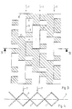
- the layer according to FIG. 1 is formed by a zigzag-shaped strip, which is preferably made of sheet metal.
- the location is made up of a large number of rectangular basic elements 1 of the same size, which are in two preferred directions are inclined.
- the basic element 1 is highlighted by a dashed outline.
- the basic elements 1 inclined in one preferred direction are hatched, the basic elements inclined in the other preferred directions are shown without hatching.
- the zigzag-shaped layer has combs, the position of which is indicated by arrows 2.
- the layer has incisions 3 at regular intervals along the ridges. From the two ends of the incisions 3 and at right angles thereto, a further incision 4, 5 leads perpendicular to the ridge course to the middle between two adjacent ridges.
- Each basic element 1 is connected to three adjacent basic elements 6, 7, 8. With one of the adjacent basic elements 7, the basic element 1 is connected between two incisions 3 over the course of the comb.
- the base element 1 On its opposite side, the base element 1 is connected to the adjacent base elements 6, 8, the base element 6 having the same preferred direction as the base element 1, while the base element 8, like the base element 7, points in the other direction.
- Those basic elements which, viewed in the direction of the ridge course, lie next to the basic element 1 each have a different preferred direction than this.
- roofs Two cut edges each on an outer corner of a basic element delimit projections, which are referred to below as roofs.
- the basic elements 30, 40 and 41 in FIG. 1 are listed as examples of this: in the case of the hatched element 30, these are the cut edges 3 and 5.
- a roof on the element 40 is delimited by the cut edges 3 and 4, one on the element 41 by the edges 3 and 5.
- a built-in element composed of one or more layers of the type described is installed in a heat or mass transfer column such that an angle between 30 and 90 °, preferably 30 to 60 °, is included between the column axis and the direction of the ridge course.
- the projecting roofs allow the liquid running down in the column to drip from one layer to an adjacent layer, i.e. a liquid transport across the layer.
- the preferred direction of the basic elements is in each case inclined at approximately 45 ° with respect to the central plane 9.
- the body edges of the basic elements lying behind the section plane are shown in dashed lines for the sake of clarity.
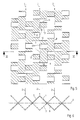
- Figure 3 shows a further embodiment of a layer.
- the zigzag-shaped structure with the comb shape marked by the arrows 2 has cuts 10 transversely to the comb shape, the length of which corresponds to the distance between two adjacent combs and which extend symmetrically to the left and right of each comb.
- the distance between two adjacent incisions 10 corresponds to the length of a basic element.
- the incisions 10 transverse to adjacent combs are offset from one another by half the length of a basic element.
- the width of a basic element 1 corresponds to half the length of an incision 10.
- Each basic element extends between the ridge and the central plane 9 of the layer.
- Each basic element 1 is connected to three adjacent basic elements 6, 7, 8.
- the basic elements are inclined in two preferred directions, the basic elements pointing in one preferred direction being hatched, the basic elements pointing in the other preferred direction being shown without hatching.
- One of the basic elements 7 adjacent to the basic element 1 is arranged next to this on the other side of the comb and has the other preferred direction than the basic element 1.
- the two other basic elements 6, 8 connected to the basic element 1 are each offset by half a length of a basic element with respect to the basic element 1.
- One of the neighboring basic elements 6 has the same preferred direction as the basic element 1, the other neighboring basic element 8 has the other preferred direction.
- each basic element in every other row of basic elements, i.e. Basic elements, which are seen next to each other in the direction of the ridge course, each basic element (in the figure these include the basic elements 7, 6, 8) with three incisions 11, 12, 13.
- the incision 12 extends along the course of the ridge over part of the longitudinal edge of the basic element, the two incisions 11, 13 each extend from one end of the incision 12 perpendicularly to it over the entire width of the basic element.
- the partial area of the base element delimited by the incisions 11, 12, 13 is bent out of the preferred direction which the base element has and preferably inclined in the other of the two preferred directions.
- the two preferred directions are advantageously inclined at 45 ° to the central plane 9 of the position.
- the layer is arranged in a column in such a way that an angle between 30 and 90 ° is formed between the ridges and the column axis.
- FIGS. 5 and 6 show an embodiment of a layer in which basic elements are arranged in the same way as in the layer according to FIG. 3.
- the incisions 11, 12, 13 are not arranged symmetrically to the center line of the base element, and the cut 12 extends over less than half the length of the base element.
- the cuts 11, 12, 13 are arranged in each of the basic elements, and not only in every basic element of every second row of basic elements.
- the incisions 12 are provided along the combs of the layer, namely two cuts 12 spaced from one another are provided between two incisions 10.
- each incision 12 From the two ends of each incision 12 lead at right angles in the same direction incisions 11, 13 which extend to the middle between two adjacent ridges.
- the incisions 11, 12, 13 delimit a partial surface of a basic element which is bent out of the plane defined by the basic element along the line which extends between the two free ends of the cuts 11, 13.
- the partial surfaces are preferably inclined in the other of the two preferred directions as the basic element.
- the layers described with reference to FIGS. 1 to 6 can be used both individually and in combination with other layers as built-in elements for fabric and heat exchange columns. For example, several layers can be parallel to be sandwiched one on top of the other to be joined together to form a built-in element. Layers of the same type or combinations of layers of different types can be formed. The layers can be joined together in such a way that their ridges are directed parallel to one another, or that the ridges of individual layers or individual groups of layers point in different directions. As a boundary condition it should be noted that an angle between 30 and 90 ° is formed between the direction of the ridges and the column axis. If necessary, the layers can be provided with a corrugated surface instead of a smooth surface.
- a layer of sufficient length is spirally wound and the built-in element 14 formed in this way is inserted into a column, the winding axis preferably coinciding with the column axis 16. It must also be taken into account here that the ridges form an angle between 30 and 90 ° with the column axis.
Landscapes
- Physics & Mathematics (AREA)
- Thermal Sciences (AREA)
- Engineering & Computer Science (AREA)
- Chemical & Material Sciences (AREA)
- Mechanical Engineering (AREA)
- General Engineering & Computer Science (AREA)
- Organic Chemistry (AREA)
- Chemical Kinetics & Catalysis (AREA)
- Heat-Exchange Devices With Radiators And Conduit Assemblies (AREA)
Abstract
Claims (14)
Applications Claiming Priority (2)
| Application Number | Priority Date | Filing Date | Title |
|---|---|---|---|
| DE19873735923 DE3735923A1 (de) | 1987-10-23 | 1987-10-23 | Einbauelement fuer eine stoff- und waermeaustauschkolonne |
| DE3735923 | 1987-10-23 |
Publications (2)
| Publication Number | Publication Date |
|---|---|
| EP0372003A1 EP0372003A1 (fr) | 1990-06-13 |
| EP0372003B1 true EP0372003B1 (fr) | 1991-06-26 |
Family
ID=6338949
Family Applications (1)
| Application Number | Title | Priority Date | Filing Date |
|---|---|---|---|
| EP88909312A Expired - Lifetime EP0372003B1 (fr) | 1987-10-23 | 1988-10-19 | Chicanes pour colonnes d'echange de chaleur et de matieres |
Country Status (4)
| Country | Link |
|---|---|
| EP (1) | EP0372003B1 (fr) |
| AU (1) | AU2608488A (fr) |
| DE (2) | DE3735923A1 (fr) |
| WO (1) | WO1989003719A1 (fr) |
Family Cites Families (3)
| Publication number | Priority date | Publication date | Assignee | Title |
|---|---|---|---|---|
| EP0070915A1 (fr) * | 1981-07-30 | 1983-02-09 | GebràDer Sulzer Aktiengesellschaft | Elément incorporé pour un dispositif d'échange de matières et d'échange direct de chaleur et pour un dispositif mélangeur |
| CH653909A5 (de) * | 1981-07-30 | 1986-01-31 | Sulzer Ag | Kolonne fuer stoff- und/oder waermeaustauschverfahren. |
| CH653565A5 (de) * | 1981-07-30 | 1986-01-15 | Sulzer Ag | Vorrichtung zum stoff- und/oder direkten waermeaustausch oder mischen. |
-
1987
- 1987-10-23 DE DE19873735923 patent/DE3735923A1/de not_active Withdrawn
-
1988
- 1988-10-19 EP EP88909312A patent/EP0372003B1/fr not_active Expired - Lifetime
- 1988-10-19 WO PCT/EP1988/000939 patent/WO1989003719A1/fr not_active Ceased
- 1988-10-19 DE DE8888909312T patent/DE3863427D1/de not_active Expired - Fee Related
- 1988-10-19 AU AU26084/88A patent/AU2608488A/en not_active Abandoned
Also Published As
| Publication number | Publication date |
|---|---|
| AU2608488A (en) | 1989-05-23 |
| DE3863427D1 (de) | 1991-08-01 |
| EP0372003A1 (fr) | 1990-06-13 |
| WO1989003719A1 (fr) | 1989-05-05 |
| DE3735923A1 (de) | 1989-06-01 |
Similar Documents
| Publication | Publication Date | Title |
|---|---|---|
| EP0069241B1 (fr) | Garniture pour colonnes d'échange de matières et procédé de fabrication de la garniture | |
| EP0072875B1 (fr) | Elément incorporé pour un dispositif d'échange de matières et d'échange direct de chaleur et pour un dispositif mélangeur | |
| DE2733640C3 (de) | Matrix für einen katalytischen Reaktor zur Abgasreinigung bei Brennkraftmaschinen | |
| DE2601890C3 (de) | Packungskörper für Stoffaustauschkolonnen | |
| DE1269144B (de) | Plattenwaermetauscher | |
| EP0321480B1 (fr) | Echangeur de chaleur du type a plaques | |
| DE1544027B2 (de) | Einbauten für eine Dampf-Flüssigkeitskontakteinrichtung | |
| EP0152560B1 (fr) | Matrice pour réacteur catalytique pour purifier des gaz d'échappement | |
| EP0151693A2 (fr) | Colonne d'échange de matière | |
| DE69314410T2 (de) | Gitterpackungselement für Gas-Flüssig-Kontaktapparate | |
| EP0761303B1 (fr) | Elément de garnissage pour colonnes d'échange de matière ou de chaleur | |
| DE2945103A1 (de) | Fluessigkeitsverteiler fuer eine gegenstromkolonne | |
| EP0361225A1 (fr) | Elément de remplissage | |
| EP1540662B1 (fr) | Distanceur | |
| DE1751538A1 (de) | Brenner fuer fluessige und gasfoermige Brennstoffe | |
| EP0372003B1 (fr) | Chicanes pour colonnes d'echange de chaleur et de matieres | |
| EP0565750B1 (fr) | Elément de fermeture mécanique et liaison obtenue avec cet élément | |
| DE3409524C1 (de) | Flüssigkeitsverteiler für eine Gegenstromkolonne | |
| DE2534445A1 (de) | Gegenstromwaermeaustauscher | |
| DE3844350A1 (de) | Traegerkoerper fuer einen katalytischen reaktor zur abgasreinigung | |
| EP0389750A1 (fr) | Support pour un réacteur catalytique de purification des gaz d'échappement | |
| DE2910525C2 (de) | Austauschkolonnenpackung | |
| DE2350601C2 (de) | Rieseleinbau für Kühltürme | |
| EP4495532B1 (fr) | Treillis ondulé | |
| DE19537690C2 (de) | Einbauelement für Stoff- oder Wärmeaustauschkolonnen |
Legal Events
| Date | Code | Title | Description |
|---|---|---|---|
| PUAI | Public reference made under article 153(3) epc to a published international application that has entered the european phase |
Free format text: ORIGINAL CODE: 0009012 |
|
| 17P | Request for examination filed |
Effective date: 19900328 |
|
| AK | Designated contracting states |
Kind code of ref document: A1 Designated state(s): BE CH DE FR GB IT LI NL SE |
|
| 17Q | First examination report despatched |
Effective date: 19901123 |
|
| GRAA | (expected) grant |
Free format text: ORIGINAL CODE: 0009210 |
|
| AK | Designated contracting states |
Kind code of ref document: B1 Designated state(s): BE CH DE FR GB IT LI NL SE |
|
| PG25 | Lapsed in a contracting state [announced via postgrant information from national office to epo] |
Ref country code: IT Free format text: LAPSE BECAUSE OF FAILURE TO SUBMIT A TRANSLATION OF THE DESCRIPTION OR TO PAY THE FEE WITHIN THE PRE;WARNING: LAPSES OF ITALIAN PATENTS WITH EFFECTIVE DATE BEFORE 2007 MAY HAVE OCCURRED AT ANY TIME BEFORE 2007. THE CORRECT EFFECTIVE DATE MAY BE DIFFERENT FROM THE ONE RECORDED.SCRIBED TIME-LIMIT Effective date: 19910626 Ref country code: SE Effective date: 19910626 Ref country code: NL Effective date: 19910626 Ref country code: FR Effective date: 19910626 Ref country code: BE Effective date: 19910626 Ref country code: GB Effective date: 19910626 |
|
| REF | Corresponds to: |
Ref document number: 3863427 Country of ref document: DE Date of ref document: 19910801 |
|
| PG25 | Lapsed in a contracting state [announced via postgrant information from national office to epo] |
Ref country code: LI Effective date: 19911031 Ref country code: CH Effective date: 19911031 |
|
| EN | Fr: translation not filed | ||
| NLV1 | Nl: lapsed or annulled due to failure to fulfill the requirements of art. 29p and 29m of the patents act | ||
| GBV | Gb: ep patent (uk) treated as always having been void in accordance with gb section 77(7)/1977 [no translation filed] | ||
| PLBE | No opposition filed within time limit |
Free format text: ORIGINAL CODE: 0009261 |
|
| STAA | Information on the status of an ep patent application or granted ep patent |
Free format text: STATUS: NO OPPOSITION FILED WITHIN TIME LIMIT |
|
| 26N | No opposition filed | ||
| REG | Reference to a national code |
Ref country code: CH Ref legal event code: PL |
|
| PGFP | Annual fee paid to national office [announced via postgrant information from national office to epo] |
Ref country code: DE Payment date: 19940309 Year of fee payment: 6 |
|
| PG25 | Lapsed in a contracting state [announced via postgrant information from national office to epo] |
Ref country code: DE Effective date: 19950701 |