EP0372102A1 - Procédé de commande de l'angle d'allumage pour un moteur à combustion - Google Patents
Procédé de commande de l'angle d'allumage pour un moteur à combustion Download PDFInfo
- Publication number
- EP0372102A1 EP0372102A1 EP88120180A EP88120180A EP0372102A1 EP 0372102 A1 EP0372102 A1 EP 0372102A1 EP 88120180 A EP88120180 A EP 88120180A EP 88120180 A EP88120180 A EP 88120180A EP 0372102 A1 EP0372102 A1 EP 0372102A1
- Authority
- EP
- European Patent Office
- Prior art keywords
- values
- normal
- transition
- special
- ignition angle
- Prior art date
- Legal status (The legal status is an assumption and is not a legal conclusion. Google has not performed a legal analysis and makes no representation as to the accuracy of the status listed.)
- Granted
Links
Images

Classifications
-
- F—MECHANICAL ENGINEERING; LIGHTING; HEATING; WEAPONS; BLASTING
- F02—COMBUSTION ENGINES; HOT-GAS OR COMBUSTION-PRODUCT ENGINE PLANTS
- F02P—IGNITION, OTHER THAN COMPRESSION IGNITION, FOR INTERNAL-COMBUSTION ENGINES; TESTING OF IGNITION TIMING IN COMPRESSION-IGNITION ENGINES
- F02P5/00—Advancing or retarding ignition; Control therefor
- F02P5/04—Advancing or retarding ignition; Control therefor automatically, as a function of the working conditions of the engine or vehicle or of the atmospheric conditions
- F02P5/145—Advancing or retarding ignition; Control therefor automatically, as a function of the working conditions of the engine or vehicle or of the atmospheric conditions using electrical means
- F02P5/15—Digital data processing
- F02P5/1502—Digital data processing using one central computing unit
- F02P5/1504—Digital data processing using one central computing unit with particular means during a transient phase, e.g. acceleration, deceleration, gear change
-
- Y—GENERAL TAGGING OF NEW TECHNOLOGICAL DEVELOPMENTS; GENERAL TAGGING OF CROSS-SECTIONAL TECHNOLOGIES SPANNING OVER SEVERAL SECTIONS OF THE IPC; TECHNICAL SUBJECTS COVERED BY FORMER USPC CROSS-REFERENCE ART COLLECTIONS [XRACs] AND DIGESTS
- Y02—TECHNOLOGIES OR APPLICATIONS FOR MITIGATION OR ADAPTATION AGAINST CLIMATE CHANGE
- Y02T—CLIMATE CHANGE MITIGATION TECHNOLOGIES RELATED TO TRANSPORTATION
- Y02T10/00—Road transport of goods or passengers
- Y02T10/10—Internal combustion engine [ICE] based vehicles
- Y02T10/40—Engine management systems
Definitions
- the invention relates to a method for controlling the ignition angle of an internal combustion engine according to the preamble of claim 1.
- DE-PS 29 17 888 describes a method in which the ignition angle is delayed after the end of a special operation - overrun - and is then controlled back to the normal values for normal operation during a transition operation according to transition values. These transitional values are incrementally increased by a certain amount until the normal values are reached. The graphic course of these transition values follows a linear function.
- the object of the invention is to select the transition values so that there is always an optimal transition to the normal values.
- the solution according to the invention is based on the consideration that, based on a last special value, the transitional operation should always take the same length regardless of the size of the normal values, or should be completed after an equal number of cycles. This is achieved by adapting the transition values to the course of the normal values.
- the difference between normal value and transition value is reduced by a certain amount for each cycle.
- the number of cycles until this difference becomes zero is therefore always the same for a certain initial difference regardless of the size of the normal values. This number is determined by the amount by which the difference is reduced in each cycle.
- the torque is built up continuously, since the transition values for controlling the ignition angle are based on the normal values and are therefore independent of changes in the operating state of the internal combustion engine.
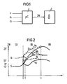
- 1 denotes a microcomputer, to which input signals are fed which correspond to the values for a speed n, an air quantity m and a throttle valve angle of an internal combustion engine. From this, the microcomputer 1 calculates normal values N for normal operation NB of the internal combustion engine, according to which it controls an ignition angle ZW. This is indicated in FIG. 1 via an operative connection to an ignition device 2.
- the microcomputer 1 controls the ignition angle ZW according to special values S.
- special values S are shifted relative to the normal values N in such a way that a later ignition angle ZW is controlled and a desired torque reduction during overrun results.
- the ignition angle ZW is controlled in accordance with transition values U which are selected such that the torque builds up again continuously, that is to say without jerking.
- ignition angle values are shown in a diagram using the example of overrun operation, with a subsequent transition and normal operation. Bars i are plotted on the abscissa and the associated ignition angle ZW is plotted on the ordinate. The clocks i are synchronized with the crankshaft e.g. generated for a six-cylinder machine every 120 °.
- the special operation SB-overrun is to be present up to the cycle labeled zero, followed by the transition mode UB, which ends at the cycle labeled x and finally normal operation NB.
- the normal values N, special values S and transition values U are not shown point by point, but rather as a curve.
- the solid curves are the values according to which the ignition angle ZW is controlled and the dashed curves show the associated normal values N.
- the ignition angle ZW is controlled according to the special values S during overrun operation.
- a typical range for these special values S is approximately 0 to -4 ° late ignition.
- the range of normal values N is approximately 15 ° to 25 ° early ignition.
- the ignition angle ZW controlled according to the special values S must be controlled back to the normal values N during the transition mode UB.
- the microcomputer 1 calculates an initial difference D0 from the normal value N0 and the special value S0 at cycle 0.
- transition values U are then determined from the respective normal values N minus the initial difference D0 reduced by a constant A for each cycle.
- the flow diagram according to FIG. 3 shows the exact calculation of these transition values U.
- the program run is started and the next step is to read in the special value S0, the normal value N0 at cycle 0 and the constant A.
- This constant A can be 1 ° or 2 °, for example.
- the initial difference D0 is calculated from N0 and S0 and then the clock cycle variable i is set to one for the calculation of the first transition value U1.
- a difference D1 is formed from the initial difference D0 and the constant A during this first program run.
- the transition value U1 can then be calculated in the next step from the difference between the normal value N1 and the difference D1.
- the ignition angle ZW is then controlled in accordance with this transition value U1.
Landscapes
- Engineering & Computer Science (AREA)
- Theoretical Computer Science (AREA)
- Signal Processing (AREA)
- Chemical & Material Sciences (AREA)
- Combustion & Propulsion (AREA)
- Mechanical Engineering (AREA)
- General Engineering & Computer Science (AREA)
- Electrical Control Of Ignition Timing (AREA)
- Combined Controls Of Internal Combustion Engines (AREA)
Priority Applications (4)
| Application Number | Priority Date | Filing Date | Title |
|---|---|---|---|
| ES88120180T ES2042701T3 (es) | 1988-12-02 | 1988-12-02 | Procedimiento para el control del angulo de encenido de un motor de combustion interna. |
| EP88120180A EP0372102B2 (fr) | 1988-12-02 | 1988-12-02 | Procédé de commande de l'angle d'allumage pour un moteur à combustion |
| DE88120180T DE3884206D1 (de) | 1988-12-02 | 1988-12-02 | Verfahren zur Steuerung des Zündwinkels einer Brennkraftmaschine. |
| US07/438,872 US5002029A (en) | 1988-12-02 | 1989-11-20 | Method for controlling the firing angle of an internal-combustion engine |
Applications Claiming Priority (1)
| Application Number | Priority Date | Filing Date | Title |
|---|---|---|---|
| EP88120180A EP0372102B2 (fr) | 1988-12-02 | 1988-12-02 | Procédé de commande de l'angle d'allumage pour un moteur à combustion |
Publications (3)
| Publication Number | Publication Date |
|---|---|
| EP0372102A1 true EP0372102A1 (fr) | 1990-06-13 |
| EP0372102B1 EP0372102B1 (fr) | 1993-09-15 |
| EP0372102B2 EP0372102B2 (fr) | 1995-11-29 |
Family
ID=8199626
Family Applications (1)
| Application Number | Title | Priority Date | Filing Date |
|---|---|---|---|
| EP88120180A Expired - Lifetime EP0372102B2 (fr) | 1988-12-02 | 1988-12-02 | Procédé de commande de l'angle d'allumage pour un moteur à combustion |
Country Status (4)
| Country | Link |
|---|---|
| US (1) | US5002029A (fr) |
| EP (1) | EP0372102B2 (fr) |
| DE (1) | DE3884206D1 (fr) |
| ES (1) | ES2042701T3 (fr) |
Families Citing this family (2)
| Publication number | Priority date | Publication date | Assignee | Title |
|---|---|---|---|---|
| JPH0460173A (ja) * | 1990-06-29 | 1992-02-26 | Fujitsu Ten Ltd | 電子式点火装置 |
| GB2345688A (en) * | 1999-01-12 | 2000-07-19 | Stephen William Hurrell | Carton with air pipe |
Citations (7)
| Publication number | Priority date | Publication date | Assignee | Title |
|---|---|---|---|---|
| DE2801641A1 (de) * | 1977-01-17 | 1978-07-20 | Hitachi Ltd | Zuendverstellverfahren und zuendversteller fuer brennkraftmaschinen |
| DE3011058A1 (de) * | 1979-03-23 | 1980-09-25 | Nissan Motor | Steuersystem mit einem mikrocomputer zur verwendung mit einem verbrennungsmotor |
| GB2069603A (en) * | 1980-02-15 | 1981-08-26 | Nissan Motor | Spark timing control system for internal combustion engine |
| FR2531145A1 (fr) * | 1982-07-27 | 1984-02-03 | Marchal Equip Auto | Procede de regulation auto-adaptative de l'angle d'avance a l'allumage d'un moteur thermique a allumage commande |
| US4498438A (en) * | 1983-06-24 | 1985-02-12 | Toyota Jidosha Kabushiki Kaisha | Ignition timing control unit for a car engine and method thereof |
| EP0233449A1 (fr) * | 1986-01-08 | 1987-08-26 | Hitachi, Ltd. | Méthode et dispositif pour le contrôle de l'instant d'allumage d'un moteur à combustion interne |
| EP0284054A2 (fr) * | 1987-03-25 | 1988-09-28 | Japan Electronic Control Systems Co., Ltd. | Commande de l'allumage d'un moteur à combustion interne pour supprimer les soubresauts en phase d'accélération |
Family Cites Families (7)
| Publication number | Priority date | Publication date | Assignee | Title |
|---|---|---|---|---|
| JPS5472326A (en) * | 1977-11-18 | 1979-06-09 | Nippon Soken Inc | Ignition timing regulator for internal combustion engine |
| JPS54145819A (en) * | 1978-05-04 | 1979-11-14 | Nippon Denso Co Ltd | Engine control |
| JPS5945830B2 (ja) * | 1979-04-19 | 1984-11-08 | 日産自動車株式会社 | 点火時期制御装置 |
| JPS56113049A (en) * | 1980-02-12 | 1981-09-05 | Nissan Motor Co Ltd | Ignition timing control method |
| JPS5888461A (ja) * | 1981-11-20 | 1983-05-26 | Toyota Motor Corp | 内燃機関の点火時期制御方法 |
| GB2135391B (en) * | 1982-07-27 | 1986-08-28 | Marchal Equip Auto | Method for self-adaptive regulation of the ignition advance angle of a thermal engine with controlled ignition |
| US4844026A (en) * | 1987-03-25 | 1989-07-04 | Japan Electronic Control Systems Company, Limited | Spark ignition timing control system for internal combustion engine with feature of suppression of jerking during engine acceleration |
-
1988
- 1988-12-02 EP EP88120180A patent/EP0372102B2/fr not_active Expired - Lifetime
- 1988-12-02 DE DE88120180T patent/DE3884206D1/de not_active Expired - Fee Related
- 1988-12-02 ES ES88120180T patent/ES2042701T3/es not_active Expired - Lifetime
-
1989
- 1989-11-20 US US07/438,872 patent/US5002029A/en not_active Expired - Fee Related
Patent Citations (7)
| Publication number | Priority date | Publication date | Assignee | Title |
|---|---|---|---|---|
| DE2801641A1 (de) * | 1977-01-17 | 1978-07-20 | Hitachi Ltd | Zuendverstellverfahren und zuendversteller fuer brennkraftmaschinen |
| DE3011058A1 (de) * | 1979-03-23 | 1980-09-25 | Nissan Motor | Steuersystem mit einem mikrocomputer zur verwendung mit einem verbrennungsmotor |
| GB2069603A (en) * | 1980-02-15 | 1981-08-26 | Nissan Motor | Spark timing control system for internal combustion engine |
| FR2531145A1 (fr) * | 1982-07-27 | 1984-02-03 | Marchal Equip Auto | Procede de regulation auto-adaptative de l'angle d'avance a l'allumage d'un moteur thermique a allumage commande |
| US4498438A (en) * | 1983-06-24 | 1985-02-12 | Toyota Jidosha Kabushiki Kaisha | Ignition timing control unit for a car engine and method thereof |
| EP0233449A1 (fr) * | 1986-01-08 | 1987-08-26 | Hitachi, Ltd. | Méthode et dispositif pour le contrôle de l'instant d'allumage d'un moteur à combustion interne |
| EP0284054A2 (fr) * | 1987-03-25 | 1988-09-28 | Japan Electronic Control Systems Co., Ltd. | Commande de l'allumage d'un moteur à combustion interne pour supprimer les soubresauts en phase d'accélération |
Also Published As
| Publication number | Publication date |
|---|---|
| EP0372102B2 (fr) | 1995-11-29 |
| DE3884206D1 (de) | 1993-10-21 |
| US5002029A (en) | 1991-03-26 |
| ES2042701T3 (es) | 1993-12-16 |
| EP0372102B1 (fr) | 1993-09-15 |
Similar Documents
| Publication | Publication Date | Title |
|---|---|---|
| DE2732781C3 (de) | Einrichtung zum Steuern von betriebsparameterabhängigen und sich wiederholenden Vorgängen | |
| EP0176750B2 (fr) | Procédé pour le contrôle électronique d'une transmission automatique pour véhicules | |
| DE2801641C2 (fr) | ||
| DE2715408C2 (de) | Verfahren zum Betrieb und Regeleinrichtung für eine Brennkraftmaschine zum Konstanthalten wählbarer Drehzahlen | |
| DE3523814C2 (fr) | ||
| DE2739223C2 (de) | Elektrisch gesteuerte Kraftstoffeinspritzanlage für eine Brennkraftmaschine | |
| WO1979000781A1 (fr) | Dispositif de reglage de l'unite moteur de commande-et-transmission d'un vehicule a moteur | |
| DE2347729B2 (de) | Elektronische Kraftstoff-Einspritzeinrichtung | |
| DE2848624A1 (de) | Verfahren zur beeinflussung einer brennkraftmaschine und vorrichtung zur durchfuehrung des verfahrens | |
| EP0007984A1 (fr) | Dispositif pour la commande de l'allumage et de l'injection de combustible dans des moteurs à combustion interne | |
| EP0097826B1 (fr) | Méthode pour commander un micro-calculateur | |
| DE3138101A1 (de) | Verfahren zur steuerung der zuendpunkteinstellung einer brennkraftmaschine | |
| DE3138102A1 (de) | Verfahren zur steuerung der zuendpunkteinstellung einer brennkraftmaschine | |
| WO1997009530A1 (fr) | Procede de regulation anti-cliquetis d'un moteur a combustion interne | |
| DE2512166A1 (de) | Verfahren zum festlegen eines sich wiederholenden vorganges, insbesondere zuendvorganges, und vorrichtung zur durchfuehrung des verfahrens | |
| DE3403260C2 (fr) | ||
| WO1994016213A1 (fr) | Procede de reglage adaptatif du cliquetis d'un moteur a combustion interne | |
| DE3202614C2 (fr) | ||
| DE69214920T2 (de) | Steuersystem für Antriebseinheit und Automatik-Getriebe | |
| DE2842023C2 (fr) | ||
| EP0768455A2 (fr) | Méthode et dispositif pour commander un moteur à combustion interne | |
| EP1311751B1 (fr) | Procede et dispositif pour la commande d'un moteur a combustion interne | |
| EP0372102B1 (fr) | Procédé de commande de l'angle d'allumage pour un moteur à combustion | |
| DE69617866T2 (de) | 12V/24V X-Y-Getriebeschaltvorrichtung | |
| EP0134466B1 (fr) | Procédé et dispositif de réglage du lambda du mélange combustible d'un moteur à combustion |
Legal Events
| Date | Code | Title | Description |
|---|---|---|---|
| PUAI | Public reference made under article 153(3) epc to a published international application that has entered the european phase |
Free format text: ORIGINAL CODE: 0009012 |
|
| AK | Designated contracting states |
Kind code of ref document: A1 Designated state(s): DE ES FR GB IT |
|
| 17P | Request for examination filed |
Effective date: 19900710 |
|
| 17Q | First examination report despatched |
Effective date: 19921218 |
|
| GRAA | (expected) grant |
Free format text: ORIGINAL CODE: 0009210 |
|
| AK | Designated contracting states |
Kind code of ref document: B1 Designated state(s): DE ES FR GB IT |
|
| REF | Corresponds to: |
Ref document number: 3884206 Country of ref document: DE Date of ref document: 19931021 |
|
| ITF | It: translation for a ep patent filed | ||
| REG | Reference to a national code |
Ref country code: ES Ref legal event code: FG2A Ref document number: 2042701 Country of ref document: ES Kind code of ref document: T3 |
|
| GBT | Gb: translation of ep patent filed (gb section 77(6)(a)/1977) |
Effective date: 19931122 |
|
| ET | Fr: translation filed | ||
| PLBI | Opposition filed |
Free format text: ORIGINAL CODE: 0009260 |
|
| 26 | Opposition filed |
Opponent name: ROBERT BOSCH GMBH Effective date: 19940615 |
|
| PGFP | Annual fee paid to national office [announced via postgrant information from national office to epo] |
Ref country code: ES Payment date: 19941207 Year of fee payment: 7 |
|
| PUAH | Patent maintained in amended form |
Free format text: ORIGINAL CODE: 0009272 |
|
| STAA | Information on the status of an ep patent application or granted ep patent |
Free format text: STATUS: PATENT MAINTAINED AS AMENDED |
|
| PGFP | Annual fee paid to national office [announced via postgrant information from national office to epo] |
Ref country code: GB Payment date: 19951123 Year of fee payment: 8 |
|
| 27A | Patent maintained in amended form |
Effective date: 19951129 |
|
| AK | Designated contracting states |
Kind code of ref document: B2 Designated state(s): DE ES FR GB IT |
|
| PG25 | Lapsed in a contracting state [announced via postgrant information from national office to epo] |
Ref country code: ES Free format text: LAPSE BECAUSE OF EXPIRATION OF PROTECTION Effective date: 19951204 |
|
| PGFP | Annual fee paid to national office [announced via postgrant information from national office to epo] |
Ref country code: FR Payment date: 19951226 Year of fee payment: 8 |
|
| ET3 | Fr: translation filed ** decision concerning opposition | ||
| PGFP | Annual fee paid to national office [announced via postgrant information from national office to epo] |
Ref country code: DE Payment date: 19960219 Year of fee payment: 8 |
|
| GBTA | Gb: translation of amended ep patent filed (gb section 77(6)(b)/1977) |
Effective date: 19950207 |
|
| PG25 | Lapsed in a contracting state [announced via postgrant information from national office to epo] |
Ref country code: GB Effective date: 19961202 |
|
| GBPC | Gb: european patent ceased through non-payment of renewal fee |
Effective date: 19961202 |
|
| PG25 | Lapsed in a contracting state [announced via postgrant information from national office to epo] |
Ref country code: FR Effective date: 19970829 |
|
| PG25 | Lapsed in a contracting state [announced via postgrant information from national office to epo] |
Ref country code: DE Effective date: 19970902 |
|
| REG | Reference to a national code |
Ref country code: FR Ref legal event code: ST |
|
| REG | Reference to a national code |
Ref country code: ES Ref legal event code: FD2A Effective date: 20010301 |
|
| PG25 | Lapsed in a contracting state [announced via postgrant information from national office to epo] |
Ref country code: IT Free format text: LAPSE BECAUSE OF NON-PAYMENT OF DUE FEES Effective date: 20051202 |