EP0372121B1 - Dispositif d'appui pour fixation d'électrode - Google Patents
Dispositif d'appui pour fixation d'électrode Download PDFInfo
- Publication number
- EP0372121B1 EP0372121B1 EP19880202757 EP88202757A EP0372121B1 EP 0372121 B1 EP0372121 B1 EP 0372121B1 EP 19880202757 EP19880202757 EP 19880202757 EP 88202757 A EP88202757 A EP 88202757A EP 0372121 B1 EP0372121 B1 EP 0372121B1
- Authority
- EP
- European Patent Office
- Prior art keywords
- sealing member
- bore
- electrode
- electrode holder
- seal
- Prior art date
- Legal status (The legal status is an assumption and is not a legal conclusion. Google has not performed a legal analysis and makes no representation as to the accuracy of the status listed.)
- Expired
Links
- 238000007789 sealing Methods 0.000 claims description 45
- 238000000034 method Methods 0.000 claims description 28
- 210000000056 organ Anatomy 0.000 claims description 14
- 238000006073 displacement reaction Methods 0.000 claims 1
- 238000007688 edging Methods 0.000 claims 1
- 239000007788 liquid Substances 0.000 description 22
- 230000001954 sterilising effect Effects 0.000 description 19
- 238000004659 sterilization and disinfection Methods 0.000 description 19
- 244000005700 microbiome Species 0.000 description 12
- 239000003795 chemical substances by application Substances 0.000 description 7
- 210000004907 gland Anatomy 0.000 description 3
- 230000000694 effects Effects 0.000 description 2
- 241000894006 Bacteria Species 0.000 description 1
- QVGXLLKOCUKJST-UHFFFAOYSA-N atomic oxygen Chemical compound [O] QVGXLLKOCUKJST-UHFFFAOYSA-N 0.000 description 1
- 238000000855 fermentation Methods 0.000 description 1
- 230000004151 fermentation Effects 0.000 description 1
- 230000036512 infertility Effects 0.000 description 1
- 238000005259 measurement Methods 0.000 description 1
- 229910052760 oxygen Inorganic materials 0.000 description 1
- 239000001301 oxygen Substances 0.000 description 1
- 239000000126 substance Substances 0.000 description 1
- 230000004083 survival effect Effects 0.000 description 1
- 238000013022 venting Methods 0.000 description 1
- 238000003466 welding Methods 0.000 description 1
Images


Classifications
-
- G—PHYSICS
- G01—MEASURING; TESTING
- G01N—INVESTIGATING OR ANALYSING MATERIALS BY DETERMINING THEIR CHEMICAL OR PHYSICAL PROPERTIES
- G01N27/00—Investigating or analysing materials by the use of electric, electrochemical, or magnetic means
- G01N27/26—Investigating or analysing materials by the use of electric, electrochemical, or magnetic means by investigating electrochemical variables; by using electrolysis or electrophoresis
- G01N27/28—Electrolytic cell components
- G01N27/283—Means for supporting or introducing electrochemical probes
-
- G—PHYSICS
- G01—MEASURING; TESTING
- G01N—INVESTIGATING OR ANALYSING MATERIALS BY DETERMINING THEIR CHEMICAL OR PHYSICAL PROPERTIES
- G01N27/00—Investigating or analysing materials by the use of electric, electrochemical, or magnetic means
- G01N27/26—Investigating or analysing materials by the use of electric, electrochemical, or magnetic means by investigating electrochemical variables; by using electrolysis or electrophoresis
- G01N27/28—Electrolytic cell components
- G01N27/30—Electrodes, e.g. test electrodes; Half-cells
- G01N27/38—Cleaning of electrodes
Definitions
- the invention relates to a device as described in the first part of claim 1.
- This device has the advantage, that in the withdrawn position the electrode can be contacted with a sterilization agent or standard liquids. It has, however, a plurality of disadvantages, which are indicated in the following.
- the known device is provided with considerably more sealing means than are mentioned in the above, which for instance serve the purpose to pneumatically displace the electrode holder with respect to the bore.
- These sealing means are subjected to the action of the pressurized air and have to be somewhat leaky to this pressurized air so that the latter can leak from the inside to the outside to exclude liquid movement in the opposite direction.
- the space in which the measuring part of the electrode is located is in connection with the connection ducts.
- pressurized air it is looked for it that the latter during the considered movement forms an air bubble, which eventually comes into the process liquid, but also this can lead to undesirable consequences, for instance if no oxygen may be added to the process liquid and/or the sterility of the pressurized air cannot be guarantied under all circumstances.
- the invention aims to maintain the indicated advantages, to eliminate the indicated disadvantages and to provide a more reliable device which gives a higher guarantee to prevent transfer of micro-organisms from a first batch in which the electrode is active into a second batch and allows for electrode exchange without process interruption, as well as allowing standardization and sterilization of the electrode, the connection between the connection ducts and the vessel remaining closed under all circumstances.
- the room enclosing the measuring part of the electrode is closed, so that a sample can be taken without any volume fault, which sample can, if desired, be completely readded to the process liquid without having been in contact with any duct or substances therein.
- the electrode can be exchanged without danger of a connection between the connection ducts and the surroundings. This can for instance be carried out by putting the device into the intermediate position and then exchange the electrode. In that instance the electrode is not sterilized before being removed and it is with for instance an oblique orientation of the axis of the electrode not well possible to prevent that surrounding air contacts the process liquid.
- a sanitairy exchange is possible by supplying sterilization liquid via the connection ducts during the movement of the device from the measuring position into the withdrawn position and if desired, let it stream. If afterwards the device is brought into the intermediate position the electrode is sterilized and only sterilization liquid is in the sluice chamber. Then the electrode can be exchanged, wherewith also the new mounted electrode first will engage the sterilization liquid. If one wants to prevent that sterilization liquid is mixed with process liquid then the device can firstly again be put into the withdrawn position and afterwards the electrode rinsed.
- the intermediate position can engage the forward sealing member at the side diverted from the process vessel, after which the latter can be shifted into the other direction and leave behind a sterilized bore wall, after which after passing the intermediate position the intermediate sealing member engages sterile parts of the bore, provided that after passing of the intermediate position sterilization agent is supplied to the process vessel.
- the desired shape of the bore surface respectively that of the electrode holder is obtained by applying the features indicated in claim 2.
- the intermediate sealing member in the work position is located at the end of the bore, which in that position is directed towards the closing cap. This means that immediately after passing the intermediate position the sluice chamber is connected with the space which is connected to the connection ducts.
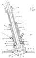
- An electrode holder 3 supports by means of strips 4 a cap 5 with a forward sealing member 6.
- the electrode holder 3 has a back sealing member 7 and an intermediate sealing member 8.
- the electrode holder 3 has a sleeve with at its back side a part with internal screw thread 15 of larger diameter than a cylindrical part with a thick wall 9 and beyond the back sealing member 7 a cylindrical part 10 with a wall of small thickness, which at its end is provided with a shoulder 11.
- a gasket 12 on which an internal sleeve 13 can exert an axial force to press him against the electrode 2 in order to form therewith a seal and to retain the electrode in the sleeve 9,10.
- a pressure ring 14 acts on the internal sleeve 13, which ring can be pressed by means of a not shown gland cooperating with the screw thread 15 at the back side of the sleeve.
- the electrode holder 3 is located in a sleeve, which consists of two organs 16 and 17, which by means of a mounting nut 18 are connected to each other, wherewith a gasket 19 provides a seal.
- the sleeve consisting of the organs 16 and 17 has first a cylindrical inner wall 20 with a first diameter, then via tapered wall parts a cylindrical part 21 with a larger diameter and after this again a cylindrical part 22 with the same diameter as the part 20. In the part 21 with the larger diameter connection ducts 23 and 24 debouch.
- the head or measuring part 1 of the electrode protrudes into the liquid which is contained in a reaction vessel limited by the wall 25.
- This wall is welded to a weld flange 26, which is part of the sleeve organ 16, it being clear that in the wall 25 only a perpendicular hole has to be made and that also welding in an oblique position is not necessary.
- the organ 16 has a spherical shape 27. In the work position shown in fig. 1 the outside of the part 27 is by means of the seal 8 sealed from the cylindrical space between the wall parts 20 and 21 and the sleeve organ 16 respectively 17.
- the forward sealing member 6 forms a seal with the bore 20 of the organ 16.
- the wall part between the sealing members 6 and 8 can therewith not contain other micro-organisms as already were present in the process liquid.
- the forward sealing member 6 is further shifted inwardly and the intermediate sealing member 8 lies now opposite the enlarged bore wall part 21.
- the measuring part 1 of the electrode is located in a space, which is connected with the connection ducts 23 and 24, by reason of which sterilization or standardization is possible.
- the concerned processes for instance fermentation processes
- the electrode By unscrewing the now shown gland which cooperates with the screw thread 15 the electrode can be taken out of the sleeve 3 and a new electrode can be mounted, which by fastening of the not shown gland in the screw thread 15 is fixed. It is now possible to sterilize the electrode and the concerned part of the inner wall of the organ 16.
- the connection between the sterilization agent supply and the electrode is interrupted. Shortly after this the cooperation between the forward sealing member 6 and the organ 16 ends and the electrode protrudes again in the liquid to do its job.
- An additional advantage of the invention is, that in the position of fig. 2 a sluice chamber is formed between the sealing members 6 and 8.
- the liquid quantity contained in this chamber can be monitored by the electrode to check any measurable process in the sample. Afterwards the sample can be re-introduced in the process vessel or be removed in the position of fig. 3 by venting through the ducts 23 and 24.
Landscapes
- Chemical & Material Sciences (AREA)
- Life Sciences & Earth Sciences (AREA)
- Health & Medical Sciences (AREA)
- Physics & Mathematics (AREA)
- Chemical Kinetics & Catalysis (AREA)
- Electrochemistry (AREA)
- Molecular Biology (AREA)
- Analytical Chemistry (AREA)
- Biochemistry (AREA)
- General Health & Medical Sciences (AREA)
- General Physics & Mathematics (AREA)
- Immunology (AREA)
- Pathology (AREA)
- Apparatus Associated With Microorganisms And Enzymes (AREA)
- Electrical Discharge Machining, Electrochemical Machining, And Combined Machining (AREA)
Claims (7)
Priority Applications (2)
| Application Number | Priority Date | Filing Date | Title |
|---|---|---|---|
| EP19880202757 EP0372121B1 (fr) | 1988-12-02 | 1988-12-02 | Dispositif d'appui pour fixation d'électrode |
| DE8888202757T DE3868935D1 (de) | 1988-12-02 | 1988-12-02 | Vorrichtung zum festhalten eines elektrodenhalters. |
Applications Claiming Priority (1)
| Application Number | Priority Date | Filing Date | Title |
|---|---|---|---|
| EP19880202757 EP0372121B1 (fr) | 1988-12-02 | 1988-12-02 | Dispositif d'appui pour fixation d'électrode |
Publications (2)
| Publication Number | Publication Date |
|---|---|
| EP0372121A1 EP0372121A1 (fr) | 1990-06-13 |
| EP0372121B1 true EP0372121B1 (fr) | 1992-03-04 |
Family
ID=8199885
Family Applications (1)
| Application Number | Title | Priority Date | Filing Date |
|---|---|---|---|
| EP19880202757 Expired EP0372121B1 (fr) | 1988-12-02 | 1988-12-02 | Dispositif d'appui pour fixation d'électrode |
Country Status (2)
| Country | Link |
|---|---|
| EP (1) | EP0372121B1 (fr) |
| DE (1) | DE3868935D1 (fr) |
Cited By (6)
| Publication number | Priority date | Publication date | Assignee | Title |
|---|---|---|---|---|
| US7272983B2 (en) | 2002-09-09 | 2007-09-25 | Mettler-Toledo Ag | Probe-holder armature with a sensor probe |
| US7806009B2 (en) | 2006-06-23 | 2010-10-05 | Mettler-Toledo Ag | Immersion tube for a measuring probe |
| DE102010001779A1 (de) | 2010-02-10 | 2011-08-11 | Hamilton Bonaduz Ag | Kalibrierbare Sensoreinheit für Reaktionsbehälter |
| CN102759553A (zh) * | 2011-04-26 | 2012-10-31 | 恩德莱斯和豪瑟尔测量及调节技术分析仪表两合公司 | 测量过程容器中包含的过程介质的被测变量的探针系统 |
| CN101573610B (zh) * | 2006-12-21 | 2013-01-02 | 恩德莱斯和豪瑟尔测量及调节技术分析仪表两合公司 | 可换式配件 |
| US12313586B2 (en) | 2017-09-22 | 2025-05-27 | Broadley-James Corporation | Sensing element for use with media-preserving storage and calibration chamber |
Families Citing this family (18)
| Publication number | Priority date | Publication date | Assignee | Title |
|---|---|---|---|---|
| DE59001999D1 (de) * | 1989-03-02 | 1993-08-26 | Ciba Geigy Ag | Vorrichtung zur erfassung chemischer ausgleichsvorgaenge in waessriger loesung. |
| AU8215291A (en) * | 1990-07-10 | 1992-02-04 | Amagruss Limited | Sensor holder |
| DE4440580A1 (de) * | 1994-11-14 | 1996-05-15 | Kurt Schwabe Inst Fuer Mes Und | Meß- und Kalibrierzelle zur Adaption von Sensoren an Rohrströmungen |
| JP3391945B2 (ja) * | 1995-07-08 | 2003-03-31 | 株式会社堀場製作所 | イオン濃度測定装置 |
| US6235123B1 (en) * | 1998-05-04 | 2001-05-22 | Honeywell-Measorek Corporation | Chemical cleaning system for electrodes used in a liquid environment |
| DE10024564A1 (de) * | 2000-05-19 | 2001-11-22 | Knick Elektronische Mesgeraete | Sondeneinrichtung zur Aufnahme, Positionierung, Kalibrierung und/oder Wartung einer Meßelektrode |
| DE10241834A1 (de) | 2002-09-09 | 2004-03-25 | Mettler-Toledo Gmbh | Spülvorrichtung für einen Sensor |
| DE102005036865B4 (de) * | 2005-08-02 | 2009-02-12 | Knick Elektronische Messgeräte GmbH & Co. KG | Sondeneinrichtung zur Messung von Prozessgrößen, insbesondere physikalisch-chemischer Messgrößen, in Fluiden |
| EP1790981A1 (fr) * | 2005-11-28 | 2007-05-30 | Siemens Aktiengesellschaft | Appareil et procédé de maintenance d'un dispositif dans un canal d'écoulement |
| DE102006022977B4 (de) * | 2006-05-15 | 2016-09-15 | Knick Elektronische Messgeräte GmbH & Co. KG | Sondeneinrichtung zur Messung von Prozessgrößen, insbesondere Schubstangenarmatur |
| DE102006048898B4 (de) * | 2006-10-17 | 2010-09-09 | Knick Elektronische Messgeräte GmbH & Co. KG | Sondeneinrichtung zur Messung von Prozessgrößen, insbesondere Schubstangenarmatur |
| DE102007059668A1 (de) * | 2007-12-10 | 2009-06-25 | Endress + Hauser Conducta Gesellschaft für Mess- und Regeltechnik mbH + Co. KG | Tauchwechselarmatur |
| DE102007059670A1 (de) * | 2007-12-10 | 2009-06-25 | Endress + Hauser Conducta Gesellschaft für Mess- und Regeltechnik mbH + Co. KG | Tauchwechselarmatur |
| DE102008054884A1 (de) * | 2008-12-18 | 2010-07-01 | Endress + Hauser Conducta Gesellschaft für Mess- und Regeltechnik mbH + Co. KG | Wechselaramatur für einen Sensor |
| DE102009037345A1 (de) | 2009-06-16 | 2010-12-23 | Sartorius Stedim Biotech Gmbh | Behälter mit einem Sensoradapter |
| DE102009046637B4 (de) | 2009-11-11 | 2017-08-03 | Endress+Hauser Conducta Gmbh+Co. Kg | Sondeneinrichtung zum Messen einer Messgröße eines in einem Prozessbehälter enthaltenen Fluids, insbesondere für sterile Anwendungen |
| DE102010061836A1 (de) * | 2010-11-24 | 2012-05-24 | Endress + Hauser Flowtec Ag | Austrittssicherung |
| AT12618U1 (de) * | 2011-05-30 | 2012-08-15 | Gilhofer Andree Mag | Verfahren und vorrichtung zu einer von ausserhalb möglichen wartung, reinigung und kalibrierung von elektroanalytischen messeinrichtungen in gülle |
Family Cites Families (4)
| Publication number | Priority date | Publication date | Assignee | Title |
|---|---|---|---|---|
| DE3118771C2 (de) * | 1981-05-12 | 1984-01-19 | Helmuth Dr. 6368 Bad Vilbel Galster | Vorrichtung für elektrochemische Messungen, insbesondere pH-Messungen, mit einer Einrichtung zur Reinigung der Meßelektrode und/oder Nacheichung einer Meßkette |
| CH670158A5 (fr) * | 1985-05-30 | 1989-05-12 | Proton Ag | |
| DE3643036A1 (de) * | 1986-12-17 | 1988-06-30 | Conducta Mess & Regeltech | Halterung fuer elektroden in der analytischen chemie |
| DE8706309U1 (de) * | 1987-05-02 | 1988-09-01 | Knick Elektronische Meßgeräte GmbH & Co, 1000 Berlin | Vorrichtung zum Messen insbesondere des pH-Wertes von Flüssigkeiten |
-
1988
- 1988-12-02 DE DE8888202757T patent/DE3868935D1/de not_active Expired - Lifetime
- 1988-12-02 EP EP19880202757 patent/EP0372121B1/fr not_active Expired
Cited By (9)
| Publication number | Priority date | Publication date | Assignee | Title |
|---|---|---|---|---|
| US7272983B2 (en) | 2002-09-09 | 2007-09-25 | Mettler-Toledo Ag | Probe-holder armature with a sensor probe |
| US7806009B2 (en) | 2006-06-23 | 2010-10-05 | Mettler-Toledo Ag | Immersion tube for a measuring probe |
| CN101093209B (zh) * | 2006-06-23 | 2013-04-03 | 梅特勒-托利多公开股份有限公司 | 用于测量探头的浸入管 |
| CN101573610B (zh) * | 2006-12-21 | 2013-01-02 | 恩德莱斯和豪瑟尔测量及调节技术分析仪表两合公司 | 可换式配件 |
| DE102010001779A1 (de) | 2010-02-10 | 2011-08-11 | Hamilton Bonaduz Ag | Kalibrierbare Sensoreinheit für Reaktionsbehälter |
| EP2363704A1 (fr) | 2010-02-10 | 2011-09-07 | Hamilton Bonaduz AG | Unité de détection pouvant être calibrée pour récipients de réaction |
| CN102759553A (zh) * | 2011-04-26 | 2012-10-31 | 恩德莱斯和豪瑟尔测量及调节技术分析仪表两合公司 | 测量过程容器中包含的过程介质的被测变量的探针系统 |
| CN102759553B (zh) * | 2011-04-26 | 2015-03-11 | 恩德莱斯和豪瑟尔测量及调节技术分析仪表两合公司 | 测量过程容器中包含的过程介质的被测变量的探针系统 |
| US12313586B2 (en) | 2017-09-22 | 2025-05-27 | Broadley-James Corporation | Sensing element for use with media-preserving storage and calibration chamber |
Also Published As
| Publication number | Publication date |
|---|---|
| EP0372121A1 (fr) | 1990-06-13 |
| DE3868935D1 (de) | 1992-04-09 |
Similar Documents
| Publication | Publication Date | Title |
|---|---|---|
| EP0372121B1 (fr) | Dispositif d'appui pour fixation d'électrode | |
| US4669321A (en) | Sample taking device | |
| GB2105291A (en) | Aseptic filling of containers | |
| US4941517A (en) | Aseptic fluid transfer apparatus and methods | |
| DE3064816D1 (en) | Apparatus for disinfecting flowable media | |
| US5269350A (en) | Aseptic fluid transfer apparatus and methods | |
| CN102103113A (zh) | 用于测量容纳在特别是消毒用的过程容器中的流体的测量变量的探头系统 | |
| GB2192622A (en) | Filling valve for counterpressure filling of cans | |
| EP0187892B1 (fr) | Raccord séparable pour récipients | |
| CA2581984C (fr) | Vanne d'echantillonnage aseptique | |
| EP0236107A1 (fr) | Station de remplissage aseptique | |
| US5086813A (en) | Aseptic fluid transfer methods | |
| US20190247842A1 (en) | Aseptic sampling apparatus and sampling method using the same | |
| AU642999B2 (en) | Method for sterilizing an enclosure with noncondensing hydrogen peroxide-containing gas | |
| JPH0277258A (ja) | 現物の機器を殺菌すべき容器又は配管に接続する為の方法および接続バルブ | |
| ATE53553T1 (de) | Aseptische abfuellanlage. | |
| US3826396A (en) | Double seal closure plug | |
| JP3209947B2 (ja) | 液体充填装置 | |
| US5615859A (en) | Sterilizable valve assembly | |
| JP2900275B2 (ja) | 全自動計測用センサーシステム | |
| JPS61500768A (ja) | 器具の滅菌及び無菌保管用ケ−ス | |
| JPS63248605A (ja) | 袋への流体の無菌充填方法 | |
| JP3007966U (ja) | シール構造 | |
| JPH0426325Y2 (fr) | ||
| JPH054019B2 (fr) |
Legal Events
| Date | Code | Title | Description |
|---|---|---|---|
| PUAI | Public reference made under article 153(3) epc to a published international application that has entered the european phase |
Free format text: ORIGINAL CODE: 0009012 |
|
| 17P | Request for examination filed |
Effective date: 19891128 |
|
| AK | Designated contracting states |
Kind code of ref document: A1 Designated state(s): BE CH DE FR GB IT LI LU NL |
|
| 17Q | First examination report despatched |
Effective date: 19901017 |
|
| RAP1 | Party data changed (applicant data changed or rights of an application transferred) |
Owner name: YOKOGAWA EUROPE B.V. |
|
| GRAA | (expected) grant |
Free format text: ORIGINAL CODE: 0009210 |
|
| AK | Designated contracting states |
Kind code of ref document: B1 Designated state(s): BE CH DE FR GB IT LI LU NL |
|
| REF | Corresponds to: |
Ref document number: 3868935 Country of ref document: DE Date of ref document: 19920409 |
|
| ITF | It: translation for a ep patent filed | ||
| ET | Fr: translation filed | ||
| PLBE | No opposition filed within time limit |
Free format text: ORIGINAL CODE: 0009261 |
|
| STAA | Information on the status of an ep patent application or granted ep patent |
Free format text: STATUS: NO OPPOSITION FILED WITHIN TIME LIMIT |
|
| 26N | No opposition filed | ||
| EPTA | Lu: last paid annual fee | ||
| PGFP | Annual fee paid to national office [announced via postgrant information from national office to epo] |
Ref country code: BE Payment date: 19961108 Year of fee payment: 9 |
|
| PGFP | Annual fee paid to national office [announced via postgrant information from national office to epo] |
Ref country code: GB Payment date: 19961125 Year of fee payment: 9 |
|
| PGFP | Annual fee paid to national office [announced via postgrant information from national office to epo] |
Ref country code: LU Payment date: 19961201 Year of fee payment: 9 |
|
| PGFP | Annual fee paid to national office [announced via postgrant information from national office to epo] |
Ref country code: CH Payment date: 19961216 Year of fee payment: 9 |
|
| PGFP | Annual fee paid to national office [announced via postgrant information from national office to epo] |
Ref country code: FR Payment date: 19961224 Year of fee payment: 9 |
|
| PGFP | Annual fee paid to national office [announced via postgrant information from national office to epo] |
Ref country code: DE Payment date: 19970124 Year of fee payment: 9 |
|
| PG25 | Lapsed in a contracting state [announced via postgrant information from national office to epo] |
Ref country code: LU Free format text: LAPSE BECAUSE OF NON-PAYMENT OF DUE FEES Effective date: 19971202 Ref country code: GB Free format text: LAPSE BECAUSE OF NON-PAYMENT OF DUE FEES Effective date: 19971202 |
|
| PG25 | Lapsed in a contracting state [announced via postgrant information from national office to epo] |
Ref country code: LI Free format text: LAPSE BECAUSE OF NON-PAYMENT OF DUE FEES Effective date: 19971231 Ref country code: FR Free format text: THE PATENT HAS BEEN ANNULLED BY A DECISION OF A NATIONAL AUTHORITY Effective date: 19971231 Ref country code: CH Free format text: LAPSE BECAUSE OF NON-PAYMENT OF DUE FEES Effective date: 19971231 Ref country code: BE Free format text: LAPSE BECAUSE OF NON-PAYMENT OF DUE FEES Effective date: 19971231 |
|
| BERE | Be: lapsed |
Owner name: YOKOGAWA EUROPE B.V. Effective date: 19971231 |
|
| GBPC | Gb: european patent ceased through non-payment of renewal fee |
Effective date: 19971202 |
|
| REG | Reference to a national code |
Ref country code: CH Ref legal event code: PL |
|
| PG25 | Lapsed in a contracting state [announced via postgrant information from national office to epo] |
Ref country code: DE Free format text: LAPSE BECAUSE OF NON-PAYMENT OF DUE FEES Effective date: 19980901 |
|
| REG | Reference to a national code |
Ref country code: FR Ref legal event code: ST |
|
| PGFP | Annual fee paid to national office [announced via postgrant information from national office to epo] |
Ref country code: NL Payment date: 19981231 Year of fee payment: 11 |
|
| PG25 | Lapsed in a contracting state [announced via postgrant information from national office to epo] |
Ref country code: NL Free format text: LAPSE BECAUSE OF NON-PAYMENT OF DUE FEES Effective date: 20000701 |
|
| NLV4 | Nl: lapsed or anulled due to non-payment of the annual fee |
Effective date: 20000701 |
|
| PG25 | Lapsed in a contracting state [announced via postgrant information from national office to epo] |
Ref country code: IT Free format text: LAPSE BECAUSE OF NON-PAYMENT OF DUE FEES;WARNING: LAPSES OF ITALIAN PATENTS WITH EFFECTIVE DATE BEFORE 2007 MAY HAVE OCCURRED AT ANY TIME BEFORE 2007. THE CORRECT EFFECTIVE DATE MAY BE DIFFERENT FROM THE ONE RECORDED. Effective date: 20051202 |