EP0372127A1 - Verfahren und Vorrichtung zur Bestimmung der Bestrahlungsdosis - Google Patents
Verfahren und Vorrichtung zur Bestimmung der Bestrahlungsdosis Download PDFInfo
- Publication number
- EP0372127A1 EP0372127A1 EP88311358A EP88311358A EP0372127A1 EP 0372127 A1 EP0372127 A1 EP 0372127A1 EP 88311358 A EP88311358 A EP 88311358A EP 88311358 A EP88311358 A EP 88311358A EP 0372127 A1 EP0372127 A1 EP 0372127A1
- Authority
- EP
- European Patent Office
- Prior art keywords
- thickness
- membrane
- radiation
- maximum
- cornea
- Prior art date
- Legal status (The legal status is an assumption and is not a legal conclusion. Google has not performed a legal analysis and makes no representation as to the accuracy of the status listed.)
- Withdrawn
Links
- 238000000034 method Methods 0.000 title claims description 48
- 230000005855 radiation Effects 0.000 claims abstract description 74
- 230000004907 flux Effects 0.000 claims abstract description 16
- 239000012528 membrane Substances 0.000 claims description 103
- 210000004087 cornea Anatomy 0.000 claims description 54
- 238000002679 ablation Methods 0.000 claims description 22
- 238000009826 distribution Methods 0.000 claims description 22
- 239000000758 substrate Substances 0.000 claims description 20
- 239000000463 material Substances 0.000 claims description 15
- 230000003287 optical effect Effects 0.000 claims description 15
- 230000035515 penetration Effects 0.000 claims description 13
- 208000001491 myopia Diseases 0.000 claims description 12
- 230000009467 reduction Effects 0.000 claims description 12
- 206010020675 Hypermetropia Diseases 0.000 claims description 11
- 201000009310 astigmatism Diseases 0.000 claims description 11
- 201000006318 hyperopia Diseases 0.000 claims description 11
- 238000004519 manufacturing process Methods 0.000 claims description 10
- 230000008859 change Effects 0.000 claims description 9
- 230000003247 decreasing effect Effects 0.000 claims description 6
- -1 poly(terephthalate) Polymers 0.000 claims description 6
- 238000000576 coating method Methods 0.000 claims description 5
- 238000000354 decomposition reaction Methods 0.000 claims description 5
- 230000005540 biological transmission Effects 0.000 claims description 4
- 239000011248 coating agent Substances 0.000 claims description 4
- 238000006303 photolysis reaction Methods 0.000 claims description 4
- 229920002799 BoPET Polymers 0.000 claims description 2
- 239000005041 Mylar™ Substances 0.000 claims description 2
- 239000004642 Polyimide Substances 0.000 claims description 2
- 230000009471 action Effects 0.000 claims description 2
- 230000015572 biosynthetic process Effects 0.000 claims description 2
- 230000001427 coherent effect Effects 0.000 claims description 2
- 229920001721 polyimide Polymers 0.000 claims description 2
- 206010073306 Exposure to radiation Diseases 0.000 claims 7
- 230000001154 acute effect Effects 0.000 claims 1
- 238000012937 correction Methods 0.000 abstract description 15
- 238000001356 surgical procedure Methods 0.000 abstract description 10
- 230000007257 malfunction Effects 0.000 abstract 1
- 230000004305 hyperopia Effects 0.000 description 5
- 230000004379 myopia Effects 0.000 description 5
- 230000000694 effects Effects 0.000 description 4
- 238000002430 laser surgery Methods 0.000 description 4
- VYPSYNLAJGMNEJ-UHFFFAOYSA-N Silicium dioxide Chemical compound O=[Si]=O VYPSYNLAJGMNEJ-UHFFFAOYSA-N 0.000 description 2
- 238000005520 cutting process Methods 0.000 description 2
- 230000004048 modification Effects 0.000 description 2
- 238000012986 modification Methods 0.000 description 2
- 238000012360 testing method Methods 0.000 description 2
- 208000027418 Wounds and injury Diseases 0.000 description 1
- 230000002159 abnormal effect Effects 0.000 description 1
- 230000005856 abnormality Effects 0.000 description 1
- ISQINHMJILFLAQ-UHFFFAOYSA-N argon hydrofluoride Chemical compound F.[Ar] ISQINHMJILFLAQ-UHFFFAOYSA-N 0.000 description 1
- OYLGJCQECKOTOL-UHFFFAOYSA-L barium fluoride Chemical compound [F-].[F-].[Ba+2] OYLGJCQECKOTOL-UHFFFAOYSA-L 0.000 description 1
- 229910001632 barium fluoride Inorganic materials 0.000 description 1
- 230000008901 benefit Effects 0.000 description 1
- WUKWITHWXAAZEY-UHFFFAOYSA-L calcium difluoride Chemical compound [F-].[F-].[Ca+2] WUKWITHWXAAZEY-UHFFFAOYSA-L 0.000 description 1
- 229910001634 calcium fluoride Inorganic materials 0.000 description 1
- 230000015556 catabolic process Effects 0.000 description 1
- 230000005779 cell damage Effects 0.000 description 1
- 208000037887 cell injury Diseases 0.000 description 1
- 239000013065 commercial product Substances 0.000 description 1
- 238000011161 development Methods 0.000 description 1
- 238000010586 diagram Methods 0.000 description 1
- 239000012634 fragment Substances 0.000 description 1
- 239000005350 fused silica glass Substances 0.000 description 1
- 238000010438 heat treatment Methods 0.000 description 1
- 230000006872 improvement Effects 0.000 description 1
- 238000011065 in-situ storage Methods 0.000 description 1
- 238000000608 laser ablation Methods 0.000 description 1
- ORUIBWPALBXDOA-UHFFFAOYSA-L magnesium fluoride Chemical compound [F-].[F-].[Mg+2] ORUIBWPALBXDOA-UHFFFAOYSA-L 0.000 description 1
- 229910001635 magnesium fluoride Inorganic materials 0.000 description 1
- 230000014759 maintenance of location Effects 0.000 description 1
- 230000007246 mechanism Effects 0.000 description 1
- 230000000149 penetrating effect Effects 0.000 description 1
- 230000000649 photocoagulation Effects 0.000 description 1
- 229920000139 polyethylene terephthalate Polymers 0.000 description 1
- 239000005020 polyethylene terephthalate Substances 0.000 description 1
- 238000002360 preparation method Methods 0.000 description 1
- 238000012545 processing Methods 0.000 description 1
- 231100000241 scar Toxicity 0.000 description 1
- 238000007493 shaping process Methods 0.000 description 1
- 238000001228 spectrum Methods 0.000 description 1
- 230000007704 transition Effects 0.000 description 1
- 238000002054 transplantation Methods 0.000 description 1
Images
Classifications
-
- A—HUMAN NECESSITIES
- A61—MEDICAL OR VETERINARY SCIENCE; HYGIENE
- A61F—FILTERS IMPLANTABLE INTO BLOOD VESSELS; PROSTHESES; DEVICES PROVIDING PATENCY TO, OR PREVENTING COLLAPSING OF, TUBULAR STRUCTURES OF THE BODY, e.g. STENTS; ORTHOPAEDIC, NURSING OR CONTRACEPTIVE DEVICES; FOMENTATION; TREATMENT OR PROTECTION OF EYES OR EARS; BANDAGES, DRESSINGS OR ABSORBENT PADS; FIRST-AID KITS
- A61F9/00—Methods or devices for treatment of the eyes; Devices for putting in contact-lenses; Devices to correct squinting; Apparatus to guide the blind; Protective devices for the eyes, carried on the body or in the hand
- A61F9/007—Methods or devices for eye surgery
- A61F9/008—Methods or devices for eye surgery using laser
-
- A—HUMAN NECESSITIES
- A61—MEDICAL OR VETERINARY SCIENCE; HYGIENE
- A61F—FILTERS IMPLANTABLE INTO BLOOD VESSELS; PROSTHESES; DEVICES PROVIDING PATENCY TO, OR PREVENTING COLLAPSING OF, TUBULAR STRUCTURES OF THE BODY, e.g. STENTS; ORTHOPAEDIC, NURSING OR CONTRACEPTIVE DEVICES; FOMENTATION; TREATMENT OR PROTECTION OF EYES OR EARS; BANDAGES, DRESSINGS OR ABSORBENT PADS; FIRST-AID KITS
- A61F9/00—Methods or devices for treatment of the eyes; Devices for putting in contact-lenses; Devices to correct squinting; Apparatus to guide the blind; Protective devices for the eyes, carried on the body or in the hand
- A61F9/007—Methods or devices for eye surgery
- A61F9/008—Methods or devices for eye surgery using laser
- A61F9/00802—Methods or devices for eye surgery using laser for photoablation
- A61F9/00804—Refractive treatments
-
- A—HUMAN NECESSITIES
- A61—MEDICAL OR VETERINARY SCIENCE; HYGIENE
- A61F—FILTERS IMPLANTABLE INTO BLOOD VESSELS; PROSTHESES; DEVICES PROVIDING PATENCY TO, OR PREVENTING COLLAPSING OF, TUBULAR STRUCTURES OF THE BODY, e.g. STENTS; ORTHOPAEDIC, NURSING OR CONTRACEPTIVE DEVICES; FOMENTATION; TREATMENT OR PROTECTION OF EYES OR EARS; BANDAGES, DRESSINGS OR ABSORBENT PADS; FIRST-AID KITS
- A61F9/00—Methods or devices for treatment of the eyes; Devices for putting in contact-lenses; Devices to correct squinting; Apparatus to guide the blind; Protective devices for the eyes, carried on the body or in the hand
- A61F9/007—Methods or devices for eye surgery
- A61F9/008—Methods or devices for eye surgery using laser
- A61F9/00802—Methods or devices for eye surgery using laser for photoablation
- A61F9/0081—Transplantation
-
- A—HUMAN NECESSITIES
- A61—MEDICAL OR VETERINARY SCIENCE; HYGIENE
- A61B—DIAGNOSIS; SURGERY; IDENTIFICATION
- A61B17/00—Surgical instruments, devices or methods
- A61B17/30—Surgical pincettes, i.e. surgical tweezers without pivotal connections
- A61B2017/306—Surgical pincettes, i.e. surgical tweezers without pivotal connections holding by means of suction
-
- A—HUMAN NECESSITIES
- A61—MEDICAL OR VETERINARY SCIENCE; HYGIENE
- A61F—FILTERS IMPLANTABLE INTO BLOOD VESSELS; PROSTHESES; DEVICES PROVIDING PATENCY TO, OR PREVENTING COLLAPSING OF, TUBULAR STRUCTURES OF THE BODY, e.g. STENTS; ORTHOPAEDIC, NURSING OR CONTRACEPTIVE DEVICES; FOMENTATION; TREATMENT OR PROTECTION OF EYES OR EARS; BANDAGES, DRESSINGS OR ABSORBENT PADS; FIRST-AID KITS
- A61F9/00—Methods or devices for treatment of the eyes; Devices for putting in contact-lenses; Devices to correct squinting; Apparatus to guide the blind; Protective devices for the eyes, carried on the body or in the hand
- A61F9/007—Methods or devices for eye surgery
- A61F9/008—Methods or devices for eye surgery using laser
- A61F2009/00861—Methods or devices for eye surgery using laser adapted for treatment at a particular location
- A61F2009/00872—Cornea
Definitions
- This invention generally relates to a method and apparatus for modulating the flux distribution onto a surface to be profiled of an ablative radiation beam and has particular though not exclusive application to ophthalmological techniques for laser surgery of the cornea which involve the profiling of the anterior corneal surface to achieve a desired curvature for correction for example of a detected abnormal eye condition, such techniques being useful not only in the in situ treatment of the corneas of living patients but also in relation to donor surgery where they may for example be utilized for the profiling of a donor cornea prior to transplantation.
- the sculpturing technique of my European patent application no. 87306826 may be briefly stated as involving corneal exposure to a laser beam of varying spot size to achieve an ablated change in anterior-surface curvature in the visually used central area of the cornea.
- Various means have been described to achieve this result, and most conveniently the previously described means have involved microprocessor means to assure a given exposure program in the course of which spot-size area varies as predetermined to achieve a given profile change.
- a method of delivering ablative radiation in a predetermined areal flux distribution onto a surface to be ablated comprising introducing into the path of a beam of ablative radiation a member having a predetermined areal thickness distribution and arranging for the beam of radiation to impinge upon said surface after ablation of said member so that the flux delivery distribution is modulated by the thickness distribution of said member.
- a device for modulating the areal flux distribution within a beam of ablative radiation comprising material opaque to said radiation and having a predetermined areal thickness distribution such that when the device is placed in said beam ablation of said material produces a differential beam breakthrough distribution such as to modulate the areal flux distribution of the breakthrough beam.
- the present invention provides a beam modulation technique which depends for its operation upon different breakthrough or burnthrough rates being established in a device inserted into the ablative beam so that for a predetermined beam exposure time a surface to be ablated will receive differential flux levels at different locations thereof.
- the invention provides an improved method and means for variable-spot-size laser sculpture of the anterior surface of the cornea to achieve an optical improvement of the involved eye.
- a specific advantage of the invention is that this is achieved with simplified techniques which do not require microprocessor control of spot-size variation.
- Another specific application of the present invention resides in providing the ophthalmic surgeon with an inventory of differently precharacterized disposable elements in accordance with the invention which can be selected from inventory in accordance with the optical change to be achieved, so that, for example, the surgeon can select, e.g., in diopter-related increments, for plus or minus spherical change and/or for plus or minus cylindrical change, the change he deems necessary to improve the optical performance of a given eye.
- the invention provides, for example, an inventory of disposable elements adapted for selective placement in the path of laser-beam delivery to the cornea.
- Each of the disposable elements carries a membrane which is opaque to the laser beam and which is designedly subject to ablation when exposed to the laser beam, the thickness of the membrane being a precharacterized function of local area such that a give laser-beam course of the exposure will require greater or lesser time to locally ablate the membrane and thus permit laser-beam exposure past the membrane and into correspondingly localized ablating impingement with the cornea.
- varying-spot size at the cornea is achieved by a time-release function of the membrane, on a predetermined area-controlled basis that is designed to achieve the diopter change specifically identified with each particular selectable element.
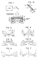
- FIG. 1 the invention is shown in application to an eye-retaining device 10 which may be as described in US Patent No. 4,665,913.
- Device 10 may thus be a hollow annulus, having a convergent axial- end wall 11 of air-permeable material contoured to engage and retain an eye via a scleral-corneal region.
- a side-port connection 12 to a vacuum pump enables retention of engagement of wall 11 to the cornea 14 to be operated upon, and, optionally, the device 10 may be fixedly referenced to associated laser apparatus (by means not shown).
- the laser apparatus is an excimer laser, committed to pulsed ultraviolet radiation at 200 nanometers or less, as for example provided at 193 nm by an argon-fluoride laser.
- the output beam of the laser is processed for shaping and for homogeneity of flux distribution, for directional projection of a homogenized coherent beam of circular section (e.g., of 5 or 6-mm diameter) that is centrally aligned with the optical axis 15 of the eye.
- a homogenized coherent beam of circular section e.g., of 5 or 6-mm diameter
- Means for processing the output of an excimer laser to produce such a homogenized beam of circular section are described in detail in European Patent application no. 88300789 and therefore need not now be further amplified, being identified by suitable legend in Fig. 1.
- an ablatable membrane 16 of suitably precharacterized thickness distribution is selectively positionable in the path of laser beam projection on axis 15.
- the membrane 16 is a coating on the upper surface of a plane-parallel supporting substrate 17 of material that is transparent to the laser beam; a suitable material for this substrate purpose is a synthetic fused silica (e.g., Suprasil, a commercial product of Heraeus-Amersil), or a fluoride compound, such as calcium fluoride, magnesium fluoride, or barium fluoride.
- substrate 17 is seated upon the inward annular flange 18 of a ring member 19, which is adapted, via a depending flange 20, for concentric engagement to the circular upper rim edge of the eye-retaining device 10.
- the membrane 16 is ablatable under action of the laser beam at a rate which preferably (although not necessarily) corresponds with the rate of laser-beam ablative penetration into the stroma of the cornea.
- the maximum thickness of the ablatable membrane 16 is such that, for the maximum extent of stroma penetration involved in a particular corrective procedure, the surgical exposure can be terminated when the entire maximum thickness of exposed membrane is observed to have been ablatively removed.
- Suitable materials for the ablatable membrane 16 include polyimide, Mylar and poly(ethylene terephthalate).
- Fig. 2 provides illustration of the vertical- section thickness profile for each of two selectively available elements, each of which is configured to effect a myopia reduction.
- a profile 21 of lesser maximum thickness T1 is seen to reduce from its maximum to zero thickness as a function of decreasing radius about the central axis, for the case of a laser-beam section diameter of 5 mm.
- a profile 22 of greater maximum thickness T2 is also seen to reduce from its maximum to zero thickness as a function of decreasing radius about the central axis.
- the thickness profiles 25-26 shown for membrane 16 in Fig. 4 are respectively illustrative of what is needed in maximum membrane (16) thickness (a) to achieve hyperopia reduction of lesser degree, using the lesser maximum thickness T1, and (b) to achieve hyperopia reduction of great degree, using the greater maximum thickness T2.
- thickness is greatest (T1) at the centre and is a decreasing function of radius to the point of zero thickness at the outer limit of optical correction (e.g., at 2.5 mm radius); in the case of the greater-thickness profile 26, thickness is also greatest (T2) at the centre and is also a decreasing function of radius to the point of zero thickness at the same outer limit of optical correction.
- the resulting sculpture of cornea 14 would be characterized by a sharply defined outer cylindrical wall, but by utilizing the next 0.5 to 0.75mm increment of radius to taper membrane thickness back to maximum, i.e., radically outward of the outer limit of optical correction, it is possible to materially reduce the sharp-edge nature of such a wall.
- the ablation upon the cornea thus produces the hyperopia-reduced profile 27 (Fig. 5) out to the illustrative outer limit of optical correction, and a gently beveled annulus 27′ of relatively smooth transition to the remaining outer unexposed area of the cornea. It will be understood that to produce the "beveled" hyperopia-reducing result described in connection with Figs.
- Figs. 2-3 and 4-5 The ablatable-membrane technique described for the spherically corrective situation in Figs. 2-3 and 4-5, respectively, will be seen to be further applicable to achieve cylindrical correction needed for reducing an astigmatism.
- Fig. 2 is taken as depicting vertical-section profiles wherein the cylindrical axis of astigmatism correction is normal to and through axis of 15 of Fig. 2 and wherein Fig.
- FIG. 2 is no longer understood to depict a thickness profile of revolution, but rather a generally V-shaped channel profile extending along a diametral alignment with respect to ring 19, the described exposure course will achieve a cylindrical reduction of cornea curvature; and if ring 19 is preset in rotation about axis 15 such that the cylindrical reduction is oriented to accord with the diagnosed orientation of the patient's astigmatism, then the astigmatism can be reduced to a prescribed diopter-reducing extent merely by correct selection of the maximum thickness of the thickness-characterized ablatable membrane 16.
- an arrow indicator 28 on ring 19 can be brought by ring rotation into register against an azimuth scale 29 on device 10, to enable precise setting of the orientation for an astigmatism-reducing procedure.
- the thickness-characterized membrane 16 is designed to achieve varying spot-size transmission of stroma-ablating radiation, via a substrate which is transparent to the involved radiation and in this situation, it is particularly convenient to embody the substrate and its ablatable membrane in a circular ring which is self-centering with respect to the optical size of the eye. But requisite transparent substrate materials may prove to be relatively expensive.
- FIG. 1A The fragmentary diagram of Fig. 1A indicates that substrate expense need not be a problem, in the alternative event of using a plane mirror 30 as the substrate which carries a thickness-characterized ablatable membrane 16′.
- mirror 30 is part of a ring element 31 which is insertably located in a circular opening in supporting frame structure 32, the latter being a fixed attachment to the laser housing.
- Mirror 30 is shown inclined at 45° to the incident laser beam so as to fold the same for vertically downward surgical delivery to the cornea 14, to the progressively varying spot-size extent determined by ablation of membrane 16′ in the course of a given surgical procedure.
- the laser beam Before incidence with the membrane-coated surface of element 31, the laser beam will be understood to be of homogeneously distributed flux density across its circular section, which may again be of 5 or 6 mm diameter for a myopia-reducing procedure. But at incidence with the membrane-coated surface, the area of incidence is an ellipse wherein the minor axis is horizontal; and the thickness profile at the minor axis will be understood to be as depicted in Fig. 2, for a minor-axis extent of 5 mm, the extent shown in Fig. 2. On the other hand, the major-axis extent will be greater, being shown as 7.08 mm in Fig.
- the initially reflected beam will be a central spot of circular section, and this post will progressively expand as the characterized membrane is progressively ablated, until the full circular section of the incident laser beam is reflected into surgical incidence with the cornea; at this point, the surgical procedure will have accomplished the prescribed myopia reduction at the anterior surface of the cornea.
- a keying slot-and-stud engagement is schematically shown at 35 between a point on ring 31 and a reference point on structure 32.
- the described invention will be seen to have achieved all stated objects and to provide methods and means for more readily and economically performing a laser-ablated recurvature of the cornea.
- the surgeon's inventory of membrane-coated rings 19 (or 31) may be precharacterized by thicknesses and thickness profiles which can be labeled in terms well understood by all ophthalmic surgeons, namely in diopters or fractions thereof, and qualified as to plus and minus spherical, with or without the cylindrically correcting feature.
- the rings 19 may be prepared by applying standardized coatings 16 of substrates 17, in thicknesses graduated for successive increments of predetermined ultimate stroma penetrations to achieve given diopter changes; and the uniform-thickness membrane layer may be "cut" to its precharacterizing thickness profile, by laser ablation pursuant to the teachings of one or more of my previously filed European patent applications.
- the uniform-thickness membrane layer may be "cut" to its precharacterizing thickness profile, by laser ablation pursuant to the teachings of one or more of my previously filed European patent applications.
- Figs. 8/9 or 15/16, respectively of European patent application no. 87306826 one may prepare for inventory a plurality of rings 19 having membranes 16 with the Fig. 2 spherical or cylindrical correcting thickness profiles; and by using the apparatus of Fig. 30 of said European application one may prepare for further inventory a plurality of such rings 19 having membranes 16 with the Fig 4 thickness profiles.
- manufacture of thickness-characterized reflection rings 31 for use in Fig. 1A is as simple and straightforward as was the case for transmission rings 19 for use in Fig. 1.
- a uniformly thick (T1 or T2) membrane 16′ should be inclined at 45° to the incident homogeneous circular beam when precharacterizing the same. Such inclination will enable automatic development of the described profile, with correct elliptical proportioning and orientation, using the keying reference 35.
- rings 31 which are characterized for astigmatism correction
- the astigmatism-reducing apparatus of Figs. 15/16 of European patent application no. 87306826 is selectively adjustable for azimuth orientation, and is well suited to prepare such a series of rings 31.
- zero thickness as applied herein to describe one of the limits of precharacterized thickness profiling of membrane 16 (or 16′) is to be understood as a convenient way of stating (together with the expression “maximum thickness”) the range of thickness variation involved in precharacterization to achieve a given recurvature profile of the cornea.
- maximum thickness the range of thickness variation involved in precharacterization to achieve a given recurvature profile of the cornea.
- it may be further convenient or desirable to avoid a truly zero thickness as for example to provide such added uniformly distributed thickness of membrane 16 (of 16′) beneath the described profiling as to permit the surgeon to perform a testing of a given membrane 16 (or 16′), for example, prior to its use for sculpture of a cornea.
- a test exposure of the homogenized beam to the thus-characterized membrane could illustratively enable the surgeon to determine, as with his stop watch, the time required to expose to the extent of ablative decomposition of the added uniform-thickness increment, such time being visually observed to terminate upon initial laser-beam emergence at the region of least-thickness of the membrane.
- the surgeon determines this time, he has in effect calibrated his inserted membrane for its rate of penetrating ablation of the membrane material, thus establishing whether he has selected an element 19 (or 31) with a membrane having the correct diopter-changing value which he has prescribed, or whether he should achieve the prescription by selecting a different ring 19 (or 31) with a membrane designed for its incrementally greater or lesser diopter-changing property.
- an element 19 (or 31) having a membrane 16 (or 16′) that is characterized by known uniform thickness may be a calibrating device forming part of the surgeon's inventory, in that his timing of this laser's ability to ablate through the full membrane thickness of such an element will enable him to immediately determine the current ablating efficacy of his laser beam, thus enabling his appropriate allowance for a drop in ablating efficacy, merely by selecting for a given sculpturing procedure an element 19 (31) having a thickness-characterized membrane 16 (16′) that was designed for a laser diopter-changing property, i.e., of lesser maximum thickness.
- the ablative radiation is not restricted to laser radiation and particularly not to the ultraviolet region of the electromagnetic spectrum (infrared radiation might for example be used for some applications), and the invention is not limited to the field of ophthalmological surgery though it is considered to be especially useful therefor.
Landscapes
- Health & Medical Sciences (AREA)
- Ophthalmology & Optometry (AREA)
- Biomedical Technology (AREA)
- Heart & Thoracic Surgery (AREA)
- Nuclear Medicine, Radiotherapy & Molecular Imaging (AREA)
- Physics & Mathematics (AREA)
- Surgery (AREA)
- Engineering & Computer Science (AREA)
- Veterinary Medicine (AREA)
- Optics & Photonics (AREA)
- Vascular Medicine (AREA)
- Life Sciences & Earth Sciences (AREA)
- Animal Behavior & Ethology (AREA)
- General Health & Medical Sciences (AREA)
- Public Health (AREA)
- Transplantation (AREA)
- Laser Surgery Devices (AREA)
- Radiation-Therapy Devices (AREA)
Priority Applications (1)
| Application Number | Priority Date | Filing Date | Title |
|---|---|---|---|
| EP88311358A EP0372127A1 (de) | 1988-11-30 | 1988-11-30 | Verfahren und Vorrichtung zur Bestimmung der Bestrahlungsdosis |
Applications Claiming Priority (1)
| Application Number | Priority Date | Filing Date | Title |
|---|---|---|---|
| EP88311358A EP0372127A1 (de) | 1988-11-30 | 1988-11-30 | Verfahren und Vorrichtung zur Bestimmung der Bestrahlungsdosis |
Publications (1)
| Publication Number | Publication Date |
|---|---|
| EP0372127A1 true EP0372127A1 (de) | 1990-06-13 |
Family
ID=8200304
Family Applications (1)
| Application Number | Title | Priority Date | Filing Date |
|---|---|---|---|
| EP88311358A Withdrawn EP0372127A1 (de) | 1988-11-30 | 1988-11-30 | Verfahren und Vorrichtung zur Bestimmung der Bestrahlungsdosis |
Country Status (1)
| Country | Link |
|---|---|
| EP (1) | EP0372127A1 (de) |
Cited By (10)
| Publication number | Priority date | Publication date | Assignee | Title |
|---|---|---|---|---|
| US5171254A (en) * | 1991-11-19 | 1992-12-15 | Sher Neal A | Eye fixation device |
| WO1993007820A1 (fr) * | 1991-10-18 | 1993-04-29 | Denis Fauck | Dispositif de support et de guidage d'outils de chirurgie endoscopique |
| US5368590A (en) * | 1992-09-29 | 1994-11-29 | Katsuhiko Mukai | Corneal sponge and method of use |
| US5376086A (en) * | 1993-10-26 | 1994-12-27 | Khoobehi; Bahram | Laser surgical method of sculpting a patient's cornea and associated intermediate controlling mask |
| US5549632A (en) * | 1992-10-26 | 1996-08-27 | Novatec Laser Systems, Inc. | Method and apparatus for ophthalmic surgery |
| US5571107A (en) * | 1993-10-26 | 1996-11-05 | Shaibani; Sanan B. | Laser surgical apparatus for sculpting a cornea using a diffractive optical element and method of using the same |
| US6312424B1 (en) | 1995-07-25 | 2001-11-06 | Allergan | Method of vision correction |
| WO2005011544A1 (de) * | 2003-07-23 | 2005-02-10 | Carl Zeiss Meditec Ag | Verfahren, vorrichtung und system zur bestimmung eines systemparameters eines laserstrahl-behandlungssystems |
| US7220255B2 (en) | 1991-08-02 | 2007-05-22 | Lai Shui T | Method and apparatus for laser surgery of the cornea |
| CN113633462A (zh) * | 2020-05-06 | 2021-11-12 | 施温德眼科技术解决方式有限公司 | 提供用于眼科手术激光器的控制数据的方法、控制装置 |
Citations (4)
| Publication number | Priority date | Publication date | Assignee | Title |
|---|---|---|---|---|
| EP0207648A2 (de) * | 1985-06-06 | 1987-01-07 | Visx Incorporated | Vorrichtung für die ophthalmologische Chirurgie |
| EP0218427A2 (de) * | 1985-09-26 | 1987-04-15 | Visx Incorporated | Vorrichtung für die ophthalmologische Chirurgie |
| WO1987005496A1 (en) * | 1986-03-19 | 1987-09-24 | Summit Technology, Inc. | Surface shaping using lasers |
| EP0280414A1 (de) * | 1987-02-02 | 1988-08-31 | Taunton Technologies, Inc. | Vorrichtung zur Korrektur der Krümmung der Hornhaut |
-
1988
- 1988-11-30 EP EP88311358A patent/EP0372127A1/de not_active Withdrawn
Patent Citations (4)
| Publication number | Priority date | Publication date | Assignee | Title |
|---|---|---|---|---|
| EP0207648A2 (de) * | 1985-06-06 | 1987-01-07 | Visx Incorporated | Vorrichtung für die ophthalmologische Chirurgie |
| EP0218427A2 (de) * | 1985-09-26 | 1987-04-15 | Visx Incorporated | Vorrichtung für die ophthalmologische Chirurgie |
| WO1987005496A1 (en) * | 1986-03-19 | 1987-09-24 | Summit Technology, Inc. | Surface shaping using lasers |
| EP0280414A1 (de) * | 1987-02-02 | 1988-08-31 | Taunton Technologies, Inc. | Vorrichtung zur Korrektur der Krümmung der Hornhaut |
Cited By (12)
| Publication number | Priority date | Publication date | Assignee | Title |
|---|---|---|---|---|
| US7220255B2 (en) | 1991-08-02 | 2007-05-22 | Lai Shui T | Method and apparatus for laser surgery of the cornea |
| WO1993007820A1 (fr) * | 1991-10-18 | 1993-04-29 | Denis Fauck | Dispositif de support et de guidage d'outils de chirurgie endoscopique |
| US5171254A (en) * | 1991-11-19 | 1992-12-15 | Sher Neal A | Eye fixation device |
| WO1993009719A1 (en) * | 1991-11-19 | 1993-05-27 | Sher Neal A | Eye fixation device |
| US5368590A (en) * | 1992-09-29 | 1994-11-29 | Katsuhiko Mukai | Corneal sponge and method of use |
| US5549632A (en) * | 1992-10-26 | 1996-08-27 | Novatec Laser Systems, Inc. | Method and apparatus for ophthalmic surgery |
| US5376086A (en) * | 1993-10-26 | 1994-12-27 | Khoobehi; Bahram | Laser surgical method of sculpting a patient's cornea and associated intermediate controlling mask |
| US5571107A (en) * | 1993-10-26 | 1996-11-05 | Shaibani; Sanan B. | Laser surgical apparatus for sculpting a cornea using a diffractive optical element and method of using the same |
| US6312424B1 (en) | 1995-07-25 | 2001-11-06 | Allergan | Method of vision correction |
| WO2005011544A1 (de) * | 2003-07-23 | 2005-02-10 | Carl Zeiss Meditec Ag | Verfahren, vorrichtung und system zur bestimmung eines systemparameters eines laserstrahl-behandlungssystems |
| US8303577B2 (en) | 2003-07-23 | 2012-11-06 | Carl Zeiss Meditec Ag | Method device and system for determining a system parameter of a laser beam treatment system |
| CN113633462A (zh) * | 2020-05-06 | 2021-11-12 | 施温德眼科技术解决方式有限公司 | 提供用于眼科手术激光器的控制数据的方法、控制装置 |
Similar Documents
| Publication | Publication Date | Title |
|---|---|---|
| US5507741A (en) | Ophthalmic method for laser surgery of the cornea | |
| US5807379A (en) | Ophthalmic method and apparatus for laser surgery of the cornea | |
| KR930011034B1 (ko) | 레이저 안과 수술장치 | |
| US5423801A (en) | Laser corneal surgery | |
| US5395356A (en) | Correction of presbyopia by photorefractive keratectomy | |
| US5207668A (en) | Method for opthalmological surgery | |
| KR930007906B1 (ko) | 안과 수술장치 | |
| US6641577B2 (en) | Apparatus and method for creating a corneal flap | |
| US5188631A (en) | Method for opthalmological surgery | |
| CA1279103C (en) | Surface erosion using lasers | |
| US5219343A (en) | Apparatus for performing ophthalmogolical surgery | |
| US5713892A (en) | Method and apparatus for combined cylindrical and spherical eye corrections | |
| US4729372A (en) | Apparatus for performing ophthalmic laser surgery | |
| US7004935B2 (en) | Offset ablation profiles for treatment of irregular astigmatism | |
| US5505723A (en) | Photo-refractive keratectomy | |
| US4665913A (en) | Method for ophthalmological surgery | |
| JPH01500086A (ja) | レーザを使用する表面の整形 | |
| WO1993025166A1 (en) | Correction of presbyopia by photorefractive keratectomy | |
| WO1991011158A1 (en) | Device, mask and method for adapting the corneal surface of an eye | |
| EP0218427B2 (de) | Vorrichtung für die ophthalmologische Chirurgie | |
| JPH0262252B2 (de) | ||
| KR930000083B1 (ko) | 안과 수술 장치 | |
| JPH0412975B2 (de) |
Legal Events
| Date | Code | Title | Description |
|---|---|---|---|
| PUAI | Public reference made under article 153(3) epc to a published international application that has entered the european phase |
Free format text: ORIGINAL CODE: 0009012 |
|
| AK | Designated contracting states |
Kind code of ref document: A1 Designated state(s): AT BE CH DE ES FR GB IT LI LU NL SE |
|
| 17P | Request for examination filed |
Effective date: 19901212 |
|
| 17Q | First examination report despatched |
Effective date: 19920324 |
|
| STAA | Information on the status of an ep patent application or granted ep patent |
Free format text: STATUS: THE APPLICATION IS DEEMED TO BE WITHDRAWN |
|
| 18D | Application deemed to be withdrawn |
Effective date: 19920804 |