EP0372271A2 - Guichet automatique avec service au volant - Google Patents
Guichet automatique avec service au volant Download PDFInfo
- Publication number
- EP0372271A2 EP0372271A2 EP89121181A EP89121181A EP0372271A2 EP 0372271 A2 EP0372271 A2 EP 0372271A2 EP 89121181 A EP89121181 A EP 89121181A EP 89121181 A EP89121181 A EP 89121181A EP 0372271 A2 EP0372271 A2 EP 0372271A2
- Authority
- EP
- European Patent Office
- Prior art keywords
- slot
- opening
- carrier
- machine
- document
- Prior art date
- Legal status (The legal status is an assumption and is not a legal conclusion. Google has not performed a legal analysis and makes no representation as to the accuracy of the status listed.)
- Granted
Links
- 230000005484 gravity Effects 0.000 description 2
- 238000009434 installation Methods 0.000 description 2
- 125000006850 spacer group Chemical group 0.000 description 2
- 230000032258 transport Effects 0.000 description 2
- 230000002452 interceptive effect Effects 0.000 description 1
- 238000012986 modification Methods 0.000 description 1
- 230000004048 modification Effects 0.000 description 1
Images




Classifications
-
- G—PHYSICS
- G07—CHECKING-DEVICES
- G07F—COIN-FREED OR LIKE APPARATUS
- G07F19/00—Complete banking systems; Coded card-freed arrangements adapted for dispensing or receiving monies or the like and posting such transactions to existing accounts, e.g. automatic teller machines
- G07F19/20—Automatic teller machines [ATMs]
-
- G—PHYSICS
- G07—CHECKING-DEVICES
- G07F—COIN-FREED OR LIKE APPARATUS
- G07F19/00—Complete banking systems; Coded card-freed arrangements adapted for dispensing or receiving monies or the like and posting such transactions to existing accounts, e.g. automatic teller machines
- G07F19/20—Automatic teller machines [ATMs]
- G07F19/201—Accessories of ATMs
Definitions
- This invention relates to automatic teller machines which are used by members of the public in order to execute a wide variety of financial transactions at convenient locations and at any time of day. More specifically this invention relates to teller machines to be installed adjacent to driveways at financial institutions and operated from a car window. Such machines are designed to receive cash and checks, often contained within a deposit envelope and to issue money to the machine user. Inasmuch as these machines are unattended, their reliability of operation is important. Likewise the money to be issued or the money being deposited must be protected in a secure enclosure of some type.
- the invention is accomplished by transporting the documents which may include deposit envelopes and issued cash, in a carrier.
- the carrier after receiving the document from a slot in the secure com partment rotates the document through arcs in more than one direction so as to bring the carrier into alignment with the opening in the user panel where the document can be easily and reliably issued to the user.
- the invention can be used in the deposit mechanism for receiving a deposit from an opening in the user panel and holding this deposit while the carrier is rotated on more than one axis to place it into alignment with a slot in the safe or secure compartment for reliable deposit.
- the carrier of the invention having rotation on more than one axis thus allows an automatic teller machine to be installed adjacent to a drive up traffic lane by merely moving the user panel from one end of the machine around to the side of the machine and allowing the carrier to orient the deposited documents and issued money so as to reliably pass through both the opening in the user panel and the narrow slot in the safe or secure compartment.
- a narrow slot in the safe minimizes the risk of attack upon the safe and is required by security and insurance regulations.
- FIG. 1 is a side view of a prior art teller machine 11 having a compartment 13 where deposits are stored and where the money issuing mechanism is mounted. Compartment 13 has a slot 15 in its top wall through which the deposits are made and the money is issued. As shown by the dotted line path 17, these financial documents are transported between slot 15 and opening 19 in the face of user panel 21.
- Fig. 2 is a top view of the same prior art teller machine 11 with its money path 17.
- the center line 23 of opening 19 in user panel 21 is shown.
- the center line 25 of the slot 15 in compartment 13 is clearly visible. It can be seen that these center lines or axis 23, 25 lie parallel to each other so that the financial documents can be transported directly between the slot and the opening without requiring twist or complicated transport paths. So long as the user panel is mounted to one end of the teller machine such convenient path arrangement is possible.
- FIG. 3 a schematic of the preferred embodiment 101 of the invention is shown where the user panel 21 has been moved around to the side of the machine. This allows the machine to be mounted on a narrow island between two lanes of drive up traffic at a bank for example without interfering with traffic in either lane. It can be seen in Fig. 3 that the financial document path is forced to become more complicated because the center line 25 of slot 15 is now transverse to the center line axis 23 of opening 19.
- Fig. 4 shows another top view of another embodiment 103 of applicants invention.
- the financial document moves through a complex arc as its carrier transports it between opening 19 and slot 15. This arc will be described in more detail with respect to Figs. 11 through 14.
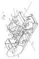
- the carrier 111 includes a chute 113 for receiving an envelope for deposit.
- the chute is mounted to round plates 115 and 117 which are in turn supported on flanged wheels 121 and 123.
- the carrier also has a gate 125 having two parts which are shown in more detail in Figs. 9 and 10.
- the carrier 111 is supported by its wheels 121 and 123 in a rotary support structure comprising circular tracks 131 and 133 which are held apart by spacer bars 135.
- bracket 137 is connected to rings 131 and 133.
- Bracket 137 is connected to connecting rod 139 which acts to tip the support structure about the axis of pin 141.
- Connecting rod 139 is driven by motor 151 through gear train 153 and drive disk 155.
- Fig. 5 the axis of rotation 61 of carrier 111 and the axis of tipping 63 are shown. These axes provide the motion necessary to carry a document between slot 15 and opening 19.
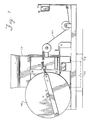
- Fig. 6 a side view of the carrier and its support structure and drive is shown.
- carrier V is shown in position to receive an envelope through opening 19.
- the envelope is received into chute 113 where it is held by gravity while the carrier moves.
- connecting rod 139 tips carrier V cable 161 fastened to the far side of chute 113 pulls downward on the carrier causing it to rotate on its wheels 121, 123 while it is being tipped.
- the downward pull slowly becomes a horizontal pull as cable 161 is guided by pulleys 163 and 165 which are fixed to one of the spacer bars 135.
- Return spring 167 keeps the carrier in tension against the pull of cable 161. After the deposit has been made and disk 155 completes its rotation, return spring 167 restores the carrier 111 to the position shown in Fig. 6.
- FIG. 7 the carrier of Figs. 5 and 6 is shown in the position to release a document which has been rotated and tipped into position to pass through slot 15 in compartment 13.
- Fig. 8 is an end view of the support assembly showing the support ring 133 and flanged wheels 123.
- Support ring 133 has a stop 134 which is engaged by one of the wheels 123 so as to stop rotation of the carrier when it has come into position for alignment with slot 15.
- Fig. 9 shows the chute 113 of the carrier in position over slot 15 just prior to releasing the documents contained therein.
- Fig. 10 shows the same carrier chute 113 after the support assembly has tipped an additional amount so as to cause the arms on gates 125, 126 to release the documents.
- a cash carrier for transporting a bundle of cash which has been issued by an issue mechanism within compartment 13.
- the bundle of cash is accumulated and transported upward out of compartment 13 through slot 15 into the nip of rolls 211, 212, and 213, 214 where it is held.
- Rolls 211 through 214 are part of carrier 221 which is mounted to a bevel gear 225.
- the bevel gear 225 is permanently fixed and a part of carrier 221.
- Carrier 221 and its attached bevel gear 225 are mounted on a spindle passing directly through bevel gear 225 for rotation as bevel gear 225 meshes and moves cross the face of bevel gear 227.
- Bevel gear 227 is likewise fixedly attached to support 229 which is mounted directly to the top wall of compartment 13. Passing through bevel gear 227 is a shaft 231 which is driven by a motor through approximately 90 degrees causing carrier 221 to move from a position in front of slot 15 to a position in front of opening 19. While shaft 231 is driven, bevel gears 225 and 227 interact with each other causing carrier assembly 221 to rotate approximately 90 degrees around the axis 233 so that its side plate 217 which appears in Fig.
- carrier 221 moves with two forms of rotation, a first form of rotation around axis 233 and a second form of rotation around shaft 231 as it is driven by a motor which is not shown.
- carrier 221 moves with two forms of rotation, a first form of rotation around axis 233 and a second form of rotation around shaft 231 as it is driven by a motor which is not shown.
- Each of the details shown in Figs. 5 through 10 may have a counterpart in the embodiment of Figs. 11 and 12 but they have been omitted from these figures in order to avoid duplication.
- the combination of rotation about axis 233 and shaft 231 is depicted schematically by arrow 235.
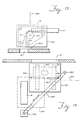
- FIG. 13 another embodiment of the invention in the form of a carrier for moving documents between slot 15 and opening 19 is set forth.
- documents are again collected by a document issuing mechanism and fed upward through slot 15 into the nip between belts 311 and 312. As they are fed between belts 311 and 312, they rotate about roll 315 from a vertical into a horizontal plane. After the documents have been captured between belts 311 and 312, carrier 301 is rotated about pivot 302 into proximity with opening 19. This rotation is better shown in Fig. 14 which is a top view of the carrier 301 shown in position in front of opening 19. Slot 15 is also shown. Carrier 301 is shown in dotted lines over slot 15 whereas it is shown in solid lines in front of opening 19.
- the mechanism for moving carrier 301 includes motor 303 which drives belt 305 around pulley 307.
- Belt 305 has a pin 309 fastened to it. Pin 309 slides in a slot 321 in the top surface of carrier 301.
- motor 303 drives clockwise, the carrier 301 is moved from proximity of slot 15 to its position in front of opening 19. Later motor 303 is driven counterclockwise to return carrier 301 back to its position over slot 15.
- some money 325 is shown in dotted lines ready to be driven out through opening 19.
- carrier 301 causes it to rotate about axis 331 which is the shaft of roll 315 and also causes it to rotate about axis 333 which is the pivot upon which carrier 301 is rotated by motor 303.
- Roll 315 is also driven by motor not shown to move the bank notes or money 325 into and out of carrier 301.
Landscapes
- Business, Economics & Management (AREA)
- Accounting & Taxation (AREA)
- Finance (AREA)
- Physics & Mathematics (AREA)
- General Physics & Mathematics (AREA)
- Financial Or Insurance-Related Operations Such As Payment And Settlement (AREA)
- Pile Receivers (AREA)
- Slot Machines And Peripheral Devices (AREA)
Applications Claiming Priority (2)
| Application Number | Priority Date | Filing Date | Title |
|---|---|---|---|
| US282414 | 1988-12-09 | ||
| US07/282,414 US5020789A (en) | 1988-12-09 | 1988-12-09 | Drive up teller machine |
Publications (3)
| Publication Number | Publication Date |
|---|---|
| EP0372271A2 true EP0372271A2 (fr) | 1990-06-13 |
| EP0372271A3 EP0372271A3 (en) | 1990-11-07 |
| EP0372271B1 EP0372271B1 (fr) | 1994-06-01 |
Family
ID=23081426
Family Applications (1)
| Application Number | Title | Priority Date | Filing Date |
|---|---|---|---|
| EP89121181A Expired - Lifetime EP0372271B1 (fr) | 1988-12-09 | 1989-11-16 | Guichet automatique avec service au volant |
Country Status (5)
| Country | Link |
|---|---|
| US (1) | US5020789A (fr) |
| EP (1) | EP0372271B1 (fr) |
| JP (1) | JPH02195494A (fr) |
| CA (1) | CA2000008C (fr) |
| DE (1) | DE68915711T2 (fr) |
Families Citing this family (6)
| Publication number | Priority date | Publication date | Assignee | Title |
|---|---|---|---|---|
| US6786482B2 (en) | 2001-02-01 | 2004-09-07 | Hallmark Cards Incorporated | Material handler apparatus |
| US7185888B2 (en) * | 2004-03-29 | 2007-03-06 | Palo Alto Research Center Incorporated | Rotational jam clearance apparatus |
| US7512455B2 (en) * | 2004-03-29 | 2009-03-31 | Palo Alto Research Center Incorporated | Method for self-synchronization of modular production systems |
| CN106570982B (zh) * | 2015-10-13 | 2019-07-23 | 武汉理工大学 | 一种基于两个接钞轮的接钞机构 |
| US11276267B2 (en) * | 2019-08-30 | 2022-03-15 | Ncr Corporation | Media rotation mechanism |
| DE102024118225A1 (de) * | 2024-06-27 | 2025-12-31 | Johannes Rudi Pick | Geldterminal und Geldübergabeverfahren |
Family Cites Families (11)
| Publication number | Priority date | Publication date | Assignee | Title |
|---|---|---|---|---|
| US3550811A (en) * | 1967-04-20 | 1970-12-29 | Leonard E Austin | Coin display device |
| US3458056A (en) * | 1968-06-24 | 1969-07-29 | Goodyear Tire & Rubber | Door handling apparatus |
| US3873443A (en) * | 1973-01-03 | 1975-03-25 | Docutel Corp | Depository system |
| US3836980A (en) * | 1973-05-03 | 1974-09-17 | Diebold Inc | Remote depository construction |
| US3897901A (en) * | 1974-06-10 | 1975-08-05 | Diebold Inc | Rotary depository construction |
| JPS55153067A (en) * | 1979-05-15 | 1980-11-28 | Toshiba Corp | Paper currency receiver |
| US4308804A (en) * | 1979-11-08 | 1982-01-05 | Honeywell Information Systems Inc. | Automatic cash depository |
| JPS6260091A (ja) * | 1985-09-10 | 1987-03-16 | 株式会社日立製作所 | 現金自動取引装置 |
| JPS6351228A (ja) * | 1986-08-22 | 1988-03-04 | Hitachi Ltd | リジエクト紙幣処理方式 |
| US4778332A (en) * | 1987-02-09 | 1988-10-18 | The Perkin-Elmer Corporation | Wafer flip apparatus |
| US4753387A (en) * | 1987-07-29 | 1988-06-28 | Lefebure Corporation | Bag depository for drive-up banking and the like |
-
1988
- 1988-12-09 US US07/282,414 patent/US5020789A/en not_active Expired - Lifetime
-
1989
- 1989-09-19 JP JP1240893A patent/JPH02195494A/ja active Granted
- 1989-10-02 CA CA002000008A patent/CA2000008C/fr not_active Expired - Fee Related
- 1989-11-16 EP EP89121181A patent/EP0372271B1/fr not_active Expired - Lifetime
- 1989-11-16 DE DE68915711T patent/DE68915711T2/de not_active Expired - Fee Related
Also Published As
| Publication number | Publication date |
|---|---|
| EP0372271A3 (en) | 1990-11-07 |
| DE68915711D1 (de) | 1994-07-07 |
| CA2000008C (fr) | 1993-09-21 |
| EP0372271B1 (fr) | 1994-06-01 |
| JPH02195494A (ja) | 1990-08-02 |
| DE68915711T2 (de) | 1994-09-15 |
| CA2000008A1 (fr) | 1990-06-09 |
| US5020789A (en) | 1991-06-04 |
| JPH0578075B2 (fr) | 1993-10-28 |
Similar Documents
| Publication | Publication Date | Title |
|---|---|---|
| RU2450359C1 (ru) | Устройство для обработки бумажных листов | |
| JP2002163704A (ja) | 紙幣取扱装置 | |
| KR940007940B1 (ko) | 금융기관 점포시스템과 금융기관 점포시스템의 제어방법 및 지폐류 반송장치 | |
| US4866254A (en) | Automatic bill transaction system | |
| EP0343013B1 (fr) | Systèmes de transfert pneumatique pour de l'argent comptant et cartouches pour utilisation dans de tels systèmes | |
| CN107093261A (zh) | 介质处理装置 | |
| EP0372271B1 (fr) | Guichet automatique avec service au volant | |
| JPS5819984A (ja) | シ−ト状エレメントの分配装置 | |
| CN103258367A (zh) | 介质交易装置 | |
| CN104077835B (zh) | 纸张类处理装置和自动交易装置 | |
| US4728090A (en) | Banknote distributing and dispensing machine | |
| EP1717763B1 (fr) | Appareil obturateur d'une machine d'opérations en espèces | |
| ES2273459T3 (es) | Mecanismo dispensador de hojas. | |
| CN111710090B (zh) | 一种票据处理装置 | |
| CN210895626U (zh) | 一种摩钞机构及高速大额存取款一体机 | |
| CN109949476B (zh) | 一种薄片介质面向整理装置及智能票证处理设备 | |
| JP4838998B2 (ja) | 紙幣入出金機 | |
| CN111009072A (zh) | 一种摩钞机构及高速大额存取款一体机 | |
| JP5790464B2 (ja) | 媒体搬送装置 | |
| JP2863538B2 (ja) | 硬貨搬送装置 | |
| KR19980053115U (ko) | 현금 및 수표 자동지급기용 잼 자동제거장치 | |
| KR20010046612A (ko) | 지폐방출유니트 및 이를 이용한 지폐 자동입출장치 | |
| CN210721630U (zh) | 一种组合联动开启自动取款机出钞口的机构 | |
| JP2723675B2 (ja) | 現金処理装置 | |
| KR200269144Y1 (ko) | 주화 입출금기용 일시 저장장치 |
Legal Events
| Date | Code | Title | Description |
|---|---|---|---|
| PUAI | Public reference made under article 153(3) epc to a published international application that has entered the european phase |
Free format text: ORIGINAL CODE: 0009012 |
|
| AK | Designated contracting states |
Kind code of ref document: A2 Designated state(s): DE FR GB IT |
|
| PUAL | Search report despatched |
Free format text: ORIGINAL CODE: 0009013 |
|
| AK | Designated contracting states |
Kind code of ref document: A3 Designated state(s): DE FR GB IT |
|
| 17P | Request for examination filed |
Effective date: 19901025 |
|
| 17Q | First examination report despatched |
Effective date: 19920929 |
|
| RAP1 | Party data changed (applicant data changed or rights of an application transferred) |
Owner name: INTERBOLD |
|
| GRAA | (expected) grant |
Free format text: ORIGINAL CODE: 0009210 |
|
| AK | Designated contracting states |
Kind code of ref document: B1 Designated state(s): DE FR GB IT |
|
| ITF | It: translation for a ep patent filed | ||
| REF | Corresponds to: |
Ref document number: 68915711 Country of ref document: DE Date of ref document: 19940707 |
|
| ET | Fr: translation filed | ||
| PLBE | No opposition filed within time limit |
Free format text: ORIGINAL CODE: 0009261 |
|
| STAA | Information on the status of an ep patent application or granted ep patent |
Free format text: STATUS: NO OPPOSITION FILED WITHIN TIME LIMIT |
|
| 26N | No opposition filed | ||
| REG | Reference to a national code |
Ref country code: GB Ref legal event code: IF02 |
|
| PGFP | Annual fee paid to national office [announced via postgrant information from national office to epo] |
Ref country code: FR Payment date: 20041010 Year of fee payment: 16 |
|
| PGFP | Annual fee paid to national office [announced via postgrant information from national office to epo] |
Ref country code: GB Payment date: 20041014 Year of fee payment: 16 |
|
| PGFP | Annual fee paid to national office [announced via postgrant information from national office to epo] |
Ref country code: DE Payment date: 20041020 Year of fee payment: 16 |
|
| PG25 | Lapsed in a contracting state [announced via postgrant information from national office to epo] |
Ref country code: IT Free format text: LAPSE BECAUSE OF NON-PAYMENT OF DUE FEES;WARNING: LAPSES OF ITALIAN PATENTS WITH EFFECTIVE DATE BEFORE 2007 MAY HAVE OCCURRED AT ANY TIME BEFORE 2007. THE CORRECT EFFECTIVE DATE MAY BE DIFFERENT FROM THE ONE RECORDED. Effective date: 20051116 Ref country code: GB Free format text: LAPSE BECAUSE OF NON-PAYMENT OF DUE FEES Effective date: 20051116 |
|
| PG25 | Lapsed in a contracting state [announced via postgrant information from national office to epo] |
Ref country code: DE Free format text: LAPSE BECAUSE OF NON-PAYMENT OF DUE FEES Effective date: 20060601 |
|
| GBPC | Gb: european patent ceased through non-payment of renewal fee |
Effective date: 20051116 |
|
| PG25 | Lapsed in a contracting state [announced via postgrant information from national office to epo] |
Ref country code: FR Free format text: LAPSE BECAUSE OF NON-PAYMENT OF DUE FEES Effective date: 20060731 |
|
| REG | Reference to a national code |
Ref country code: FR Ref legal event code: ST Effective date: 20060731 |