EP0372275A2 - Verfahren zum Ändern von Turbinen-Laufräder-Scheiben - Google Patents
Verfahren zum Ändern von Turbinen-Laufräder-Scheiben Download PDFInfo
- Publication number
- EP0372275A2 EP0372275A2 EP89121240A EP89121240A EP0372275A2 EP 0372275 A2 EP0372275 A2 EP 0372275A2 EP 89121240 A EP89121240 A EP 89121240A EP 89121240 A EP89121240 A EP 89121240A EP 0372275 A2 EP0372275 A2 EP 0372275A2
- Authority
- EP
- European Patent Office
- Prior art keywords
- disc
- outline
- original
- modified
- blade
- Prior art date
- Legal status (The legal status is an assumption and is not a legal conclusion. Google has not performed a legal analysis and makes no representation as to the accuracy of the status listed.)
- Withdrawn
Links
Images
Classifications
-
- F—MECHANICAL ENGINEERING; LIGHTING; HEATING; WEAPONS; BLASTING
- F01—MACHINES OR ENGINES IN GENERAL; ENGINE PLANTS IN GENERAL; STEAM ENGINES
- F01D—NON-POSITIVE DISPLACEMENT MACHINES OR ENGINES, e.g. STEAM TURBINES
- F01D5/00—Blades; Blade-carrying members; Heating, heat-insulating, cooling or antivibration means on the blades or the members
-
- B—PERFORMING OPERATIONS; TRANSPORTING
- B23—MACHINE TOOLS; METAL-WORKING NOT OTHERWISE PROVIDED FOR
- B23P—METAL-WORKING NOT OTHERWISE PROVIDED FOR; COMBINED OPERATIONS; UNIVERSAL MACHINE TOOLS
- B23P6/00—Restoring or reconditioning objects
- B23P6/002—Repairing turbine components, e.g. moving or stationary blades, rotors
- B23P6/007—Repairing turbine components, e.g. moving or stationary blades, rotors using only additive methods, e.g. build-up welding
-
- B—PERFORMING OPERATIONS; TRANSPORTING
- B23—MACHINE TOOLS; METAL-WORKING NOT OTHERWISE PROVIDED FOR
- B23K—SOLDERING OR UNSOLDERING; WELDING; CLADDING OR PLATING BY SOLDERING OR WELDING; CUTTING BY APPLYING HEAT LOCALLY, e.g. FLAME CUTTING; WORKING BY LASER BEAM
- B23K9/00—Arc welding or cutting
- B23K9/04—Welding for other purposes than joining, e.g. built-up welding
- B23K9/044—Built-up welding on three-dimensional surfaces
- B23K9/046—Built-up welding on three-dimensional surfaces on surfaces of revolution
-
- B—PERFORMING OPERATIONS; TRANSPORTING
- B23—MACHINE TOOLS; METAL-WORKING NOT OTHERWISE PROVIDED FOR
- B23P—METAL-WORKING NOT OTHERWISE PROVIDED FOR; COMBINED OPERATIONS; UNIVERSAL MACHINE TOOLS
- B23P15/00—Making specific metal objects by operations not covered by a single other subclass or a group in this subclass
- B23P15/006—Making specific metal objects by operations not covered by a single other subclass or a group in this subclass turbine wheels
-
- F—MECHANICAL ENGINEERING; LIGHTING; HEATING; WEAPONS; BLASTING
- F01—MACHINES OR ENGINES IN GENERAL; ENGINE PLANTS IN GENERAL; STEAM ENGINES
- F01D—NON-POSITIVE DISPLACEMENT MACHINES OR ENGINES, e.g. STEAM TURBINES
- F01D5/00—Blades; Blade-carrying members; Heating, heat-insulating, cooling or antivibration means on the blades or the members
- F01D5/005—Repairing methods or devices
-
- Y—GENERAL TAGGING OF NEW TECHNOLOGICAL DEVELOPMENTS; GENERAL TAGGING OF CROSS-SECTIONAL TECHNOLOGIES SPANNING OVER SEVERAL SECTIONS OF THE IPC; TECHNICAL SUBJECTS COVERED BY FORMER USPC CROSS-REFERENCE ART COLLECTIONS [XRACs] AND DIGESTS
- Y10—TECHNICAL SUBJECTS COVERED BY FORMER USPC
- Y10T—TECHNICAL SUBJECTS COVERED BY FORMER US CLASSIFICATION
- Y10T29/00—Metal working
- Y10T29/49—Method of mechanical manufacture
- Y10T29/49316—Impeller making
- Y10T29/49318—Repairing or disassembling
-
- Y—GENERAL TAGGING OF NEW TECHNOLOGICAL DEVELOPMENTS; GENERAL TAGGING OF CROSS-SECTIONAL TECHNOLOGIES SPANNING OVER SEVERAL SECTIONS OF THE IPC; TECHNICAL SUBJECTS COVERED BY FORMER USPC CROSS-REFERENCE ART COLLECTIONS [XRACs] AND DIGESTS
- Y10—TECHNICAL SUBJECTS COVERED BY FORMER USPC
- Y10T—TECHNICAL SUBJECTS COVERED BY FORMER US CLASSIFICATION
- Y10T29/00—Metal working
- Y10T29/49—Method of mechanical manufacture
- Y10T29/49316—Impeller making
- Y10T29/4932—Turbomachine making
-
- Y—GENERAL TAGGING OF NEW TECHNOLOGICAL DEVELOPMENTS; GENERAL TAGGING OF CROSS-SECTIONAL TECHNOLOGIES SPANNING OVER SEVERAL SECTIONS OF THE IPC; TECHNICAL SUBJECTS COVERED BY FORMER USPC CROSS-REFERENCE ART COLLECTIONS [XRACs] AND DIGESTS
- Y10—TECHNICAL SUBJECTS COVERED BY FORMER USPC
- Y10T—TECHNICAL SUBJECTS COVERED BY FORMER US CLASSIFICATION
- Y10T29/00—Metal working
- Y10T29/49—Method of mechanical manufacture
- Y10T29/49718—Repairing
- Y10T29/49732—Repairing by attaching repair preform, e.g., remaking, restoring, or patching
- Y10T29/49734—Repairing by attaching repair preform, e.g., remaking, restoring, or patching and removing damaged material
- Y10T29/49737—Metallurgically attaching preform
-
- Y—GENERAL TAGGING OF NEW TECHNOLOGICAL DEVELOPMENTS; GENERAL TAGGING OF CROSS-SECTIONAL TECHNOLOGIES SPANNING OVER SEVERAL SECTIONS OF THE IPC; TECHNICAL SUBJECTS COVERED BY FORMER USPC CROSS-REFERENCE ART COLLECTIONS [XRACs] AND DIGESTS
- Y10—TECHNICAL SUBJECTS COVERED BY FORMER USPC
- Y10T—TECHNICAL SUBJECTS COVERED BY FORMER US CLASSIFICATION
- Y10T29/00—Metal working
- Y10T29/49—Method of mechanical manufacture
- Y10T29/4998—Combined manufacture including applying or shaping of fluent material
- Y10T29/49982—Coating
- Y10T29/49986—Subsequent to metal working
Definitions
- the present invention relates to turbine rotors having integral blade-supporting discs, and particularly to a method for modifying such discs to accommodate a replacement turbine blade requiring a disc having a wider blade supporting area than that required by the original blade.
- Certain turbines which are already in service are constructed to have blade supporting discs which are integral with the turbine rotor.
- problems have been encountered with respect to the fastening of some of the blades to their associated discs.
- One solution to these problems is to replace an existing blade with a new blade which is wider and stronger than the original blade and which requires a disc having a wider blade supporting region.
- the necessary modification could be made by cutting off the existing disc as close as possible to its inner extremity and then welding on a new disc.
- This procedure would be extremely complicated because the disc must be manufactured in two halves in order to be placed around the rotor, and then must be welded to the rotor at a relatively inaccessible location.
- a second possibility would involve cutting off the affected rotor end and then welding a new forging in place of the removed portion. This procedure is disadvantageous because such a new forging would be very expensive, given that it would probably include other rows of discs which must be machined and rebladed, certain delays would be encountered in obtaining the new forging, and costly accessory equipment must be obtained for positioning the forging relative the remainder of the rotor during welding.
- the present invention resides in a method for modifying an original blade supporting disc which is integral with a turbine rotor, and which has an original outline, in order to create a modified disc which has an outline different from the original outline and which provides a blade-supporting region of increased size, the original disc having at least one portion which protrudes beyond the outline of the modified disc characterized in that each portion of the original disc which protrudes beyond the outline of the modified disc is machined away, the original disc is built up with weld metal past the outline of the modified disc at all locations where the outline of the original disc, after said machining step, is enclosed by the outline of said modified disc; and the excess parts of the weld metal are then machined away to provide the outline of the modified disc.
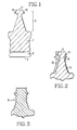
- Figure 1 shows a portion of a turbine rotor 2 having a central axis 4, about which the rotor is mounted to rotate, and having an axial bore 6 concentric with axis 4.
- Rotor 2 is provided, at its periphery, with an integral blade-supporting disc 8 having seal-supporting flanges 10 and a blade-supporting base 11..
- Disc 8 is constructed to be connected to the root of a selected turbine blade and is one of several discs distributed axially along rotor 2.
- the desired modification is made simply by machining away relatively small portions of disc 8, building up added portions, by suitable welding procedures, to provide the material needed for the modified disc, and then machining the built-up portions to arrive at the final configuration of the modified disc.
- This process can be easily carried out in such a manner as to shift the central plane of the disc, which plane is perpendicular to axis 4, in order to provide added spacing at the entrance side or the exit side of the associated blading.
- This is advantageous because it provides, for example, an increased rotor space between the new, larger blade and the blade upstream or downstream thereof.
- Figure 2 illustrates the manner in which a disc is modified according to the present invention.
- the original disc is constituted by portions 12, 14 and 16, all forging an integral part of the rotor body.
- portions 14 and 16 are machined away and then portions 18 and 20 are added by build-up of weld metal, followed by machining to arrive at the desired final configuration represented in Figure 2 by portions 12, 18 and 20.
- portion 12 is built up by a welding procedure to initially give disc 8 the form shown by the solid line outline in Figure 3. Then, by machining operations, excess metal is cut away to give disc 8 the final, modified form, the outline of which is illustrated by broken lines in Figure 3.
- weld metal can be effected in a variety of ways. Firstly, the large volume portions, except for the outer surface of the resulting disc which is exposed to higher service stresses and a hostile environment, should preferably be deposited by a submerged arc or gas metal arc weld process. Both of these processes are characterized by relatively high deposition rates. Then, the regions which will constitute the exposed surfaces of the modified disc are preferably built up by a gas tungsten arc weld process which, although being relatively slow, produces a weld having exceptionally good mechanically properties.
- the rotor During performance of the submerged arc or gas metal arc weld process, the rotor must be positioned so that its axis is oriented vertically.
- the entire weld build up can be effected by the gas tungsten arc weld process.
- this process is employed, not only does the entire weld have exceptionally good mechanical properties, but it is not necessary to move the rotor to bring its axis to a vertical orientation.
- a disc 8 which originally supported a blade having a root width of the order of 10 cm can be modified to support a blade having a root width of the order of 14 cm.
Landscapes
- Engineering & Computer Science (AREA)
- Mechanical Engineering (AREA)
- General Engineering & Computer Science (AREA)
- Physics & Mathematics (AREA)
- Plasma & Fusion (AREA)
- Turbine Rotor Nozzle Sealing (AREA)
- Butt Welding And Welding Of Specific Article (AREA)
- Breeding Of Plants And Reproduction By Means Of Culturing (AREA)
Applications Claiming Priority (2)
| Application Number | Priority Date | Filing Date | Title |
|---|---|---|---|
| US281136 | 1988-12-08 | ||
| US07/281,136 US4893388A (en) | 1988-12-08 | 1988-12-08 | Method of modifying turbine rotor discs |
Publications (2)
| Publication Number | Publication Date |
|---|---|
| EP0372275A2 true EP0372275A2 (de) | 1990-06-13 |
| EP0372275A3 EP0372275A3 (de) | 1990-09-26 |
Family
ID=23076093
Family Applications (1)
| Application Number | Title | Priority Date | Filing Date |
|---|---|---|---|
| EP19890121240 Withdrawn EP0372275A3 (de) | 1988-12-08 | 1989-11-16 | Verfahren zum Ändern von Turbinen-Laufräder-Scheiben |
Country Status (6)
| Country | Link |
|---|---|
| US (1) | US4893388A (de) |
| EP (1) | EP0372275A3 (de) |
| JP (1) | JP2876561B2 (de) |
| KR (1) | KR0157043B1 (de) |
| CN (1) | CN1043770A (de) |
| CA (1) | CA2004851A1 (de) |
Families Citing this family (23)
| Publication number | Priority date | Publication date | Assignee | Title |
|---|---|---|---|---|
| US5085363A (en) * | 1990-11-01 | 1992-02-04 | Westinghouse Electric Corp. | Method of weld repairing of a section of a metallic cylindrical member |
| US5113582A (en) * | 1990-11-13 | 1992-05-19 | General Electric Company | Method for making a gas turbine engine component |
| US5172475A (en) * | 1991-12-02 | 1992-12-22 | Westinghouse Electric Corp. | Method for repairing a rotor |
| US5269057A (en) * | 1991-12-24 | 1993-12-14 | Freedom Forge Corporation | Method of making replacement airfoil components |
| US5283418A (en) * | 1992-02-27 | 1994-02-01 | Westinghouse Electric Corp. | Automated rotor welding processes using neural networks |
| DE4225443C2 (de) * | 1992-07-31 | 1995-11-16 | Mtu Muenchen Gmbh | Verfahren zur Herstellung einer Schweißverbindung von Bauteilen für Turbomaschinen, insbesondere zur Bauteilreperatur und Verwendung des Verfahrens |
| US5285572A (en) * | 1992-08-12 | 1994-02-15 | General Electric Company | Method and system for machining contoured parts |
| DE4239710A1 (de) * | 1992-11-26 | 1994-06-01 | Abb Patent Gmbh | Läufer einer Turbine |
| US5591363A (en) * | 1995-03-02 | 1997-01-07 | Westinghouse Electric Corporation | Optimized welding technique for NiMoV rotors for high temperature applications |
| US5606797A (en) * | 1995-06-26 | 1997-03-04 | Reynolds; Russell B. | Process to restore and refurbish turbocharger housing |
| US5746579A (en) * | 1996-12-27 | 1998-05-05 | Westinghouse Electric Corporation | Stress corrosion resistant rims and discs for steam turbine rotors device and method |
| US5794338A (en) * | 1997-04-04 | 1998-08-18 | General Electric Company | Method for repairing a turbine engine member damaged tip |
| US5883456A (en) * | 1997-10-20 | 1999-03-16 | Siemens Westinghouse Power Corporation | Generator rotor and method for eliminating keyway stress cracks in same |
| US6168382B1 (en) * | 1998-10-20 | 2001-01-02 | General Electric Co. | Turbine rotor wheel with forged replacement dovetail and method of repair |
| JP3473549B2 (ja) * | 2000-04-28 | 2003-12-08 | 松下電器産業株式会社 | 送風機羽根車とその送風機羽根車を備えた空気調和機 |
| GB0107559D0 (en) * | 2001-03-27 | 2001-05-16 | Rolls Royce Plc | Apparatus and method for forming a body |
| US6571472B2 (en) | 2001-08-14 | 2003-06-03 | General Electric Company | Restoration of thickness to load-bearing gas turbine engine components |
| DE10328310A1 (de) † | 2003-06-23 | 2005-01-13 | Alstom Technology Ltd | Verfahren zum Modifizieren der Kopplungsgeometrie bei Deckbandsegmenten von Turbinenlaufschaufeln |
| US8266800B2 (en) * | 2003-09-10 | 2012-09-18 | Siemens Energy, Inc. | Repair of nickel-based alloy turbine disk |
| WO2011102945A2 (en) * | 2010-02-19 | 2011-08-25 | Dresser-Rand Company | Welded structural flats on cases to eliminate nozzles |
| US8595930B2 (en) * | 2010-03-24 | 2013-12-03 | Dresser-Rand Company | Press-fitting corrosion resistant liners in nozzles and casings |
| JP5936530B2 (ja) * | 2012-12-19 | 2016-06-22 | 三菱日立パワーシステムズ株式会社 | タービンの動翼の製造方法 |
| US20150231690A1 (en) * | 2014-02-17 | 2015-08-20 | Siemens Aktiengesellschaft | Method for producing a turbine rotor |
Family Cites Families (16)
| Publication number | Priority date | Publication date | Assignee | Title |
|---|---|---|---|---|
| US4028787A (en) * | 1975-09-15 | 1977-06-14 | Cretella Salvatore | Refurbished turbine vanes and method of refurbishment thereof |
| US4050133A (en) * | 1976-06-07 | 1977-09-27 | Cretella Salvatore | Method of refurbishing turbine vanes and the like |
| US4128929A (en) * | 1977-03-15 | 1978-12-12 | Demusis Ralph T | Method of restoring worn turbine components |
| US4098450A (en) * | 1977-03-17 | 1978-07-04 | General Electric Company | Superalloy article cleaning and repair method |
| US4291448A (en) * | 1977-12-12 | 1981-09-29 | Turbine Components Corporation | Method of restoring the shrouds of turbine blades |
| GB2091140B (en) * | 1981-01-15 | 1984-04-18 | Refurbished Turbine Components | Turbine baldes repair |
| JPS58178804A (ja) * | 1982-04-14 | 1983-10-19 | Hitachi Ltd | 蒸気タ−ビンロ−タシヤフト |
| US4611744A (en) * | 1982-06-23 | 1986-09-16 | Refurbished Turbine Components Ltd. | Turbine blade repair |
| DE3235310C2 (de) * | 1982-09-24 | 1985-08-22 | Klein, Schanzlin & Becker Ag, 6710 Frankenthal | Verfahren zur Herstellung eines an seinen Kanten gepanzerten Werkstückes |
| JPS5956526A (ja) * | 1982-09-25 | 1984-04-02 | Toshiba Corp | タ−ビンロ−タの残留応力除去方法 |
| DE3430114C2 (de) * | 1984-08-16 | 1986-12-18 | J.M. Voith Gmbh, 7920 Heidenheim | Vorrichtung zum Aufbauen eines Werkstücks durch Auftragschweißen |
| US4743733A (en) * | 1984-10-01 | 1988-05-10 | General Electric Company | Method and apparatus for repairing metal in an article |
| DE3521664A1 (de) * | 1985-06-18 | 1986-12-18 | BBC Aktiengesellschaft Brown, Boveri & Cie., Baden, Aargau | Verfahren zur befestigung von schaufeln auf dem umfang des rotorkoerpers einer dampfturbine |
| US4633554A (en) * | 1985-08-08 | 1987-01-06 | Westinghouse Electric Corp. | Method for repairing a steam turbine or generator rotor |
| US4726101A (en) * | 1986-09-25 | 1988-02-23 | United Technologies Corporation | Turbine vane nozzle reclassification |
| US4883216A (en) * | 1988-03-28 | 1989-11-28 | General Electric Company | Method for bonding an article projection |
-
1988
- 1988-12-08 US US07/281,136 patent/US4893388A/en not_active Expired - Lifetime
-
1989
- 1989-11-16 EP EP19890121240 patent/EP0372275A3/de not_active Withdrawn
- 1989-12-07 KR KR1019890018132A patent/KR0157043B1/ko not_active Expired - Lifetime
- 1989-12-07 CA CA002004851A patent/CA2004851A1/en not_active Abandoned
- 1989-12-08 CN CN89109120A patent/CN1043770A/zh active Pending
- 1989-12-08 JP JP1320353A patent/JP2876561B2/ja not_active Expired - Lifetime
Also Published As
| Publication number | Publication date |
|---|---|
| US4893388A (en) | 1990-01-16 |
| EP0372275A3 (de) | 1990-09-26 |
| KR900010190A (ko) | 1990-07-06 |
| JP2876561B2 (ja) | 1999-03-31 |
| KR0157043B1 (ko) | 1998-11-16 |
| JPH02196102A (ja) | 1990-08-02 |
| CA2004851A1 (en) | 1990-06-08 |
| CN1043770A (zh) | 1990-07-11 |
Similar Documents
| Publication | Publication Date | Title |
|---|---|---|
| EP0372275A2 (de) | Verfahren zum Ändern von Turbinen-Laufräder-Scheiben | |
| US10502064B2 (en) | Power beam welded cavity-back titanium hollow fan blade | |
| US6494677B1 (en) | Turbine nozzle segment and method of repairing same | |
| CA1233124A (en) | Steam turbine diaphragm | |
| US5269057A (en) | Method of making replacement airfoil components | |
| US5060842A (en) | Method for refurbishing nozzle block vanes of a steam turbine | |
| EP0184934B1 (de) | Turbinenräder aus zwei Legierungen und Verfahren zu ihrer Herstellung | |
| US3802046A (en) | Method of making or reconditioning a turbine-nozzle or the like assembly | |
| US6568077B1 (en) | Blisk weld repair | |
| US3199836A (en) | Axial flow turbo-machine blade with abrasive tip | |
| US4464094A (en) | Turbine engine component and method of making the same | |
| US5746579A (en) | Stress corrosion resistant rims and discs for steam turbine rotors device and method | |
| US6520836B2 (en) | Method of forming a trailing edge cutback for a turbine bucket | |
| EP1674665B1 (de) | Turbinenleitschaufelsegment und Reparaturmethode dafür | |
| KR20090023291A (ko) | 터빈 로터 장치 및 시스템 | |
| EP1319802A2 (de) | Turbinenleitapparat und Methode, um diesen zu reparieren | |
| KR20220085762A (ko) | 블레이드형 로터의 조합 적층 및 절삭 제조 | |
| EP1564371B1 (de) | Reparaturverfahren einen Fuß aus einem gegossenen Statorschaufelsegmente | |
| EP0408531B1 (de) | Verfahren zur Herstellung eines geteilten kreisförmigen Ringes | |
| JPH11324607A (ja) | ガスタ―ビン、特に航空エンジン用の組み立て式ノズルリングとその製作方法 | |
| US20140056716A1 (en) | Bicast turbine engine components | |
| US5772401A (en) | Diaphragm construction for turbomachinery | |
| EP1050664B1 (de) | Nabe-Achse Verbindung | |
| EP1959095A2 (de) | Dimensionale Wiederherstellung von Statorkopfplatten | |
| JPH0676763B2 (ja) | タ−ビン静翼の栓溶接方法 |
Legal Events
| Date | Code | Title | Description |
|---|---|---|---|
| PUAI | Public reference made under article 153(3) epc to a published international application that has entered the european phase |
Free format text: ORIGINAL CODE: 0009012 |
|
| AK | Designated contracting states |
Kind code of ref document: A2 Designated state(s): CH DE ES GB IT LI SE |
|
| PUAL | Search report despatched |
Free format text: ORIGINAL CODE: 0009013 |
|
| AK | Designated contracting states |
Kind code of ref document: A3 Designated state(s): CH DE ES GB IT LI SE |
|
| 17P | Request for examination filed |
Effective date: 19901228 |
|
| 17Q | First examination report despatched |
Effective date: 19910729 |
|
| STAA | Information on the status of an ep patent application or granted ep patent |
Free format text: STATUS: THE APPLICATION IS DEEMED TO BE WITHDRAWN |
|
| 18D | Application deemed to be withdrawn |
Effective date: 19911205 |