EP0372376A2 - Mécanisme d'entraînement oscillant - Google Patents
Mécanisme d'entraînement oscillant Download PDFInfo
- Publication number
- EP0372376A2 EP0372376A2 EP89122051A EP89122051A EP0372376A2 EP 0372376 A2 EP0372376 A2 EP 0372376A2 EP 89122051 A EP89122051 A EP 89122051A EP 89122051 A EP89122051 A EP 89122051A EP 0372376 A2 EP0372376 A2 EP 0372376A2
- Authority
- EP
- European Patent Office
- Prior art keywords
- drive shaft
- axis
- oscillating
- drive according
- oscillating drive
- Prior art date
- Legal status (The legal status is an assumption and is not a legal conclusion. Google has not performed a legal analysis and makes no representation as to the accuracy of the status listed.)
- Granted
Links
- 230000010355 oscillation Effects 0.000 claims description 21
- 239000000463 material Substances 0.000 claims description 4
- 229910000639 Spring steel Inorganic materials 0.000 claims description 2
- 239000000243 solution Substances 0.000 description 19
- 238000005096 rolling process Methods 0.000 description 13
- 238000004519 manufacturing process Methods 0.000 description 6
- 238000005520 cutting process Methods 0.000 description 3
- 230000005540 biological transmission Effects 0.000 description 2
- 239000011248 coating agent Substances 0.000 description 2
- 238000000576 coating method Methods 0.000 description 2
- 239000004809 Teflon Substances 0.000 description 1
- 229920006362 Teflon® Polymers 0.000 description 1
- 238000010276 construction Methods 0.000 description 1
- 230000007423 decrease Effects 0.000 description 1
- 230000003247 decreasing effect Effects 0.000 description 1
- 238000006073 displacement reaction Methods 0.000 description 1
- 230000000284 resting effect Effects 0.000 description 1
- 239000012791 sliding layer Substances 0.000 description 1
- 239000007787 solid Substances 0.000 description 1
- 238000003860 storage Methods 0.000 description 1
- 230000001960 triggered effect Effects 0.000 description 1
Images


Classifications
-
- F—MECHANICAL ENGINEERING; LIGHTING; HEATING; WEAPONS; BLASTING
- F16—ENGINEERING ELEMENTS AND UNITS; GENERAL MEASURES FOR PRODUCING AND MAINTAINING EFFECTIVE FUNCTIONING OF MACHINES OR INSTALLATIONS; THERMAL INSULATION IN GENERAL
- F16H—GEARING
- F16H21/00—Gearings comprising primarily only links or levers, with or without slides
- F16H21/10—Gearings comprising primarily only links or levers, with or without slides all movement being in, or parallel to, a single plane
- F16H21/40—Gearings comprising primarily only links or levers, with or without slides all movement being in, or parallel to, a single plane for interconverting rotary motion and oscillating motion
-
- B—PERFORMING OPERATIONS; TRANSPORTING
- B24—GRINDING; POLISHING
- B24B—MACHINES, DEVICES, OR PROCESSES FOR GRINDING OR POLISHING; DRESSING OR CONDITIONING OF ABRADING SURFACES; FEEDING OF GRINDING, POLISHING, OR LAPPING AGENTS
- B24B41/00—Component parts such as frames, beds, carriages, headstocks
- B24B41/04—Headstocks; Working-spindles; Features relating thereto
-
- B—PERFORMING OPERATIONS; TRANSPORTING
- B23—MACHINE TOOLS; METAL-WORKING NOT OTHERWISE PROVIDED FOR
- B23Q—DETAILS, COMPONENTS, OR ACCESSORIES FOR MACHINE TOOLS, e.g. ARRANGEMENTS FOR COPYING OR CONTROLLING; MACHINE TOOLS IN GENERAL CHARACTERISED BY THE CONSTRUCTION OF PARTICULAR DETAILS OR COMPONENTS; COMBINATIONS OR ASSOCIATIONS OF METAL-WORKING MACHINES, NOT DIRECTED TO A PARTICULAR RESULT
- B23Q5/00—Driving or feeding mechanisms; Control arrangements therefor
- B23Q5/02—Driving main working members
- B23Q5/027—Driving main working members reciprocating members
-
- B—PERFORMING OPERATIONS; TRANSPORTING
- B24—GRINDING; POLISHING
- B24B—MACHINES, DEVICES, OR PROCESSES FOR GRINDING OR POLISHING; DRESSING OR CONDITIONING OF ABRADING SURFACES; FEEDING OF GRINDING, POLISHING, OR LAPPING AGENTS
- B24B1/00—Processes of grinding or polishing; Use of auxiliary equipment in connection with such processes
- B24B1/04—Processes of grinding or polishing; Use of auxiliary equipment in connection with such processes subjecting the grinding or polishing tools, the abrading or polishing medium or work to vibration, e.g. grinding with ultrasonic frequency
-
- B—PERFORMING OPERATIONS; TRANSPORTING
- B24—GRINDING; POLISHING
- B24B—MACHINES, DEVICES, OR PROCESSES FOR GRINDING OR POLISHING; DRESSING OR CONDITIONING OF ABRADING SURFACES; FEEDING OF GRINDING, POLISHING, OR LAPPING AGENTS
- B24B23/00—Portable grinding machines, e.g. hand-guided; Accessories therefor
- B24B23/04—Portable grinding machines, e.g. hand-guided; Accessories therefor with oscillating grinding tools; Accessories therefor
-
- B—PERFORMING OPERATIONS; TRANSPORTING
- B26—HAND CUTTING TOOLS; CUTTING; SEVERING
- B26B—HAND-HELD CUTTING TOOLS NOT OTHERWISE PROVIDED FOR
- B26B7/00—Hand knives with reciprocating motor-driven blades
Definitions
- the invention relates to an oscillation drive for tools with a drive shaft driven by a motor, with an oscillation drive element seated on the drive shaft, with a tool drive shaft aligned with its axis transverse to the drive shaft and with a pivoting element extending from the tool drive shaft in the direction of the oscillation drive element.
- Such an oscillation drive is known from German utility model G 80 31 084.5.
- This oscillation drive is constructed in such a way that the swivel element forms a rocker arm in which a piston is displaceable parallel to the axis of the tool drive shaft and can also be rotated about its displacement axis.
- This piston is penetrated by an eccentric pin and is also slidably mounted on the eccentric pin in the longitudinal direction.
- the invention is therefore based on the object of improving an oscillation drive of the generic type in such a way that it is less expensive and easier to manufacture.
- oscillation drive element has an eccentric element which is connected to the pivot element via a connecting element comprising a rotary bearing combined with a tilting joint which can be tilted on all sides with respect to an axis of rotation, and in that on the Connecting part of the swivel element with a directional component lying in a plane passing through the axis of the tool drive shaft, is otherwise rigidly connected to the tool drive shaft.
- the advantage of the solution according to the invention can be seen in the fact that the solution according to the invention is easier to manufacture and that, in particular, larger torques can also be transmitted in a simpler manner.
- the solution according to the invention can be designed so that it is smaller than the previously known solution.
- the part of the swivel element which engages the connecting element can only be swiveled in the plane passing through the tool drive shaft.
- the tilt joint has tilt axes which lie essentially in one plane. In particular, there are no different geometrical relationships when tilting about one or the other tilt axis.
- the solution according to the invention can be built particularly compactly if the plane in which the tilt axes of the tilt joint lie coincides with a bearing plane of the pivot bearing, so that the individual components do not have to be arranged in succession.
- the oscillation drive according to the invention is intended to work in particular at high speeds and small swivel angles in the oscillating movements, it is also not necessary to make the tilt joint tiltable by a large angle, so that advantageously the tilt joint only has a tilt angle range of a maximum of 10 °, advantageously a maximum of 5 ° , or less.
- a particularly simple form of realizing the connecting link according to the invention is when the connecting link is a self-aligning bearing, since the self-aligning bearing forms a pivot bearing on the one hand and a tilt joint that can be tilted about two mutually perpendicular tilt axes.
- the swivel axis intersects the axis of the tool drive shaft.
- the part of the swivel element engaging the connecting element for example its end cooperating with the connecting element, moves on a circular path which represents a section of a spherical surface with a plane, the center of the spherical surface being the intersection of the pivot axis is the axis of the tool drive shaft.
- the connecting element can in principle be held both on the swivel element and on the eccentric element.
- the connecting member is held on the eccentric element so that it can then be balanced in a simple manner and the entire mass of the connecting member cannot contribute to vibrations of the oscillation drive.
- a structurally particularly advantageous embodiment provides that the eccentric element is a wheel, which can then have a correspondingly eccentrically arranged bore as a recess for the connecting member.
- the construction is advantageously chosen so that the pivoting element engages with a pin in a receptacle of the connecting element, so that there are advantages in the assembly of the oscillation drive according to the invention, since the pivoting element only must be inserted into the recording.
- the swivel element is immovably connected to the tool drive shaft and that the swivel element is at least partially made in the plane passing through the axis of the tool drive shaft is elastically movable material. This saves a joint through this design of the swivel element.
- the simplest way of designing the swivel element in this way is that it comprises a spring steel plate, in which in particular the narrow side thereof runs parallel to the plane passing through the axis of the tool drive shaft and the broad side of which is perpendicular to this plane.
- the pivoting element is advantageously designed such that it engages around the tool drive shaft in a fork-shaped manner.
- the pivoting element has a carrier on which the part of the connecting element engaging it is movably guided in the plane passing through the axis of the tool drive shaft, which has the advantage that not all of it Torque must be transmitted via the attachment or the bearing of the swivel element on the tool shaft.
- An advantageous embodiment provides that the part of the swivel element engaging on the connecting member engages around the fingers on both sides, so that a torque transmission to both sides is possible.
- the finger is preferably designed such that it has guide surfaces parallel to this plane, on which the part of the swivel element engaging the connecting member is guided.
- sliding elements are preferably sliding layers or can also comprise rolling elements.
- the oscillation drive element is a wobble element which comprises a first wobble element which is seated on the drive shaft and rotates with it and a second wobble element which is moved by the first wobble element but does not rotate with it. and that the pivot element on the second wobble member is pivotally movable about an axis.
- the wobble element is a wobble bearing with a bearing inner ring forming the first wobble member and a bearing outer ring forming the second wobble member.
- the swash bearing is preferably designed as a roller bearing.
- the bearing outer ring is rotatably mounted on the pivot element about a pivot axis.
- the swivel element preferably has a fork which engages around the bearing outer ring and carries the bearing elements forming the swivel axis.
- the wobble element is aligned with respect to the drive shaft axis in such a way that it encloses an angle between 85 and 90 ° with the drive shaft axis, so that the swivel angle obtainable with the oscillation drive is in the range of ⁇ 10 ° and> 0 °.
- a second variant of the second concept according to the invention provides that the bearing outer ring has a rod which extends essentially in the radial direction through a longitudinal and rotary guide on the swivel element and that the axis of the tool drive shaft runs laterally next to the drive shaft axis and thus does not intersect it .
- the rod triggered by the wobbling movements of the outer bearing ring, performs rotational movements around the axis of the tool drive shaft as the axis of rotation.
- the guiding of the rod in the swivel element is most conveniently carried out in that the rod is held in the longitudinal and rotary guide by a sliding element.
- the sliding element can expediently be designed as a sliding coating. However, there are lower frictional resistances if the sliding element comprises rolling elements.
- the bearing inner ring is held on the drive shaft in a rotationally fixed but displaceable manner in the direction of the drive shaft axis.
- the bearing inner ring is held in a rotationally fixed manner on the drive shaft by means of splines.
- a guide direction of the longitudinal and rotary guide intersects the drive shaft axis. This can be realized most advantageously in that the guide direction is perpendicular to the axis of the tool drive shaft axis.
- a third variant in the context of the second concept of the solution according to the invention provides that the wobble element has a wobble plate as the first wobble member and a pressure disk acted upon by the wobble plate in the direction parallel to the drive shaft axis as the second wobble member.
- This solution has the advantage that it is very easy to manufacture.
- the swashplate can either be a disk that is inclined to the drive shaft axis or a disk with a front surface that runs parallel to a plane perpendicular to the drive shaft axis in the radial direction of the drive shaft axis, but with increasing and increasing in the course of a revolution from a minimum distance to a maximum distance again decreasing distances from this level to the minimum distance.
- the pressure plate now performs the same wobble movements as the swash plate.
- the thrust washer acts on the pivoting element along a contact line and can thus tilt about this contact line.
- This line of equipment is expediently aligned so that it intersects the drive shaft axis.
- the swivel part is designed so that it has an edge forming the contact line.
- the pressure plate is to be movable with respect to the swivel part, in particular also in the direction of the contact line, the pressure plate must be kept separate. It is therefore advantageously provided that the thrust washer is rotatably held by the drive shaft and on it, so that the thrust washer does not rotate with the drive shaft, but remains standing, but can be tilted with respect to the drive shaft.
- a sliding element is expediently provided between the swash plate and the pressure plate.
- this sliding element can be a sliding coating, but it is even better if the sliding element comprises rolling elements.
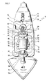
- a first variant, designated as a whole in FIG. 1 by 10, of a first concept of an oscillation drive according to the invention comprises a motor, designated as a whole as 12, which, as shown in FIGS. 2 and 3, drives a drive shaft 14 which has an eccentric wheel on its front end 16 wears.
- This eccentric wheel 16 is arranged coaxially with a drive shaft axis 18 and has a circular cylindrical recess 20, which is offset eccentrically with respect to the drive shaft axis 18 and whose axis 22 is aligned parallel to the drive shaft axis 18.
- a self-aligning bearing 24 is inserted, which has a bearing outer ring 26, the inner ring surfaces 28 are shaped in the manner of an annular cutout from a hollow ball, so that rolling elements 30 running on this ring surface, which in turn are located on a bearing inner ring 32 in support its outer casing incorporated guide grooves 34, a total tilting of the bearing inner ring 32 relative to the axis 22 allows a spherical center of the hollow spherical inner ring surface 28 of the bearing outer ring 26, which lies on the axis 22.
- a tilt angle, based on the axis 22, is preferably in the range of ⁇ 5 °, which results in a maximum tilt range of ⁇ 10 °.
- the center of the sphere of the inner ring surface 28 lies at the intersection of a bearing plane 36 which is perpendicular to the axis 22 and forms a plane of symmetry of the self-aligning bearing 24 with the axis 22, so that the two tilting axes about which the bearing inner ring 32 can be tilted relative to the bearing outer ring 26 in the storage level 36 lie.
- the bearing inner ring 32 has a receiving bore 38 which is coaxial with the axis 22 in its non-tilted position.
- a pin 40 of an arm 42 engages in this and transmits the movements of the receiving bore eccentric to the drive shaft axis 18 to a tool drive shaft 44.
- the tool drive shaft 44 is mounted twice in a gear housing 46 enclosing the eccentric wheel 16, the arm 42 and an upper section 48, namely in the region of a lower part 50 and in the region of an upper part 52 of the transmission housing 46.
- a lower section 54 of the tool drive shaft 44 extends beyond the gear housing 46 and carries, for example, a grinding tool 56.
- a grinding tool 56 instead of this grinding tool 56, however, it is also conceivable to use, for example, a cutting blade according to European patent 0 174 427.
- the tool drive shaft 44 is preferably arranged such that its axis 58 is perpendicular to and intersects the drive shaft axis 18.
- a bearing block 60 which surrounds it and which carries two bearing pins 62 which project from it in opposite directions and which form a pivot axis 64 which intersects the axis 58 and is preferably perpendicular thereto, about which the arm 42 can be pivoted.
- the bearing block 60 and the arm 42 thus form a swivel element, the arm 42 representing a part of the swivel element acting on the self-aligning bearing 24 as a connecting member.
- the distance of the axis 58 from the receiving bore 38 and the eccentricity of the same, i.e. the distance from the drive shaft axis are dimensioned such that when the eccentric wheel 16 rotates 24 tilt angles of ⁇ 5 ° occur on the self-aligning bearing.
- a particularly preferred solution is one in which the pivot axis 64 intersects both the axis 58 and the drive shaft axis 18 at their intersection and is oriented such that the oscillating movements of the tool drive shaft 44 are symmetrical with respect to a axis perpendicular to the drive shaft axis 18 and through the axis 58 cause the pivot axis 64 to move through the central plane 66.
- the arm 42 is fork-shaped, so that one leg 68 of the arm 42 extends to one of the bearing pins 62.
- the legs do not have a bearing hole that completely surrounds the journal 62, but only a recess 70 that surrounds the respective journal 62 in a U-shape and is open toward an end 72 of the respective leg 68 opposite the journal 40.
- a finger 74 which is formed on the bearing block 60 and which has a respective one on opposite sides each leg 68 facing guide surface 76 on which the respective leg 68 of the arm 42 is guided.
- sliding elements resting on these guide surfaces 76 are provided, which are either rolling elements 80 held in recesses 78 of the legs 68 or held in these recesses 78
- Teflon Teflon
- the arrangement of the finger 74 and the pin 40 is expediently chosen such that they are formed symmetrically to a plane of symmetry 84 passing through the axis 58 of the tool drive shaft, the plane of symmetry 84 oscillating back and forth together with the arm 42 and the finger 74.
- the rolling bodies 80 or the sliding bodies 82 are preloaded with a certain force, so that there is no play between the fingers 74 and the legs 68.
- the finger 74 is provided with a slot 86 passing through it parallel to the plane of symmetry 84, which gives the finger a transverse elasticity perpendicular to the plane of symmetry 84 so that it can serve as an elastic energy store for acting on the rolling elements 80 or the sliding bodies 82.
- the slot 86 is also formed symmetrically to the plane of symmetry 84.
- an end of the pin 40 facing this bottom 88 is provided with a ball 90 which lies loosely in a corresponding recess of the pin 40 so that the ball 90 can roll on the bottom 88.
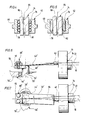
- FIGS. 6 and 7 A simplified second variant compared to the first variant, shown in FIGS. 6 and 7, is provided with the same reference numerals insofar as the same parts are used, so that reference is made in this regard to the explanations for the first variant.
- the tool drive shaft 44 'does not extend through the gear housing 46', but is only supported in the region of the lower part 50 ', the upper section 48' being a shaft stub projecting into the gear housing 46 '.
- the arm 42 'in contrast to the first variant is not made of rigid material, but of material which can spring up and down in the direction parallel to the axis 58' of the tool drive shaft 44 ', so that the pin 40 up and down in the plane of symmetry 84 is pivotable, while between the pin 40 and the upper portion 48 'of the tool drive shaft 44' in the direction perpendicular to the plane of symmetry 84 is a rigid connection.
- the arm 42 ' is preferably formed from a spring plate, which is in the direction perpendicular to the plane of symmetry has a substantially greater width than in its thickness measured parallel to the plane of symmetry 84.
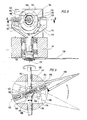
- the drive shaft 100 carries a swash bearing designated as a whole as 102, which carries an inner bearing part 104 seated on the drive shaft 100 with a circular path 106 rotating around the drive shaft 100 , whose center lies on the drive shaft axis 108, but whose path plane 110 encloses an angle with the drive shaft axis, which is preferably in a range between 85 to 90 °.
- This circular path 106 is designed as an orbit for rolling elements 112 of the wobble bearing 102, which in turn run in a bearing outer ring 114, so that the bearing outer ring can be rotated by the rolling elements 112 in the path plane 110 relative to the bearing inner part 104.
- the track plane 110 carries out wobbling movements around the drive shaft axis 108, whereby the free rotation of the outer bearing ring 114 relative to the inner bearing part 104 does not require the former to rotate with the drive shaft 100.
- the bearing outer ring 114 is in turn held in a holder 116 which has pins 118 arranged on opposite sides and coaxially to one another, which together form a pivot axis 120, which preferably runs through the center of the circular path 106 and also intersects the drive shaft axis 108 therein.
- the pins 118 are mounted in a fork 122 encompassing the socket 116, which in turn is connected in a rotationally fixed manner to the tool drive shaft 124.
- the axis 126 of the tool drive shaft 124 preferably runs perpendicular to the drive shaft axis 124 and through the center of the circular path 106.
- Rotation of the drive shaft 100 now causes the inner bearing part 104 to rotate with it and thus the path plane 110 performs wobbling movements.
- the bearing outer ring 114 which is rotatable with respect to the bearing inner part 104, does not rotate in this case, but only performs the wobble movements, with the pivoting axis 120 running in the path plane 110 not transmitting all the tilting movements around the fork 122, but only the tilting movements about the axis 126 , so that the fork 122 ultimately performs a pivoting oscillating movement about the axis 126 with a pivoting angle which corresponds to twice the difference between a right angle and the angle of inclination of the plane of the path 110 to the drive shaft axis 108.
- a cutting knife 128 is shown as a tool in FIGS. 8 and 9. However, a grinding tool 56 shown in FIG. 1 can also be mounted on the tool drive shaft 124.
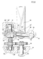
- a motor shaft 130 drives the drive shaft 100 'via two gear wheels 132, 134', on which the swash bearing 102 'sits.
- the inner bearing part 104 ' is not, as in the first variant, fixed on the drive shaft 100', but only non-rotatably, and is therefore displaceable in the direction of the drive shaft axis 108 'on the drive shaft 100'.
- the drive shaft 100 ' is provided with a spline 136, which engages in corresponding grooves in the bearing inner part 104'.
- the bearing outer ring 114 ' is provided with a radially extending rod 138 which extends through a rotationally fixed to the tool drive shaft 124' connected rod guide 140, in which the rod 138 is rotatable about its rod axis 142 and slidably in the longitudinal direction of the rod axis 142.
- the rod 138 is preferably circular cylindrical and the rod axis 142 is also oriented so that it extends perpendicular to the axis 126 'of the tool drive shaft 124' and intersects it.
- the rod axis 142 is expediently in the path plane 110 'of the wobble bearing 102' and intersects the drive shaft axis 108 '.
- a counterweight 139 is provided on an outer bearing ring 114 'opposite the end of the rod 138, which is necessary for a smoother run of the second variant.
- the wobble bearing 102' also performs wobble movements, with all pivoting movements about the rod axis 142 being able to take place freely.
- the rod guide 140 is rotatable about the axis 126 'of the tool drive shaft 124', the rod 138 can also pivot about this axis, for which purpose the swash bearing 102 'on the drive shaft 100' between its solid position and its dash-dotted position in Fig. 10 must be able to move up and down.
- the rod 138 is slidably mounted in the direction of the rod axis 142 in the rod guide 140.
- a swash plate 152 is mounted directly on the drive shaft 150, which has a front surface 154, which in the radial direction to the drive shaft axis 156 is always parallel to a perpendicular to this drive shaft axis 156 plane 158 runs, but in the course of a path orbit has a distance from this plane 158 that increases up to half a round and then decreases again to zero.
- Rolling bodies 162 which are guided in a cage 160 and with their axes of rotation radially aligned with the drive shaft axis 156, abut on this front surface 154 and act on a pressure disk 164 on their side opposite the front surface 154.
- Both the cage 160 and the thrust washer 164 each have a central recess 166 or 168, with which they are guided on a shaft stub 170 projecting beyond the front surface 154 and coaxial to the drive shaft 150, but do not rotate with the shaft stub 170.
- the cage 160 and the thrust washer 164 can be tilted with respect to the stub shaft 70, so that it is possible for them to follow the movements of the rolling elements 162 in the direction of the drive shaft axis 156 and also to carry out movements in this direction.
- the thrust washer 164 rests with a pressure surface 172 opposite the rolling elements 162 on a swivel part 176 which is fixedly connected to the tool drive shaft 174 and which can be rotated with the tool drive shaft 174 about its axis 178, the axis 178 preferably running perpendicular to the drive shaft axis 156.
- a contact surface 180 of the swivel part 176 facing the pressure surface 172 of the pressure disc 164 is designed such that it has a rectilinear edge 182 which intersects the drive shaft axis 156 and is preferably perpendicular to the axis 178.
- the support surface 180 is chamfered in the direction of the axis 178, so that the edge 182 is the region of the support surface 180 which projects most in the direction of the pressure surface 172.
- the bevel is chosen so that it allows the thrust washer 164 to tilt on both sides of the edge 182 about a tilt axis formed by the edge 182, which is caused by the swash plate 152 and the rolling elements 162 acted upon by its front surface 154 when the drive shaft 150 is rotating.
- Tilting the pressure plate 164 only about an axis parallel to the axis 178 of the tool drive shaft 174 leads to one Action on the bearing surface 180 by the pressure surface 172 in the area of the edge 182 and thus at the same time causing the pivoting part 176 to pivot about the axis 178.
- a pivoting movement about the axis 178 is transmitted to the pivoting part 176, which in turn is transmitted via the tool drive shaft 174, for example, a cutting tool 184 is also pivoted in an oscillating manner.
Landscapes
- Engineering & Computer Science (AREA)
- Mechanical Engineering (AREA)
- General Engineering & Computer Science (AREA)
- Life Sciences & Earth Sciences (AREA)
- Forests & Forestry (AREA)
- Transmission Devices (AREA)
- Finish Polishing, Edge Sharpening, And Grinding By Specific Grinding Devices (AREA)
- Apparatuses For Generation Of Mechanical Vibrations (AREA)
Applications Claiming Priority (2)
| Application Number | Priority Date | Filing Date | Title |
|---|---|---|---|
| DE3840974A DE3840974A1 (de) | 1988-12-06 | 1988-12-06 | Oszillationsantrieb |
| DE3840974 | 1988-12-06 |
Publications (3)
| Publication Number | Publication Date |
|---|---|
| EP0372376A2 true EP0372376A2 (fr) | 1990-06-13 |
| EP0372376A3 EP0372376A3 (en) | 1990-11-28 |
| EP0372376B1 EP0372376B1 (fr) | 1993-05-12 |
Family
ID=6368503
Family Applications (1)
| Application Number | Title | Priority Date | Filing Date |
|---|---|---|---|
| EP89122051A Expired - Lifetime EP0372376B1 (fr) | 1988-12-06 | 1989-11-29 | Mécanisme d'entraînement oscillant |
Country Status (4)
| Country | Link |
|---|---|
| EP (1) | EP0372376B1 (fr) |
| JP (1) | JPH06100253B2 (fr) |
| KR (1) | KR930000570B1 (fr) |
| DE (2) | DE3840974A1 (fr) |
Cited By (19)
| Publication number | Priority date | Publication date | Assignee | Title |
|---|---|---|---|---|
| EP0610801A1 (fr) * | 1993-02-04 | 1994-08-17 | Robert Bosch Gmbh | Outil à main de surfaçage |
| EP0623422A1 (fr) * | 1993-05-05 | 1994-11-09 | C. & E. FEIN GmbH & Co. | Outil électrique |
| EP0631843A1 (fr) * | 1993-07-01 | 1995-01-04 | Black & Decker Inc. | Ponceuse vibrante à deux plans de travail |
| EP0655023A4 (fr) * | 1992-08-14 | 1995-10-25 | Ryobi Motor Products Corp | Dispositif de pon age fin. |
| WO1997014531A1 (fr) * | 1995-10-18 | 1997-04-24 | Ab Dentatus | Appareil a main pour la man×uvre d'un outil en acces lateral |
| US5626510A (en) * | 1993-02-04 | 1997-05-06 | Robert Bosch Gmbh | Power tool for surface treatment |
| EP0799675A1 (fr) * | 1996-04-02 | 1997-10-08 | S.P. Air Kabusiki Kaisha | Outil motorisé abrasif |
| US6158528A (en) * | 2000-01-27 | 2000-12-12 | S.P. Air Kabusiki Kaisha | Hand-held pneumatic rotary drive device |
| US6179696B1 (en) | 1998-04-29 | 2001-01-30 | Black & Decker Inc. | Powered oscillating hand tool |
| US6443239B1 (en) | 2000-02-29 | 2002-09-03 | S.P. Air Kabusiki Kaisha | Pneumatic rotary tool |
| EP1358964A1 (fr) * | 2002-04-30 | 2003-11-05 | C. & E. Fein Gmbh & Co. KG | Générateur d'oscillations |
| EP1358965A3 (fr) * | 2002-04-30 | 2004-04-07 | C. & E. FEIN GmbH | Dispositif d'entraínement pour arbre oscillant |
| US6796386B2 (en) | 2000-09-08 | 2004-09-28 | S.P. Air Kabusiki Kaisha | Pneumatic rotary tool |
| GB2408708A (en) * | 2003-12-01 | 2005-06-08 | Bosch Gmbh Robert | Hand-held machine tool |
| US7404450B2 (en) | 2000-01-27 | 2008-07-29 | S.P. Air Kabusiki Kaisha | Pneumatic rotary tool |
| WO2009089940A1 (fr) * | 2008-01-16 | 2009-07-23 | Robert Bosch Gmbh | Machine-outil entraînée par un moteur |
| WO2014105943A1 (fr) * | 2012-12-31 | 2014-07-03 | Robert Bosch Gmbh | Entraînement à oscillation pour un outil oscillant |
| CN103939549A (zh) * | 2013-01-22 | 2014-07-23 | 陈伯均 | 锥动连杆机构 |
| US20180015567A1 (en) * | 2016-07-13 | 2018-01-18 | Lawrence Livermore National Security, Llc | Direct writing nozzle system for additive manufacturing |
Families Citing this family (20)
| Publication number | Priority date | Publication date | Assignee | Title |
|---|---|---|---|---|
| US5533926A (en) * | 1992-09-04 | 1996-07-09 | Ryobi North America | Sandpaper pad and pad support for a detail sander |
| US5637034A (en) * | 1993-08-13 | 1997-06-10 | Ryobi North America, Inc. | Detail sander |
| DE4344849A1 (de) * | 1993-12-29 | 1995-07-06 | Fein C & E | Werkzeugmaschine |
| US5607343A (en) * | 1994-08-22 | 1997-03-04 | Ryobi North America | Sander vibration isolator |
| US5759094A (en) | 1995-02-09 | 1998-06-02 | Porter-Cable Corporation | In-line detail sander |
| US5743791A (en) * | 1995-02-09 | 1998-04-28 | Porter Cable Corporation | Sanding system |
| DE10164081B4 (de) * | 2001-12-19 | 2012-01-26 | C. & E. Fein Gmbh | Oszillationswerkzeug mit Ausgleichsabschnitt |
| US6926595B2 (en) | 2002-04-30 | 2005-08-09 | C.&E. Fein Gmbh & Co. Kg | Oscillatory drive |
| DE202009011312U1 (de) | 2009-08-11 | 2010-12-23 | C. & E. Fein Gmbh | Handwerkzeug mit einem Oszillationsantrieb |
| US8365419B2 (en) * | 2009-09-29 | 2013-02-05 | Robert Bosch Gmbh | Accessory attachment system for an oscillating power tool |
| DE102011015117A1 (de) * | 2011-03-22 | 2012-09-27 | C. & E. Fein Gmbh | Handwerkzeug |
| JP2013031906A (ja) * | 2011-08-02 | 2013-02-14 | Makita Corp | 往復回転式電動工具 |
| DE102013100085A1 (de) * | 2013-01-07 | 2014-07-10 | C. & E. Fein Gmbh | Oszillierend angetriebene Werkzeugmaschine |
| DE102013002727A1 (de) | 2013-02-16 | 2014-08-21 | Heule Werkzeug Ag | Antriebsvorrichtung zur Ausübung einer Schub- und Drehbewegung an einer Antriebswelle zum Antrieb eines Entgratwerkzeuges und Verfahren zum Betrieb |
| US10252441B2 (en) | 2013-08-28 | 2019-04-09 | Corning Incorporated | System and method for cutting a wet green ceramic article |
| DE102014102128A1 (de) * | 2014-02-19 | 2015-08-20 | C. & E. Fein Gmbh | Oszillationsantrieb |
| DE102015226029A1 (de) * | 2015-12-18 | 2017-06-22 | Robert Bosch Gmbh | Motorisch angetriebene Handwerkzeugmaschine |
| FR3059264B1 (fr) * | 2016-11-29 | 2019-05-10 | Mure Et Peyrot | Couteau electrique |
| WO2020175009A1 (fr) * | 2019-02-28 | 2020-09-03 | 工機ホールディングス株式会社 | Engin de chantier |
| CN110722607B (zh) * | 2019-10-18 | 2021-08-31 | 苏州劲山电动工具有限公司 | 一种平衡手持式工具高频摆动机构振动的结构 |
Family Cites Families (9)
| Publication number | Priority date | Publication date | Assignee | Title |
|---|---|---|---|---|
| DE8031084U1 (de) * | 1981-07-23 | C. & E. Fein Gmbh & Co, 7000 Stuttgart | Elektrowerkzeug mit oszillierendem Werkzeugantrieb | |
| DE143844C (fr) * | ||||
| US2697897A (en) * | 1950-01-12 | 1954-12-28 | Peninsula Tool Company Inc | Rubbing machine |
| US2639620A (en) * | 1950-10-16 | 1953-05-26 | Frank L Bamford | Reciprocator |
| US3740847A (en) * | 1971-02-04 | 1973-06-26 | W Kliever | Power driven meat trimming and cutting knife |
| CH532139A (de) * | 1972-03-02 | 1972-12-31 | Mueller Jakob | Vorrichtung zur Umwandlung einer Drehbewegung in eine Schwingbewegung in Schmalwebmaschinen |
| IT1158620B (it) * | 1980-02-20 | 1987-02-18 | Ferrari Fernando Spa Off Mec | Gruppo di comando per barre falcianti in genere |
| DE3430562C1 (de) * | 1984-08-20 | 1985-11-21 | Braun Ag, 6000 Frankfurt | Vorrichtung zur Umwandlung einer Drehbewegung in eine hin- und hergehende Bewegung |
| DE8529622U1 (de) * | 1985-10-18 | 1986-01-23 | Chicago Pneumatic Zweigniederlassung der Chicago Pneumatic Tool Co. (West Germany), 6222 Geisenheim | Antrieb für ein oszillierendes Werkzeug |
-
1988
- 1988-12-06 DE DE3840974A patent/DE3840974A1/de not_active Ceased
-
1989
- 1989-11-29 DE DE8989122051T patent/DE58904346D1/de not_active Expired - Fee Related
- 1989-11-29 EP EP89122051A patent/EP0372376B1/fr not_active Expired - Lifetime
- 1989-12-05 JP JP1314466A patent/JPH06100253B2/ja not_active Expired - Lifetime
- 1989-12-06 KR KR1019890018098A patent/KR930000570B1/ko not_active Expired - Fee Related
Cited By (32)
| Publication number | Priority date | Publication date | Assignee | Title |
|---|---|---|---|---|
| EP0655023A4 (fr) * | 1992-08-14 | 1995-10-25 | Ryobi Motor Products Corp | Dispositif de pon age fin. |
| EP0610801A1 (fr) * | 1993-02-04 | 1994-08-17 | Robert Bosch Gmbh | Outil à main de surfaçage |
| US5626510A (en) * | 1993-02-04 | 1997-05-06 | Robert Bosch Gmbh | Power tool for surface treatment |
| EP0623422A1 (fr) * | 1993-05-05 | 1994-11-09 | C. & E. FEIN GmbH & Co. | Outil électrique |
| US5441450A (en) * | 1993-05-05 | 1995-08-15 | C.&E. Fein Gmbh & Co. | Power tool having means to switch from oscillatory movement to rotary movement |
| EP0631843A1 (fr) * | 1993-07-01 | 1995-01-04 | Black & Decker Inc. | Ponceuse vibrante à deux plans de travail |
| WO1997014531A1 (fr) * | 1995-10-18 | 1997-04-24 | Ab Dentatus | Appareil a main pour la man×uvre d'un outil en acces lateral |
| US5993304A (en) * | 1995-10-18 | 1999-11-30 | Ab Dentatus | Hand-held apparatus for sideways driving of a tool |
| EP0799675A1 (fr) * | 1996-04-02 | 1997-10-08 | S.P. Air Kabusiki Kaisha | Outil motorisé abrasif |
| US5919085A (en) * | 1996-04-02 | 1999-07-06 | S.P. Air Kabusiki Kaisha | Power abrading tool having dust abatement feature |
| USRE40345E1 (en) * | 1998-04-29 | 2008-05-27 | Black & Decker, Inc. | Powered oscillating hand tool |
| US6179696B1 (en) | 1998-04-29 | 2001-01-30 | Black & Decker Inc. | Powered oscillating hand tool |
| US6158528A (en) * | 2000-01-27 | 2000-12-12 | S.P. Air Kabusiki Kaisha | Hand-held pneumatic rotary drive device |
| USRE39009E1 (en) * | 2000-01-27 | 2006-03-14 | S.P. Air Kabusiki Kaisha | Hand-held pneumatic rotary drive device |
| US7404450B2 (en) | 2000-01-27 | 2008-07-29 | S.P. Air Kabusiki Kaisha | Pneumatic rotary tool |
| US6443239B1 (en) | 2000-02-29 | 2002-09-03 | S.P. Air Kabusiki Kaisha | Pneumatic rotary tool |
| US6796386B2 (en) | 2000-09-08 | 2004-09-28 | S.P. Air Kabusiki Kaisha | Pneumatic rotary tool |
| EP1358964A1 (fr) * | 2002-04-30 | 2003-11-05 | C. & E. Fein Gmbh & Co. KG | Générateur d'oscillations |
| EP1358965A3 (fr) * | 2002-04-30 | 2004-04-07 | C. & E. FEIN GmbH | Dispositif d'entraínement pour arbre oscillant |
| DE10220325B4 (de) * | 2002-04-30 | 2011-06-01 | C. & E. Fein Gmbh | Oszillationsantrieb |
| GB2408708A (en) * | 2003-12-01 | 2005-06-08 | Bosch Gmbh Robert | Hand-held machine tool |
| US7108077B2 (en) | 2003-12-01 | 2006-09-19 | Robert Bosch Gmbh | Power tool |
| GB2408708B (en) * | 2003-12-01 | 2005-11-16 | Bosch Gmbh Robert | Hand-held machine tool |
| WO2009089940A1 (fr) * | 2008-01-16 | 2009-07-23 | Robert Bosch Gmbh | Machine-outil entraînée par un moteur |
| RU2484939C2 (ru) * | 2008-01-16 | 2013-06-20 | Роберт Бош Гмбх | Технологическая машина с приводом от двигателя |
| US8720162B2 (en) | 2008-01-16 | 2014-05-13 | Robert Bosch Gmbh | Motor-driven machine tool |
| CN101909815B (zh) * | 2008-01-16 | 2014-10-15 | 罗伯特·博世有限公司 | 马达驱动的工具机 |
| WO2014105943A1 (fr) * | 2012-12-31 | 2014-07-03 | Robert Bosch Gmbh | Entraînement à oscillation pour un outil oscillant |
| US9561569B2 (en) | 2012-12-31 | 2017-02-07 | Robert Bosch Tool Corporation | Wobble drive for an oscillating tool |
| CN103939549A (zh) * | 2013-01-22 | 2014-07-23 | 陈伯均 | 锥动连杆机构 |
| US20180015567A1 (en) * | 2016-07-13 | 2018-01-18 | Lawrence Livermore National Security, Llc | Direct writing nozzle system for additive manufacturing |
| US10730138B2 (en) * | 2016-07-13 | 2020-08-04 | Lawrence Livermore National Security, Llc | Direct writing nozzle system for additive manufacturing |
Also Published As
| Publication number | Publication date |
|---|---|
| JPH06100253B2 (ja) | 1994-12-12 |
| EP0372376A3 (en) | 1990-11-28 |
| DE58904346D1 (de) | 1993-06-17 |
| DE3840974A1 (de) | 1990-06-07 |
| KR930000570B1 (ko) | 1993-01-25 |
| EP0372376B1 (fr) | 1993-05-12 |
| JPH02209653A (ja) | 1990-08-21 |
| KR900010270A (ko) | 1990-07-07 |
Similar Documents
| Publication | Publication Date | Title |
|---|---|---|
| EP0372376A2 (fr) | Mécanisme d'entraînement oscillant | |
| DE69922925T2 (de) | Säge mit hin und her gehendem sägeblatt | |
| DE102006041430B4 (de) | Werkzeugmaschine mit Motorantrieb | |
| DE10035357B4 (de) | Säge mit hin- und hergehender Schnittbewegung mit einstellbarem Hub | |
| DE2951647A1 (de) | Getriebe fuer eine maschine mit hin- und hergehenden kolben mit veraenderlichem hub | |
| DE3705461C2 (fr) | ||
| DE2343540B2 (de) | Gleichgang-Universalgelenk des Tripod-Typs | |
| DD209678A5 (de) | Gleichlauf-antriebsgelenk, insbesondere fuer schienenloses kraftfahrzeug | |
| DE19508708A1 (de) | Lenksystem mit variablem Lenkwinkelverhältnis | |
| DD284828A5 (de) | Vorrichtung zum antrieb einer werkzeugspindel | |
| EP0309762B1 (fr) | Machine à piston axial réglable du type à plateau incliné | |
| DE10057807C2 (de) | Verstelleinrichtung für Funktionsparameter bei einem Unwucht-Schwingungserreger | |
| DE4237463C2 (de) | Ausgleichsgetriebe | |
| DE3308935C2 (de) | Gleichlaufgelenk, insbesondere mit großem Beugewinkel | |
| EP0218831B1 (fr) | Entraînement pour un outil oscillant | |
| DE285517C (fr) | ||
| DE60105252T2 (de) | Höhenverstellvorrichtung für eine Tischplatte | |
| DE3203139C2 (de) | Winkelbewegliches Gleichlaufgelenk | |
| CH682646A5 (de) | Hubantriebseinheit für ein Werkzeug. | |
| DE2608919C2 (fr) | ||
| DE963487C (de) | Stufenlos regelbares Getriebe | |
| CH674628A5 (en) | Power driven compass saw | |
| DE7003350U (de) | Einrichtung zur halterung eines werkstuecks zur bewegung mit bezug auf eine schleifscheibe. | |
| DE3738150C2 (fr) | ||
| DE2508784A1 (de) | Trockenrasierer |
Legal Events
| Date | Code | Title | Description |
|---|---|---|---|
| PUAI | Public reference made under article 153(3) epc to a published international application that has entered the european phase |
Free format text: ORIGINAL CODE: 0009012 |
|
| AK | Designated contracting states |
Kind code of ref document: A2 Designated state(s): CH DE FR GB IT LI NL SE |
|
| PUAL | Search report despatched |
Free format text: ORIGINAL CODE: 0009013 |
|
| RHK1 | Main classification (correction) |
Ipc: F16H 21/40 |
|
| AK | Designated contracting states |
Kind code of ref document: A3 Designated state(s): CH DE FR GB IT LI NL SE |
|
| 17P | Request for examination filed |
Effective date: 19910314 |
|
| 17Q | First examination report despatched |
Effective date: 19920218 |
|
| GRAA | (expected) grant |
Free format text: ORIGINAL CODE: 0009210 |
|
| AK | Designated contracting states |
Kind code of ref document: B1 Designated state(s): CH DE FR GB IT LI NL SE |
|
| PG25 | Lapsed in a contracting state [announced via postgrant information from national office to epo] |
Ref country code: IT Free format text: LAPSE BECAUSE OF FAILURE TO SUBMIT A TRANSLATION OF THE DESCRIPTION OR TO PAY THE FEE WITHIN THE PRE;WARNING: LAPSES OF ITALIAN PATENTS WITH EFFECTIVE DATE BEFORE 2007 MAY HAVE OCCURRED AT ANY TIME BEFORE 2007. THE CORRECT EFFECTIVE DATE MAY BE DIFFERENT FROM THE ONE RECORDED.SCRIBED TIME-LIMIT Effective date: 19930512 Ref country code: SE Effective date: 19930512 Ref country code: NL Effective date: 19930512 |
|
| GBT | Gb: translation of ep patent filed (gb section 77(6)(a)/1977) |
Effective date: 19930519 |
|
| REF | Corresponds to: |
Ref document number: 58904346 Country of ref document: DE Date of ref document: 19930617 |
|
| ET | Fr: translation filed | ||
| NLV1 | Nl: lapsed or annulled due to failure to fulfill the requirements of art. 29p and 29m of the patents act | ||
| PGFP | Annual fee paid to national office [announced via postgrant information from national office to epo] |
Ref country code: GB Payment date: 19981012 Year of fee payment: 10 |
|
| PGFP | Annual fee paid to national office [announced via postgrant information from national office to epo] |
Ref country code: FR Payment date: 19981015 Year of fee payment: 10 |
|
| PGFP | Annual fee paid to national office [announced via postgrant information from national office to epo] |
Ref country code: CH Payment date: 19981023 Year of fee payment: 10 |
|
| PG25 | Lapsed in a contracting state [announced via postgrant information from national office to epo] |
Ref country code: GB Free format text: LAPSE BECAUSE OF NON-PAYMENT OF DUE FEES Effective date: 19991129 |
|
| PG25 | Lapsed in a contracting state [announced via postgrant information from national office to epo] |
Ref country code: LI Free format text: LAPSE BECAUSE OF NON-PAYMENT OF DUE FEES Effective date: 19991130 Ref country code: CH Free format text: LAPSE BECAUSE OF NON-PAYMENT OF DUE FEES Effective date: 19991130 |
|
| REG | Reference to a national code |
Ref country code: CH Ref legal event code: PL |
|
| GBPC | Gb: european patent ceased through non-payment of renewal fee |
Effective date: 19991129 |
|
| PG25 | Lapsed in a contracting state [announced via postgrant information from national office to epo] |
Ref country code: FR Free format text: LAPSE BECAUSE OF NON-PAYMENT OF DUE FEES Effective date: 20000731 |
|
| REG | Reference to a national code |
Ref country code: FR Ref legal event code: ST |
|
| PGFP | Annual fee paid to national office [announced via postgrant information from national office to epo] |
Ref country code: DE Payment date: 20061123 Year of fee payment: 18 |
|
| PG25 | Lapsed in a contracting state [announced via postgrant information from national office to epo] |
Ref country code: DE Free format text: LAPSE BECAUSE OF NON-PAYMENT OF DUE FEES Effective date: 20080603 |
|
| PLBE | No opposition filed within time limit |
Free format text: ORIGINAL CODE: 0009261 |
|
| STAA | Information on the status of an ep patent application or granted ep patent |
Free format text: STATUS: NO OPPOSITION FILED WITHIN TIME LIMIT |