EP0372396A1 - Ensemble porte/couvercle pour conduit de chute gravitationnel - Google Patents
Ensemble porte/couvercle pour conduit de chute gravitationnel Download PDFInfo
- Publication number
- EP0372396A1 EP0372396A1 EP89122111A EP89122111A EP0372396A1 EP 0372396 A1 EP0372396 A1 EP 0372396A1 EP 89122111 A EP89122111 A EP 89122111A EP 89122111 A EP89122111 A EP 89122111A EP 0372396 A1 EP0372396 A1 EP 0372396A1
- Authority
- EP
- European Patent Office
- Prior art keywords
- ledge
- section
- sidewall
- door
- extending
- Prior art date
- Legal status (The legal status is an assumption and is not a legal conclusion. Google has not performed a legal analysis and makes no representation as to the accuracy of the status listed.)
- Withdrawn
Links
- 230000005484 gravity Effects 0.000 title claims abstract description 39
- 238000011144 upstream manufacturing Methods 0.000 claims description 7
- 238000007599 discharging Methods 0.000 claims 3
- 230000000903 blocking effect Effects 0.000 claims 2
- 238000000034 method Methods 0.000 claims 1
- 229910000831 Steel Inorganic materials 0.000 description 3
- 239000010813 municipal solid waste Substances 0.000 description 3
- 239000010959 steel Substances 0.000 description 3
- 239000000463 material Substances 0.000 description 2
- 238000010276 construction Methods 0.000 description 1
- 230000008878 coupling Effects 0.000 description 1
- 238000010168 coupling process Methods 0.000 description 1
- 238000005859 coupling reaction Methods 0.000 description 1
Images

Classifications
-
- E—FIXED CONSTRUCTIONS
- E04—BUILDING
- E04F—FINISHING WORK ON BUILDINGS, e.g. STAIRS, FLOORS
- E04F17/00—Vertical ducts; Channels, e.g. for drainage
- E04F17/10—Arrangements in buildings for the disposal of refuse
- E04F17/12—Chutes
-
- B—PERFORMING OPERATIONS; TRANSPORTING
- B65—CONVEYING; PACKING; STORING; HANDLING THIN OR FILAMENTARY MATERIAL
- B65F—GATHERING OR REMOVAL OF DOMESTIC OR LIKE REFUSE
- B65F1/00—Refuse receptacles; Accessories therefor
- B65F1/0093—Refuse receptacles; Accessories therefor specially adapted for collecting refuse from arrangements in buildings
-
- B—PERFORMING OPERATIONS; TRANSPORTING
- B65—CONVEYING; PACKING; STORING; HANDLING THIN OR FILAMENTARY MATERIAL
- B65G—TRANSPORT OR STORAGE DEVICES, e.g. CONVEYORS FOR LOADING OR TIPPING, SHOP CONVEYOR SYSTEMS OR PNEUMATIC TUBE CONVEYORS
- B65G11/00—Chutes
- B65G11/20—Auxiliary devices, e.g. for deflecting, controlling speed of, or agitating articles or solids
- B65G11/206—Auxiliary devices, e.g. for deflecting, controlling speed of, or agitating articles or solids for bulk
Definitions
- This invention relates generally to the art of gravity conveyors, or chutes, which are often used for dropping trash from tall construction sites, such as buildings in a controlled manner.
- U.S. Patent 4,640,403 to McDermott describes a gravity-conveyor chute section having a side opening in a side panel thereof with a rotatable door/ledge assembly mounted thereat.
- the door/ledge assembly includes a ledge which can be moved between a closed position, flat against the side panel of the chute section, and a laterally-extending position in which it forms a ledge below the side opening.
- the door/ledge assembly of the McDermott patent also includes a frame having a door mounted thereon so that when the ledge is in the laterally-extending position the door can be opened and closed for controlling the use of the side opening.
- a door/ledge assembly for a gravity conveyor chute section has a ledge which is wider than a front panel at which the door/ledge assembly is mounted and first and second side supports extend from side edges of the ledge to left and right side panels of the section.
- first and second side supports slide along the left and right side panels.
- a door is hingedly attached to the ledge so that it can be rotated vertically between a laterally-extending position with the ledge in a closed position covering a side opening with or without the ledge.
- a lock is mounted above the side opening for locking both the ledge and door together covering the opening or for only locking the door covering the opening.
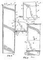
- a gravity conveyor chute section 10 comprises a tubular sidewall 12 defining a bore 14 and a side opening 16 in a front panel 18 thereof and a door/ledge assembly 20.
- the sidewall 12 is rectangular in cross-sectional shape and, in addition to the front panel 18, has left and right side panels 22 and 24.
- the bore 14 defines an upstream end opening 26 and a downstream end opening 28. It should be understood that ends of the gravity conveyor chute section 10 are to be telescoped with ends of other gravity conveyor chute sections so as to form a long gravity conveyor chute with each section serially receiving and further conveying materials deposited in the chute.
- this assembly comprises an approximately rectangularly-shaped ledge 30 which is hingedly mounted to the sidewall 12 below the side opening 16. It should be noted that the ledge 30 is wider than the front panel 18 so that first and second side edges 32 and 34 thereof extend beyond first and second side edges 36 and 38 of the front panel 18.
- first and second ledge-hinge brackets 40 and 42 are mounted to the left and right side panels 22 and 24 respectively.
- the first and second ledge-hinge brackets 40 and 42 are mirror images of one another, therefore, only one ledge-hinge bracket will be described.
- the ledge-hinge brackets have bottom and top plates 44 and 46 which are parallel to one another, but which are offset from one another by a bent portion 48.
- a section of the bottom plate 44 is welded to its respective sidewall with a portion of the ledge-hinge bracket extending beyond the front panel 18 as can be seen in the drawings.
- the top plate 46 is spaced from its respective side panel so as to form a slot 50 therebetween.
- a ledge-hinge pin, or shaft, 52 extends through holes in the top plates 46 of those portions extending beyond the front panel 18 and is rotatable in these holes.
- the ledge 30 is, in turn, welded at 54 to the ledge-hinge pin 52. This structure allows the ledge 30 to be rotated upwardly to a closed position against the front panel 18, closing the side opening 16 as is depicted in Fig. 5, or to a laterally-extending position, as is depicted in Figs. 1 and 2, to form a ledge for the side opening 16.
- first and second side supports 56 and 58 Attached to the ledge 30, at the first and second side edges 32 and 34 thereof, are first and second side supports 56 and 58. These supports have rear edge portions 60 which, when the ledge 30 is in the laterally-extending position, extend beyond the first and second side edges 36 and 38 of the front panel 18 to be adjacent to the left and right side panels 22 and 24. In this position, ledge-support pins or bolts 62 can be extended through openings 64 in the first and second side supports 56 and 58 and through the left and right side panels 22 and 24 to support the ledge 30. Although not shown in the drawings, additional supports can be provided on the right and left side panels 22 and 24 to reinforce them at positions engaged by the bolts 62.
- a pipe hinge 70 has alternate adjacent sections 72a and 72b.
- the pipe sections 72a are welded to a lower end 74 of the door 68 while the other sections 72b are welded to the top surface 66 of the ledge 30.
- a door pin 76 passes through all of the pipe sections 72a and 72b to thereby allow the door 68 to be rotated relative to the ledge 30. If the ledge 30 is rotated to a closed position on the ledge-hinge pin 52, the door 68 will automatically also be in a closed position on the front panel 18 covering the side opening 16. However, if the ledge 30 is in a laterally-extending position, the door 68 can either be in a closed position, as shown in Fig. 1, or in a laterally-extending position as shown in bold lines in Fig. 4.
- a bolt-locking assembly 78 is mounted on the front panel 18 above the opening 16 with a bolt 80 which can be moved in a cylinder 82 by means of a knob 84 either to a down, or locking, position as shown in Fig. 5 or to an up, or unlocking, position as shown in Fig. 4.
- the bolt-locking assembly 78 can be locked in either position so that only one with a key can open it.
- the section 10 is telescoped with other sections (not shown) to form a gravity conveyor chute beside a building with the opening 16 being at a floor level of the building.
- the bolt-locking assembly 78 is moved to an unlocking position and the ledge 30 is rotated downwardly to be in a laterally-extending position as shown in Fig. 1 for forming a ledge for the opening 16.
- the door 68 can be rotated downwardly about the door pin 76 to be relatively flush against the ledge, as shown in Fig. 4, to thereby form a portion of the ledge, or it can be rotated upwardly to a closed position as shown in Fig. 1.
- the bolt-locking assembly 78 can be used for locking the door 68 in a closed position.
- the ledge 30 is rotated upwardly about the ledge-hinge pin 52 and locked in a closed position by the bolt-locking assembly 78.
- the bolt-locking assembly 78 can be used both for locking the door 68 alone and for locking the ledge 30 and the door 68 together.
- the first and second side supports 56 and 58 slide along the left and right side panels 22 and 24 to be relatively flush therewith.
- the door/ledge assembly 20 is in a closed position as depicted in dashed lines in Fig.
- first and second side supports 56 and 58 slide along the left and right side panels 22 and 24, they also rotate in the slots 50 of the first and second ledge/hinge brackets 40 and 42.
- the various parts of the gravity conveyor chute section 10 are made of steel, with the door pin 76 being a 3/4 inch rod and the ledge/hinge pin 52 being a 1 1/2 inch shaft.
- the ledge 30 and its first and second side supports 58 and 60 are of 3/16 inch plate steel while the door 68 is 1/8 inch plate steel. Both the door 68 and the ledge 30 are approximately 36 inches long in one embodiment.
- the gravity conveyor chute section of this invention can be used for a gravity conveyor chute with the door/ledge assembly 20 in the closed position because, when it is in the closed position it does not obstruct the bore 14. That is, if it is desired to use the gravity conveyor chute section 10 simply as a conveying section without a side opening, the door/ledge assembly 20 is locked in a closed position.
- Such a gravity conveyor chute section 10 with a closed door/ledge assembly can be placed on an angle to the vertical by positioning the door/ledge assembly 20 facing upwardly, thereby allowing a more streamlined back panel 86 to come in contact with materials conveyed by the section 10.
Landscapes
- Engineering & Computer Science (AREA)
- Architecture (AREA)
- Structural Engineering (AREA)
- Civil Engineering (AREA)
- Mechanical Engineering (AREA)
- Washing And Drying Of Tableware (AREA)
- Superstructure Of Vehicle (AREA)
Applications Claiming Priority (2)
| Application Number | Priority Date | Filing Date | Title |
|---|---|---|---|
| US28091488A | 1988-12-07 | 1988-12-07 | |
| US280914 | 1988-12-07 |
Publications (1)
| Publication Number | Publication Date |
|---|---|
| EP0372396A1 true EP0372396A1 (fr) | 1990-06-13 |
Family
ID=23075149
Family Applications (1)
| Application Number | Title | Priority Date | Filing Date |
|---|---|---|---|
| EP89122111A Withdrawn EP0372396A1 (fr) | 1988-12-07 | 1989-11-30 | Ensemble porte/couvercle pour conduit de chute gravitationnel |
Country Status (2)
| Country | Link |
|---|---|
| EP (1) | EP0372396A1 (fr) |
| CA (1) | CA2004722C (fr) |
Cited By (1)
| Publication number | Priority date | Publication date | Assignee | Title |
|---|---|---|---|---|
| WO2007079544A1 (fr) * | 2006-01-13 | 2007-07-19 | John Clement Preston | Goulotte d’évacuation |
Citations (4)
| Publication number | Priority date | Publication date | Assignee | Title |
|---|---|---|---|---|
| FR1029848A (fr) * | 1949-12-26 | 1953-06-08 | Dévaloir | |
| FR1342140A (fr) * | 1961-06-20 | 1963-11-08 | Georges Stocker Et Fils | Vidoir à ordures |
| FR2128895A5 (fr) * | 1971-03-08 | 1972-10-27 | Leonard Patrick | |
| US4640403A (en) * | 1985-02-13 | 1987-02-03 | Mcdermott Daniel R | Gravity-conveyor chute section |
-
1989
- 1989-11-30 EP EP89122111A patent/EP0372396A1/fr not_active Withdrawn
- 1989-12-06 CA CA 2004722 patent/CA2004722C/fr not_active Expired - Lifetime
Patent Citations (4)
| Publication number | Priority date | Publication date | Assignee | Title |
|---|---|---|---|---|
| FR1029848A (fr) * | 1949-12-26 | 1953-06-08 | Dévaloir | |
| FR1342140A (fr) * | 1961-06-20 | 1963-11-08 | Georges Stocker Et Fils | Vidoir à ordures |
| FR2128895A5 (fr) * | 1971-03-08 | 1972-10-27 | Leonard Patrick | |
| US4640403A (en) * | 1985-02-13 | 1987-02-03 | Mcdermott Daniel R | Gravity-conveyor chute section |
Cited By (1)
| Publication number | Priority date | Publication date | Assignee | Title |
|---|---|---|---|---|
| WO2007079544A1 (fr) * | 2006-01-13 | 2007-07-19 | John Clement Preston | Goulotte d’évacuation |
Also Published As
| Publication number | Publication date |
|---|---|
| CA2004722C (fr) | 2000-02-15 |
| CA2004722A1 (fr) | 1990-06-07 |
Similar Documents
| Publication | Publication Date | Title |
|---|---|---|
| US4640403A (en) | Gravity-conveyor chute section | |
| US5090546A (en) | Door/ledge assembly for gravity chute | |
| US6092580A (en) | Garage child/pet/ventilation gate | |
| CA2118161C (fr) | Conteneur a ordures pour collecte selective et attache pour le transport par camion | |
| CA2109248C (fr) | Benne de camion munie d'un convoyeur integre | |
| US5295743A (en) | Secure cabinets | |
| US4565261A (en) | Detachable gallery for use on buildings or the like | |
| US20050077107A1 (en) | Scaffold system with telescoping access ladder and resiliently hinged scaffold access hatch deck | |
| US20040061341A1 (en) | Trash container locking apparatus and method | |
| US3709345A (en) | Double passage silo chute | |
| US4838598A (en) | Segmented end gate for box type vehicle bodifs | |
| US20220079365A1 (en) | Garage Door Parcel Receptacle | |
| US5001861A (en) | Automatic universal deadbolt locking device | |
| IE901109A1 (en) | A Security Unit | |
| CN212126228U (zh) | 集装箱 | |
| CA2004722C (fr) | Porte a feuillure pour goulotte | |
| EP0536129B1 (fr) | Porte laterale de decharge de conteneur | |
| US4799528A (en) | Closure device | |
| GB2179389A (en) | Child-proof safety gate | |
| GB2241526A (en) | Security door arrangement | |
| EP0607040B1 (fr) | Amélioration concernant des couvertures de sécurité pour des ouvertures de portes ou fenêtres | |
| GB2212542A (en) | Security door assembly | |
| EP0388668B1 (fr) | Dispositif d'accrochage pour un transporteur aérien | |
| US5035416A (en) | Sliding ice rink door | |
| GB2209558A (en) | Rear face hinge |
Legal Events
| Date | Code | Title | Description |
|---|---|---|---|
| PUAI | Public reference made under article 153(3) epc to a published international application that has entered the european phase |
Free format text: ORIGINAL CODE: 0009012 |
|
| AK | Designated contracting states |
Kind code of ref document: A1 Designated state(s): AT BE CH DE ES FR GB GR IT LI LU NL SE |
|
| 17P | Request for examination filed |
Effective date: 19901205 |
|
| 17Q | First examination report despatched |
Effective date: 19910909 |
|
| STAA | Information on the status of an ep patent application or granted ep patent |
Free format text: STATUS: THE APPLICATION IS DEEMED TO BE WITHDRAWN |
|
| 18D | Application deemed to be withdrawn |
Effective date: 19921107 |