EP0372442A2 - Schaltgerät - Google Patents
Schaltgerät Download PDFInfo
- Publication number
- EP0372442A2 EP0372442A2 EP89122289A EP89122289A EP0372442A2 EP 0372442 A2 EP0372442 A2 EP 0372442A2 EP 89122289 A EP89122289 A EP 89122289A EP 89122289 A EP89122289 A EP 89122289A EP 0372442 A2 EP0372442 A2 EP 0372442A2
- Authority
- EP
- European Patent Office
- Prior art keywords
- switching device
- infrared
- switching
- lighting
- sunlight
- Prior art date
- Legal status (The legal status is an assumption and is not a legal conclusion. Google has not performed a legal analysis and makes no representation as to the accuracy of the status listed.)
- Granted
Links
Images
Classifications
-
- H—ELECTRICITY
- H01—ELECTRIC ELEMENTS
- H01H—ELECTRIC SWITCHES; RELAYS; SELECTORS; EMERGENCY PROTECTIVE DEVICES
- H01H47/00—Circuit arrangements not adapted to a particular application of the relay and designed to obtain desired operating characteristics or to provide energising current
- H01H47/22—Circuit arrangements not adapted to a particular application of the relay and designed to obtain desired operating characteristics or to provide energising current for supplying energising current for relay coil
- H01H47/24—Circuit arrangements not adapted to a particular application of the relay and designed to obtain desired operating characteristics or to provide energising current for supplying energising current for relay coil having light-sensitive input
-
- H—ELECTRICITY
- H05—ELECTRIC TECHNIQUES NOT OTHERWISE PROVIDED FOR
- H05B—ELECTRIC HEATING; ELECTRIC LIGHT SOURCES NOT OTHERWISE PROVIDED FOR; CIRCUIT ARRANGEMENTS FOR ELECTRIC LIGHT SOURCES, IN GENERAL
- H05B47/00—Circuit arrangements for operating light sources in general, i.e. where the type of light source is not relevant
- H05B47/10—Controlling the light source
- H05B47/105—Controlling the light source in response to determined parameters
- H05B47/11—Controlling the light source in response to determined parameters by determining the brightness or colour temperature of ambient light
-
- H—ELECTRICITY
- H01—ELECTRIC ELEMENTS
- H01H—ELECTRIC SWITCHES; RELAYS; SELECTORS; EMERGENCY PROTECTIVE DEVICES
- H01H23/00—Tumbler or rocker switches, i.e. switches characterised by being operated by rocking an operating member in the form of a rocker button
-
- H—ELECTRICITY
- H02—GENERATION; CONVERSION OR DISTRIBUTION OF ELECTRIC POWER
- H02J—ELECTRIC POWER NETWORKS; CIRCUIT ARRANGEMENTS OR SYSTEMS FOR SUPPLYING OR DISTRIBUTING ELECTRIC POWER; SYSTEMS FOR STORING ELECTRIC ENERGY
- H02J13/00—Circuit arrangements for providing remote monitoring or remote control of equipment in a power distribution network
- H02J13/13—Circuit arrangements for providing remote monitoring or remote control of equipment in a power distribution network characterised by the transmission of data to equipment in the power network
- H02J13/1327—Circuit arrangements for providing remote monitoring or remote control of equipment in a power distribution network characterised by the transmission of data to equipment in the power network using optical means
-
- H—ELECTRICITY
- H02—GENERATION; CONVERSION OR DISTRIBUTION OF ELECTRIC POWER
- H02J—ELECTRIC POWER NETWORKS; CIRCUIT ARRANGEMENTS OR SYSTEMS FOR SUPPLYING OR DISTRIBUTING ELECTRIC POWER; SYSTEMS FOR STORING ELECTRIC ENERGY
- H02J13/00—Circuit arrangements for providing remote monitoring or remote control of equipment in a power distribution network
- H02J13/18—Circuit arrangements for providing remote monitoring or remote control of equipment in a power distribution network characterised by the remotely-controlled equipment, e.g. converters or transformers
- H02J13/34—Circuit arrangements for providing remote monitoring or remote control of equipment in a power distribution network characterised by the remotely-controlled equipment, e.g. converters or transformers the equipment being switches, relays or circuit breakers
-
- Y—GENERAL TAGGING OF NEW TECHNOLOGICAL DEVELOPMENTS; GENERAL TAGGING OF CROSS-SECTIONAL TECHNOLOGIES SPANNING OVER SEVERAL SECTIONS OF THE IPC; TECHNICAL SUBJECTS COVERED BY FORMER USPC CROSS-REFERENCE ART COLLECTIONS [XRACs] AND DIGESTS
- Y02—TECHNOLOGIES OR APPLICATIONS FOR MITIGATION OR ADAPTATION AGAINST CLIMATE CHANGE
- Y02B—CLIMATE CHANGE MITIGATION TECHNOLOGIES RELATED TO BUILDINGS, e.g. HOUSING, HOUSE APPLIANCES OR RELATED END-USER APPLICATIONS
- Y02B20/00—Energy efficient lighting technologies, e.g. halogen lamps or gas discharge lamps
- Y02B20/40—Control techniques providing energy savings, e.g. smart controller or presence detection
Definitions
- the invention relates to a switching device with a circuit arrangement according to the preamble of claim 1.
- DE-OS 14 90 471 discloses a circuit arrangement for switching a consumer on or off, in particular a lighting system, as a function of the light intensity.
- the light intensity is recorded by a photo element which controls the switching contact of an electromagnetic relay via evaluation electronics, the switching contact in turn switching a lighting system on or off.
- the sunlight brightness sensor can be installed inexpensively at locations which make it possible to correctly differentiate daylight from artificial light of the existing room lighting.
- individually adjustable and wiring-saving lighting of the room to be monitored can be achieved.
- artificial light is switched on when the natural light falls below an individually perceived brightness value, but not switched off again when the brightness value of natural light that has been reached in the meantime would be sufficient again.
- the circuit arrangement according to the invention can therefore help to reduce the overall lighting costs.
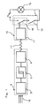
- Figure 1 shows a sunlight brightness sensor 3 (e.g. a photo element) onto which sunlight radiation 16 falls.
- PCM pulse code modulation
- the infrared radiation pulse 17 received by an infrared receiver 11 is fed to a second switch contact 18, preferably a semiconductor switch which, in addition to an already installed manually operable first switch contact 12 of the switching device 1, is looped into the power supply line for one or more lighting fixtures 15 is.
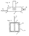
- FIG. 2 shows a housing 7 of the transmitting part 2 of the invention, which is pivotably mounted on a mounting bracket 8 circuit arrangement according to the invention.
- the mounting bracket 8 is preferably attached near the window so that the existing daylight brightness can be detected well.
- the housing 7 must be adjusted so that the infrared radiation pulse 17 leaving the infrared transmitter 6 hits the infrared receiver 11 integrated in the switching device 1.
- the power supply of the transmitting part 2 is optionally provided by a battery or mains connection 9.
- the mounting bracket 8 is designed so that the mounting of the transmitter part 2 is possible both on concrete ceilings and on suspended ceilings.
- FIG. 3 shows a switching device 1 usually installed in building lighting technology with a cover frame 14 and a manually actuable switching rocker 13, which in turn switches the first switching contact 12.
- the series connection of the two switching contacts 12, 18 ensures that the power supply circuit for a lighting fixture 15 is interrupted after activation of the circuit arrangement according to the invention, even when the manually operable switching contact 12 is switched on. If the brightness value set on the circuit arrangement according to the invention is subjectively perceived to be too low in the room to be monitored, the activation threshold of the circuit arrangement can be raised by adjusting the threshold value at the threshold switch 5.
Landscapes
- Circuit Arrangement For Electric Light Sources In General (AREA)
- Arrangement Of Elements, Cooling, Sealing, Or The Like Of Lighting Devices (AREA)
- Eye Examination Apparatus (AREA)
- Seal Device For Vehicle (AREA)
- Vehicle Body Suspensions (AREA)
- Lubricants (AREA)
- Gas-Insulated Switchgears (AREA)
- Hydrogenated Pyridines (AREA)
Abstract
Description
- Die Erfindung betrifft ein Schaltgerät mit einer Schaltungsanordnung nach dem Oberbegriff des Anspruchs 1.
- Aus der DE-OS 14 90 471 ist eine Schaltungsanordnung zur An- bzw. Abschaltung eines Verbrauchers, insbesondere einer Beleuchtungsanlage, in Abhängigkeit von der Lichtstärke bekannt. Hierbei wird die Lichtstärke von einem Photoelement aufgenommen, welches über eine Auswerteelektronik den Schaltkontakt eines elektromagnetischen Relais ansteuert, wobei der Schaltkontakt seinerseits eine Beleuchtungsanlage ein- oder ausschaltet.
- Bei bestimmten Applikationen (z.B. Beleuchtungssteuerung in der Gebäudeinstallationstechnik) ist es jedoch wirtschaftlich nachteilig, wenn der Ort, wo sich der Helligkeitssensor befindet und der Ort, wo sich der Schaltkontakt des Schaltgeräts befindet mit Verbindungsleitungen überbrückt werden muß. Ferner ist nachteilig, daß bei bekannten Beleuchtungssteuerungen die Schaltgeräte noch nicht in handelsübliche Unterputz-Wandeinbaudosen integriert werden können.
- Es ist deshalb Aufgabe vorliegender Erfindung, die im Stand der Technik bekannte Schaltungsanordnung für Zwecke der Gebäudeinstallationstechnik so auszubilden, daß bei fest vorgegeben installierten und manuell ein- bzw. ausschaltbaren Schaltgeräten eine zusatzlich in Abhängigkeit vom Sonnenlicht zu steuernde Schaltung installierter Beleuchtungskörper erfolgen kann.
- Diese Aufgabe wird erfindungsgemäß durch die im Anspruch 1 näher gekennzeichneten Merkmale gelöst.
- Erfindungsgemäß wird erreicht, daß der Sonnenlicht-Helligkeitssensor kostengünstig an Stellen installiert werden kann, die es ermöglichen, das Tageslicht vom künstlichen Licht der vorhandenen Raumbeleuchtung einwandfrei zu unterscheiden. Hierdurch kann eine individuell einzustellende und Verdrahtungsaufwand sparende Beleuchtung des zu überwachenden Raums erreicht werden. Insbesondere in Bürogebäuden wird nämlich künstliches Licht zwar eingeschaltet, wenn das natürliche Licht einen individuell als optimal empfundenen Helligkeitswert unterschreitet, nicht aber wieder ausgeschaltet, wenn der zwischenzeitlich erreicht Helligkeitswert des natürlichen Lichts wieder ausreichend wäre.
- Die erfindungsgemäße Schaltungsanordnung kann daher dazu beitragen, die insgesamt auflaufenden Beleutungskosten abzusenken.
- Vorteilhafte Weiterbildungen des Erfindungsgegenstandes sind in den Unteransprüchen näher gekennzeichnet.
- Anhand eines in der Zeichnung dargestellten Ausführungsbeispiels soll die Erfindung näher erläutert und beschrieben werden.
- Es zeigen:
- Figur 1: Ein Prinzipschaltbild der erfindungsgemäßen Schaltungsanordnung, mit einem IR-Sendeteil 2 und einem IR-Empfangsteil 10,
- Figur 2: den in einem Gehäuse 7 untergebrachten Sendeteil 2 der erfindungsgemäßen Schaltungsanordnung in Kompaktbauweise nebst Befestigungsbügel 8,
- Figur 3: ein üblicherweise in der Hausinstallationstechnik installiertes Schaltgerät 1 für Beleuchtungskörper nebst integriertem Infrarot-Empfänger 11.
- Figur 1 zeigt einen Sonnenlicht-Helligkeitssensor 3 (z.B. ein Photoelement), auf welchen Sonnenlichtstrahlung 16 fällt. Der dem Helligkeitswert des natürlichen Sonnenlichts entsprechend erzeugte Stromwert wird einem Schwellwertschalter 5 zugeführt, welcher beim Überschreiten eines vorgegebenen, individuell einzustellenden Werts einen nachgeschalteten Infrarot-Sender 6 veranlaßt, einen vorzugsweise codierten (PCM=Pulscodemodulation) Infrarot-Strahlungsimpuls 17 abzugeben. Der von einem Infrarot-Empfänger 11 aufgenommene Infrarot-Strahlungsimpuls 17 wird einem zweiten Schaltkontakt 18 vorzugsweise einem Halbleiter-Schalter zugeführt, welcher zusätzlich in Serie zu einem bereits installierten manuell betätigbaren ersten Schaltkontakt 12 des Schaltgeräts 1 in die Stromversorgungsleitung für einen oder mehrere Beleuchtungskörper 15 eingeschleift ist.
- Figur 2 zeigt ein an einem Befestigungsbügel 8 schwenkbar gelagertes Gehäuse 7 des Sendeteils 2 der erfin dungsgemäßen Schaltungsanordnung. Der Befestigungsbügel 8 wird vorzugsweise in Fensternähe angebracht, so daß die vorhandene Tageslichthelligkeit gut detektiert werden kann. Das Gehäuse 7 muß so justiert werden, daß der den Infrarot-Sender 6 verlassende Infrarot-Strahlungsimpuls 17 auf den am Schaltgerät 1 integrierten Infrarot-Empfänger 11 trifft. Die Stromversorgung des Sendeteils 2 wird wahlweise durch einen Batterie- oder Netzanschluß 9 bereitgestellt. Der Befestigungsbügel 8 wird so ausgelegt, daß die Halterung des Sendeteils 2 sowohl an Betondecken als auch an abgehängten Decken möglich ist.
- Figur 3 zeigt ein in der Gebäudebeleuchtungstechnik üblicherweise installiertes Schaltgerät 1 mit einem Abdeckrahmen 14 und einer manuell betätigbaren Schaltwippe 13, welche ihrerseits den ersten Schaltkontakt 12 schaltet.
- Durch die Hintereinanderschaltung der beiden Schaltkontakte 12,18 wird erreicht, daß der Stromversorgungskreis für einen Beleuchtungskörper 15 nach Aktivierung der erfindungsgemäßen Schaltungsanordnung unterbrochen wird, auch wenn der manuell betätigbare Schaltkontakt 12 eingeschaltet ist. Sollte der an der erfindungsgemäßen Schaltungsanordnung eingestellte Helligkeitswert im zu überwachenden Raum subjektiv als zu niedrig empfunden werden, kann durch Verstellen des Schwellwerts am Schwellwertschalter 5 die Aktivierungsschwelle der Schaltungsanordnung heraufgesetzt werden.
Claims (5)
Priority Applications (1)
| Application Number | Priority Date | Filing Date | Title |
|---|---|---|---|
| AT89122289T ATE100981T1 (de) | 1988-12-08 | 1989-12-02 | Schaltgeraet. |
Applications Claiming Priority (2)
| Application Number | Priority Date | Filing Date | Title |
|---|---|---|---|
| DE8815289U DE8815289U1 (de) | 1988-12-08 | 1988-12-08 | Schaltgerät |
| DE8815289U | 1988-12-08 |
Publications (3)
| Publication Number | Publication Date |
|---|---|
| EP0372442A2 true EP0372442A2 (de) | 1990-06-13 |
| EP0372442A3 EP0372442A3 (en) | 1990-08-29 |
| EP0372442B1 EP0372442B1 (de) | 1994-01-26 |
Family
ID=6830598
Family Applications (1)
| Application Number | Title | Priority Date | Filing Date |
|---|---|---|---|
| EP89122289A Expired - Lifetime EP0372442B1 (de) | 1988-12-08 | 1989-12-02 | Schaltgerät |
Country Status (3)
| Country | Link |
|---|---|
| EP (1) | EP0372442B1 (de) |
| AT (1) | ATE100981T1 (de) |
| DE (2) | DE8815289U1 (de) |
Cited By (4)
| Publication number | Priority date | Publication date | Assignee | Title |
|---|---|---|---|---|
| DE9017355U1 (de) * | 1990-12-22 | 1992-04-23 | Popp + Co Gmbh, 8582 Bad Berneck | Elektro-Installationsschalter |
| FR2676842A1 (fr) * | 1991-05-22 | 1992-11-27 | Somfy | Installation de commande automatique du niveau d'eclairement d'un local. |
| DE19823422A1 (de) * | 1998-05-15 | 1999-11-18 | Ernst Slamecka | Drahtlos helligkeitsgesteuerter elektrischer Schalter |
| WO2002029364A1 (de) * | 2000-09-22 | 2002-04-11 | Pepperl + Fuchs Gmbh | Sensorvorrichtung |
Families Citing this family (1)
| Publication number | Priority date | Publication date | Assignee | Title |
|---|---|---|---|---|
| GB2294569A (en) * | 1994-10-17 | 1996-05-01 | Flecon Multi System Pte Ltd | Wireless control systems |
Family Cites Families (6)
| Publication number | Priority date | Publication date | Assignee | Title |
|---|---|---|---|---|
| DE1490471A1 (de) * | 1963-09-30 | 1969-06-12 | Siemens Ag | Schaltungsanordnung zur An- bzw. Abschaltung eines Verbrauchers,insbesondere einer Beleuchtungsanlage,in Abhaengigkeit der Lichtstaerke |
| FR2449994A1 (fr) * | 1979-02-23 | 1980-09-19 | Thionvilloise Immobiliere | Telecommande de dispositifs electriques |
| US4449074A (en) * | 1983-02-23 | 1984-05-15 | Lutron Electronics Co., Inc. | Excess light turn-off circuit |
| CH662223A5 (en) * | 1983-03-15 | 1987-09-15 | Sulzer Ag | Optoelectrical control module and use thereof |
| GB2155708B (en) * | 1984-02-24 | 1988-02-10 | Colin Robert Francis | Electrical devices |
| US4663521A (en) * | 1985-02-15 | 1987-05-05 | Rca Corporation | Infrared radiation controlled switch with a visible light detector |
-
1988
- 1988-12-08 DE DE8815289U patent/DE8815289U1/de not_active Expired
-
1989
- 1989-12-02 AT AT89122289T patent/ATE100981T1/de active
- 1989-12-02 EP EP89122289A patent/EP0372442B1/de not_active Expired - Lifetime
- 1989-12-02 DE DE89122289T patent/DE58906826D1/de not_active Expired - Fee Related
Cited By (9)
| Publication number | Priority date | Publication date | Assignee | Title |
|---|---|---|---|---|
| DE9017355U1 (de) * | 1990-12-22 | 1992-04-23 | Popp + Co Gmbh, 8582 Bad Berneck | Elektro-Installationsschalter |
| FR2676842A1 (fr) * | 1991-05-22 | 1992-11-27 | Somfy | Installation de commande automatique du niveau d'eclairement d'un local. |
| EP0517650A1 (de) * | 1991-05-22 | 1992-12-09 | Somfy | Schaltungsanordnung zur automatischen Steuerung der Beleuchtungsstärke in einem Raum |
| DE19823422A1 (de) * | 1998-05-15 | 1999-11-18 | Ernst Slamecka | Drahtlos helligkeitsgesteuerter elektrischer Schalter |
| WO2002029364A1 (de) * | 2000-09-22 | 2002-04-11 | Pepperl + Fuchs Gmbh | Sensorvorrichtung |
| AU2001293823B2 (en) * | 2000-09-22 | 2005-07-28 | Pepperl + Fuchs Gmbh | Sensor device |
| AU2001293823C1 (en) * | 2000-09-22 | 2006-02-09 | Pepperl + Fuchs Gmbh | Sensor device |
| AU2001293823B9 (en) * | 2000-09-22 | 2006-08-31 | Pepperl + Fuchs Gmbh | Sensor device |
| US7139159B2 (en) | 2000-09-22 | 2006-11-21 | Pepper1 + Fuchs Gmbh | Sensor device |
Also Published As
| Publication number | Publication date |
|---|---|
| DE58906826D1 (de) | 1994-03-10 |
| DE8815289U1 (de) | 1989-03-09 |
| EP0372442A3 (en) | 1990-08-29 |
| EP0372442B1 (de) | 1994-01-26 |
| ATE100981T1 (de) | 1994-02-15 |
Similar Documents
| Publication | Publication Date | Title |
|---|---|---|
| DE69324357T2 (de) | Überwachungs- und alarmvorrichtung für räume. | |
| EP2211084B1 (de) | Leuchte, insbesondere Wandleuchte | |
| DE3322729C2 (de) | ||
| DE29815154U1 (de) | Fernsteuerbarer Wandschalter | |
| EP0372442A2 (de) | Schaltgerät | |
| EP0625817A1 (de) | Bedieneinheit für Installationsgeräte | |
| US20040195982A1 (en) | Controlling device for use with exterior landscape lighting assemblies | |
| EP0372441A1 (de) | Passiv-Infrarot Bewegungsmelder | |
| DE4419019A1 (de) | Schalt- und Dimmervorrichtung und Verfahren zur Anwendung | |
| EP1962391A2 (de) | Installationsgerät mit integrierter Not- und Orientierungsbeleuchtung | |
| EP1843366A1 (de) | Elektrisches/elektronisches Installationsgerät mit Bewegungsmelder und manueller Schalteinrichtung | |
| EP0103040B1 (de) | Fernschalter mit einer Empfangs- und Steuerelektronik | |
| DE19623481C2 (de) | Automatische Leuchtensteuerungsvorrichtung mit Dopplerradarmodul, welches in eine Unterputzdose einbaubar ist | |
| DE3941167C1 (de) | ||
| DE19814488A1 (de) | Funklichtdimmer für Glühlampen | |
| DE9310534U1 (de) | Eine Beleuchtungseinrichtung, die durch eine IR-Fernbedienung ein- bzw. ausgeschaltet werden kann und zwischen Lampenfassung und Glühbirne eingeschraubt wird | |
| DE3610112A1 (de) | Treppenlichtzeitschalter | |
| DE29609453U1 (de) | Zentrales Ferntastsystem | |
| NL8300270A (nl) | Energie besparende schakelinrichting. | |
| EP3089318B1 (de) | Vorrichtung zur durchgängigen versorgung eines verbrauchers mit elektrischer ernergie | |
| DE102018100285B3 (de) | Taster-Vorrichtung und System mit einer Taster-Vorrichtung | |
| DE19930329C2 (de) | Anordnung zum Einstellen und Bedienen von festinstallierten Schaltsignalgebern | |
| DE19543378A1 (de) | Verfahren und Schaltung zur Steuerung elektrischer Verbraucher | |
| DE29705599U1 (de) | Zentrales Ferntastsystem zur Beleuchtungssteuerung in Wohn- oder Büroeinheiten | |
| DE29817814U1 (de) | Elektrisches Installationssystem |
Legal Events
| Date | Code | Title | Description |
|---|---|---|---|
| PUAI | Public reference made under article 153(3) epc to a published international application that has entered the european phase |
Free format text: ORIGINAL CODE: 0009012 |
|
| AK | Designated contracting states |
Kind code of ref document: A2 Designated state(s): AT CH DE LI NL |
|
| PUAL | Search report despatched |
Free format text: ORIGINAL CODE: 0009013 |
|
| AK | Designated contracting states |
Kind code of ref document: A3 Designated state(s): AT CH DE LI NL |
|
| 17P | Request for examination filed |
Effective date: 19910124 |
|
| 17Q | First examination report despatched |
Effective date: 19930420 |
|
| GRAA | (expected) grant |
Free format text: ORIGINAL CODE: 0009210 |
|
| AK | Designated contracting states |
Kind code of ref document: B1 Designated state(s): AT CH DE LI NL |
|
| REF | Corresponds to: |
Ref document number: 100981 Country of ref document: AT Date of ref document: 19940215 Kind code of ref document: T |
|
| REF | Corresponds to: |
Ref document number: 58906826 Country of ref document: DE Date of ref document: 19940310 |
|
| PLBE | No opposition filed within time limit |
Free format text: ORIGINAL CODE: 0009261 |
|
| STAA | Information on the status of an ep patent application or granted ep patent |
Free format text: STATUS: NO OPPOSITION FILED WITHIN TIME LIMIT |
|
| PG25 | Lapsed in a contracting state [announced via postgrant information from national office to epo] |
Ref country code: AT Effective date: 19941202 |
|
| PG25 | Lapsed in a contracting state [announced via postgrant information from national office to epo] |
Ref country code: LI Effective date: 19941231 Ref country code: CH Effective date: 19941231 |
|
| 26N | No opposition filed | ||
| PG25 | Lapsed in a contracting state [announced via postgrant information from national office to epo] |
Ref country code: NL Effective date: 19950701 |
|
| REG | Reference to a national code |
Ref country code: CH Ref legal event code: PL |
|
| NLV4 | Nl: lapsed or anulled due to non-payment of the annual fee |
Effective date: 19950701 |
|
| PGFP | Annual fee paid to national office [announced via postgrant information from national office to epo] |
Ref country code: DE Payment date: 20011026 Year of fee payment: 13 |
|
| PG25 | Lapsed in a contracting state [announced via postgrant information from national office to epo] |
Ref country code: DE Free format text: LAPSE BECAUSE OF NON-PAYMENT OF DUE FEES Effective date: 20030701 |