EP0372443A2 - Casque pour sécher les cheveux - Google Patents
Casque pour sécher les cheveux Download PDFInfo
- Publication number
- EP0372443A2 EP0372443A2 EP89122294A EP89122294A EP0372443A2 EP 0372443 A2 EP0372443 A2 EP 0372443A2 EP 89122294 A EP89122294 A EP 89122294A EP 89122294 A EP89122294 A EP 89122294A EP 0372443 A2 EP0372443 A2 EP 0372443A2
- Authority
- EP
- European Patent Office
- Prior art keywords
- hood
- air
- cap
- heating elements
- outlet openings
- Prior art date
- Legal status (The legal status is an assumption and is not a legal conclusion. Google has not performed a legal analysis and makes no representation as to the accuracy of the status listed.)
- Granted
Links
Images


Classifications
-
- A—HUMAN NECESSITIES
- A45—HAND OR TRAVELLING ARTICLES
- A45D—HAIRDRESSING OR SHAVING EQUIPMENT; EQUIPMENT FOR COSMETICS OR COSMETIC TREATMENTS, e.g. FOR MANICURING OR PEDICURING
- A45D20/00—Hair drying devices; Accessories therefor
-
- A—HUMAN NECESSITIES
- A45—HAND OR TRAVELLING ARTICLES
- A45D—HAIRDRESSING OR SHAVING EQUIPMENT; EQUIPMENT FOR COSMETICS OR COSMETIC TREATMENTS, e.g. FOR MANICURING OR PEDICURING
- A45D20/00—Hair drying devices; Accessories therefor
- A45D20/20—Helmets without hot air supply or other ventilation, e.g. electrically heated
-
- A—HUMAN NECESSITIES
- A45—HAND OR TRAVELLING ARTICLES
- A45D—HAIRDRESSING OR SHAVING EQUIPMENT; EQUIPMENT FOR COSMETICS OR COSMETIC TREATMENTS, e.g. FOR MANICURING OR PEDICURING
- A45D20/00—Hair drying devices; Accessories therefor
- A45D20/22—Helmets with hot air supply or ventilating means, e.g. electrically heated air current
-
- A—HUMAN NECESSITIES
- A45—HAND OR TRAVELLING ARTICLES
- A45D—HAIRDRESSING OR SHAVING EQUIPMENT; EQUIPMENT FOR COSMETICS OR COSMETIC TREATMENTS, e.g. FOR MANICURING OR PEDICURING
- A45D20/00—Hair drying devices; Accessories therefor
- A45D20/22—Helmets with hot air supply or ventilating means, e.g. electrically heated air current
- A45D20/24—Shape or structure of the helmet body
-
- A—HUMAN NECESSITIES
- A45—HAND OR TRAVELLING ARTICLES
- A45D—HAIRDRESSING OR SHAVING EQUIPMENT; EQUIPMENT FOR COSMETICS OR COSMETIC TREATMENTS, e.g. FOR MANICURING OR PEDICURING
- A45D20/00—Hair drying devices; Accessories therefor
- A45D20/22—Helmets with hot air supply or ventilating means, e.g. electrically heated air current
- A45D20/24—Shape or structure of the helmet body
- A45D2020/245—Shape or structure of the helmet body of open configuration, e.g. with several movable heat sources
Definitions
- the invention relates to a head dryer hood with heating elements, in particular infrared radiators, and blowers.
- the known devices are usually bell-shaped and are perceived as too warm due to the build-up of heat.
- the extensive covering of the head gives the user a tight feeling.
- a laterally open, approximately crescent-shaped, curved cap with heating elements is used according to the invention, with one arm on both sides of one end toward the other end Heating elements and in opposite In the direction of a box-shaped extension with the blower.
- the heat generated by the heating elements primarily supports the chemical processes, particularly in the case of perms
- the air generated by the blower can accelerate the drying process by removing the moisture. Due to the side openings, the tight feeling for the user is eliminated and the hairdresser can easily reach through on the head to further work on the hairstyle during the drying process.
- the cap preferably extends from the neck downward by a section in order to also completely grasp the neck hair.
- the arms are expediently articulated on the cap or on the neck and slightly bent outwards. The fact that the arms can be pivoted means that the hairdresser can continue to work even during the drying process and can pivot the arms away if he wants to work on the parts of the hairstyle that they cover.
- the blower is connected to the longitudinal air channels in the cap and / or the arms, which have appropriately aligned air outlet openings.
- the air outlet openings are preferably nozzle-shaped and in particular arranged obliquely so that the air jet does not hit the head vertically but as tangentially as possible.
- duct covers with air outlet openings which are designed as reflectors, the heating elements protected by gratings being located in front of these reflectors.
- the air is led from the fan to the air ducts via one or more additional heating elements.
- the cap is U-shaped in cross-section and two air ducts are arranged in parallel therein. These preferably extend approximately over the width of the cap and lie one above the other.
- the partition between the channels ends approximately in the lower third of the cap.
- the air flow of the duct directly bordering the air outlet openings runs through the additional heating elements.
- the other channel expediently does not carry heated air, since the reflectors heat up in the apex of the cap due to the heating elements and thereby also heat the air flowing past there. If one would also preheat this air, there would be a very uneven heat distribution over the entire area of the cap.
- the heated air of the duct lying at the air outlet openings is already blown out in the lower part of the cap, that is to say at a point which has only a slight heating of the reflectors located there.
- balls which are connected to the arms and which, in particular, have through-bores for the connection between the blower and the air channels.
- sleeves connected to the arms can also be used, which are rotatably and longitudinally displaceably mounted in hollow cylinders arranged with the cap. The rotational and longitudinal displaceability of the sleeves is limited by stops, and one or more locking positions are provided.
- a particularly simple construction of the hood is obtained if the cap with a shoulder is divided in two approximately at the height of the articulation of the arms, half-shells or hollow cylinders being provided in each part for the storage of the ball or sleeves connected to the arms.
- Electric heating elements designed as infrared radiators are mostly used for warmers for air drying the hair. It is expedient to wind the wire turns arranged on the emitters tightly on the outside and wide on the inside. The heat generated by the emitters is mostly concentrated in the middle of the cap cross section, so that it makes sense to heat this area less by the emitters and to generate more heat in the outer areas. A particularly simple attachment for the infrared radiators is obtained if resiliently mounted in the cap laterally contact pins, which also serve to supply electricity.
- a control device in particular pivotable, is preferably arranged on the box-shaped attachment for controlling fans and heating elements.
- a pivotable control device is expediently also used at the free end of the cap, especially for special functions.
- drying hood according to the invention drying without air supply as well as with any preselectable amount of air is possible. This results in easy adaptability of the drying conditions to a wide variety of hair types and hairstyles.
- an air duct with air outlet openings runs in the hood, with an additional heating element being located between the blower and the air duct and the air duct in the direction of flow the additional heating element has an outlet opening which is connected to outlet openings directed into the interior and arranged approximately at the lower end of the hood.
- a releasable closure is preferably attached to the outlet opening, so that the air flow directed into the neck area can only be switched on when necessary.
- the closure is connected to a control device for the free passage of the outlet opening.
- a secondary air duct is formed between the outlet opening of the air duct and the outlet openings of the hood. This creates a simple connection between the outlet opening and the outlet openings, since instead of individual air ducts there is a common secondary air duct connected to all outlet openings. Since the outlet openings are arranged so that the entire neck of the user can be cooled, the secondary air duct preferably extends over the width of the hood.
- At least one of the outlet openings has an air duct which runs obliquely downward to the inner wall of the hood.
- the air duct is preferably designed as a gap, the depth of which is approximately three times its width and extends at an angle of approximately 30 ° to the inner wall.
- an auxiliary air heater is in the secondary air duct is arranged.
- the air flow directed into the neck area can also be used to dry the neck hair when the auxiliary air heating is switched on.
- the secondary air heater is connected to a temperature control device.
- a variant of the invention provides that in a head dryer hood with heating elements, in particular infrared emitters and a blower, and with an operating device with display elements for blowers, heating elements, etc., the operating device has a display panel which can be folded onto the display elements and which has a switch for switching over the display elements when lying thereon operated.
- Various drying programs can be selected with the operating device, the display elements indicating the respective operating state. Additional operating states or drying programs can be displayed on the display panel, the switchover being implemented in a simple manner. It proves to be particularly advantageous if the switch consists of a magnet connected to the foldable display panel, in particular its axis of rotation, and a Hall contact arranged on the operating device.
- thermocouple In known head dryer hoods, the temperature control of the heating elements takes place via temperature sensors, which are usually clamped in the hair.
- a preferred embodiment of the invention provides that a pivotally mounted on the hood Temperature sensor, in particular thermocouple, protrudes into the interior of the hood and is connected to a heat control device of the heating elements.
- the process of attaching is now dispensed with, since the temperature sensor according to the invention automatically attaches itself to the user's hair and adapts to any change in position of the head. A simpler temperature control in every head position of the user is possible.
- the temperature sensor is expediently fastened to the crossbar of a U-shaped bracket, which is pivotably mounted on the hood with one end of each of the two bracket legs.
- Another advantageous embodiment results from a measuring device for the angle between the hood and the holder, which is connected to the heat control device of the heating elements. Since the angle is directly related to the head posture of the user, the heat control device can be controlled individually in each head position with this measuring device.
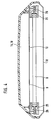
- the drying hood is composed of a crescent-shaped cap 1 and a box-shaped extension 2 located approximately at its lower end, the cap 1 still extending from the extension 2 by a portion 3 downwards.
- two arms 4 and 5 are pivotally mounted.
- the arms 4, 5 sleeves 6 are connected.
- In the cap 1 and the neck 2 there are hollow cylinders 7, in which these sleeves are longitudinally displaceable and rotatable.
- the cap 1 is U-shaped in cross-section and transversely to its longitudinal direction, uniformly distributed, there are electric infrared radiators (8), behind which there is a reflector 10 provided with air outlet openings 9.
- the arms 4 and 5 each have an infrared radiator 12 in a reflector housing 11.
- a tangential fan 13 is arranged in the box-shaped extension 2 net, whose air flow in the U-shaped cross section of the cap 1 extends longitudinally and exits through the air outlet openings 9 into the space between the cap 1 and the arms 4, 5.
- Two channels 15 and 16 are formed by a partition 14.
- An additional heating element 17 is arranged in the duct 16 located at the air outlet openings 9 for heating the air. The air that is heated as a result then largely exits in the lower part of the cap.
- air conveyed directly by the fan 13 flows without preheating into the upper and front part of the cap 1 and can exit there through the air outlet openings 9.
- the reflector 10 is heated so strongly by the infrared radiators 8 that the air is thereby already heated. In this way, a largely uniform heat distribution is obtained over the entire cap area.
- grids 18 and 19 are arranged in front of these.
- the infrared emitters 8 and 12 are held in sockets 25.
- contact pins 26 which are mounted in a longitudinally displaceable manner and are supported against springs and serve both to fix the infrared radiators 8, 12 and to supply current.
- a tripod mount 23 is also provided for the hood. Instead, a wall receptacle 24 can also be used.
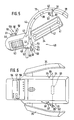
- the dryer hood according to FIGS. 5 and 6 are composed of a crescent-shaped cap 31 and a box-shaped extension 32 located approximately at its lower end, the cap 31 still extending from the extension 32 downward by a portion 33.
- two arms 34 and 35 are pivotally mounted.
- the cap 31 is U-shaped in cross-section and, uniformly distributed, electric infrared radiators 38 are arranged transversely to its longitudinal direction, behind which there is a reflector 40 provided with air outlet openings 39.
- the arms 34 and 35 each have an infrared radiator 42 in a reflector housing 41.
- a blower 43 is arranged in the box-shaped extension 32, the air flow of which runs longitudinally in an air channel 44 in the U-shaped cross section of the cap 31 and exits through the air outlet openings 39 into the space between the cap 31 and the arms 34, 35.
- An additional heating element 45 is arranged in the air duct 44 for heating the air.
- the air duct 44 has an outlet opening 47 in the direction of flow upstream of the additional heating element 45, which is designed as an opening in a guide plate 48.
- the baffle 48 extends from the blower 43 to the cap 31, where it is bent approximately at a right angle and led to the additional heating element 45.
- At the outlet opening 47 has a detachable closure which can be controlled by a control device (not shown in the drawing).
- the outlet opening 47 is connected in terms of flow via an auxiliary air duct 52 to outlet openings 46, 51 which are directed into the interior 49 of the cap 31 and are arranged above a lower end 50 of the drying hood.
- the secondary air duct 52 extends across the width of the hood.
- Those outlet openings 51 which are arranged close to the outlet opening 47, have an air duct 54 running obliquely downwards to the inner wall 53 of the hood.
- the depth of the air duct is approximately three times greater than its width and extends at an angle of approximately 30 ° to the inner wall 53.
- a further outlet opening 46 is arranged near the lower end 50 of the hood and is designed as a horizontal slot.
- a secondary air heater 55 is arranged within the secondary air duct 52 between the lower outlet opening 46 and the upper outlet openings 51 and is connected to a temperature control device, not shown in the drawing.
- an operating device 56 with display elements 57 for the operating state of the blower, heating elements and secondary air heating.
- a display panel 58 which can be folded onto the display elements 57 is pivotably mounted on the operating device 56.
- switch 59 consists of a magnet 60 connected to display panel 58 and a Hall contact 61 arranged on operating device 56.
- a temperature sensor 63 On the upper part of the cap 31 there is a U-shaped holder 62 for a temperature sensor 63, which consists of a cross bar 64 and the two holder legs 65. One end 66 of each of the two mounting legs 65 is pivotally mounted on the cap 31.
- the temperature sensor 63 is attached to the cross bar 64 and connected to a heat control device of the heating elements, not shown in the drawing.
- a measuring device 67 which measures the angle 68 between the cap 31 and the holder 62. It is connected to the heat control device of the heating elements and regulates the heating power of the heating elements depending on the size of the angle 68.
- the air generated by the fan 43 and heated by the additional heating element 45 is guided through the air duct 44 and the air outlet openings 39 into the interior 49 of the hood and thus to the hair of the user.
- a part of the cool air generated by the fan exits the additional heating element through an outlet opening 47 from the air duct 44 and is through the secondary air duct 52 and the outlet openings 51 with air duct 54 into the interior 49 of the Hood and thus led to the user's neck area, which is cooled by this air flow.
- the air flow can be switched on and off and its strength can be regulated.
- the air flow can also be guided to the neck area via the lower outlet opening 46, the secondary air heater 55 arranged in the secondary air duct 52 allowing this air flow to be heated, so that the drying process in the neck area can be accelerated if the user has long hair.
- Various drying programs are selected via the operating device 56 with display elements 57 for the operating states of blowers, heating elements, etc.
- the display panel 58 can be folded down onto the display elements 57, with a switch 59 for switching over the display panel 58 when it is in place Display elements 57 is operated.
- the heat control of the heating elements required for different drying programs is carried out via the temperature sensor 63. Because of its pivotable suspension via the holder 62 on the cap 31, the temperature sensor 63 can easily be placed on the hair of the head with different head positions.
- the change in the heat output of the heating elements required with different head positions is controlled by a measuring device 67.
- the measuring device 67 can be used, for example, as a slide Resistance be formed, the resistance changes when the user changes position by the change in angle between bracket 62 and cap 31.
Landscapes
- Cleaning And Drying Hair (AREA)
- Helmets And Other Head Coverings (AREA)
- Window Of Vehicle (AREA)
- Seal Device For Vehicle (AREA)
- Outer Garments And Coats (AREA)
- Drying Of Solid Materials (AREA)
Applications Claiming Priority (4)
| Application Number | Priority Date | Filing Date | Title |
|---|---|---|---|
| DE8815146U | 1988-12-06 | ||
| DE8815146U DE8815146U1 (de) | 1988-12-06 | 1988-12-06 | Kopftrockenhaube |
| DE8911354U | 1989-09-23 | ||
| DE8911354U DE8911354U1 (de) | 1989-09-23 | 1989-09-23 | Kopftrockenhaube |
Publications (3)
| Publication Number | Publication Date |
|---|---|
| EP0372443A2 true EP0372443A2 (fr) | 1990-06-13 |
| EP0372443A3 EP0372443A3 (fr) | 1992-01-22 |
| EP0372443B1 EP0372443B1 (fr) | 1994-08-10 |
Family
ID=25953851
Family Applications (1)
| Application Number | Title | Priority Date | Filing Date |
|---|---|---|---|
| EP89122294A Expired - Lifetime EP0372443B1 (fr) | 1988-12-06 | 1989-12-02 | Casque pour sécher les cheveux |
Country Status (8)
| Country | Link |
|---|---|
| US (1) | US5063688A (fr) |
| EP (1) | EP0372443B1 (fr) |
| JP (1) | JP3068833B2 (fr) |
| KR (1) | KR960014567B1 (fr) |
| CN (1) | CN1024999C (fr) |
| AT (1) | ATE109629T1 (fr) |
| DE (1) | DE58908183D1 (fr) |
| ES (1) | ES2061905T3 (fr) |
Cited By (6)
| Publication number | Priority date | Publication date | Assignee | Title |
|---|---|---|---|---|
| DE9318614U1 (de) * | 1993-12-06 | 1994-01-27 | Olymp Karl Herzog GmbH & Co, 70184 Stuttgart | Vorrichtung zur Haarbehandlung mit feuchten Medien |
| FR2707851A1 (fr) * | 1993-07-20 | 1995-01-27 | Seb Sa | Procédé et dispositif de séchage et/ou de mise en forme de cheveux à cycle et paramètres de séchage à variation automatique. |
| EP0695520A1 (fr) * | 1994-08-02 | 1996-02-07 | Wella Aktiengesellschaft | Appareil de traitement des cheveux avec élément de rayonnement infrarouge et une soufflante |
| WO2006091458A1 (fr) | 2005-02-23 | 2006-08-31 | The Procter & Gamble Company | Dispositif de thermotraitement capillaire |
| US7479618B2 (en) | 2005-02-28 | 2009-01-20 | The Procter & Gamble Company | Device for heat treatment |
| EP2020190A1 (fr) * | 2007-07-31 | 2009-02-04 | Wella Aktiengesellschaft | Dispositif de radiation à infrarouge |
Families Citing this family (22)
| Publication number | Priority date | Publication date | Assignee | Title |
|---|---|---|---|---|
| USD408100S (en) * | 1996-09-25 | 1999-04-13 | Oohiro Works Ltd. | Hair treatment promoting device |
| USD409331S (en) * | 1996-09-25 | 1999-05-04 | Oohiro Works Ltd. | Hair treatment promoting device |
| USD477111S1 (en) | 1999-08-07 | 2003-07-08 | Wella Ag | Hair dryer |
| DE10102832A1 (de) * | 2000-01-22 | 2001-07-26 | Wella Ag | Elektrisches Haarbehandlungsgerät |
| USD468483S1 (en) | 2000-08-08 | 2003-01-07 | Oohiro Works, Ltd. | Hair processing accelerator |
| KR100783442B1 (ko) * | 2000-09-08 | 2007-12-07 | 다카라 벨몬트 가부시키가이샤 | 모발처리촉진장치 |
| JP4456254B2 (ja) * | 2000-10-20 | 2010-04-28 | 株式会社大廣製作所 | 頭髪処理促進機 |
| USD474562S1 (en) | 2000-10-20 | 2003-05-13 | Oohiro Works, Ltd. | Hair processing accelerator |
| JP4435398B2 (ja) * | 2000-10-25 | 2010-03-17 | 株式会社大廣製作所 | 頭髪処理促進機 |
| JP4295440B2 (ja) * | 2001-01-09 | 2009-07-15 | 株式会社三龍社 | 同心逆回転減速機を有する頭髪加熱機 |
| KR20030030041A (ko) * | 2001-10-05 | 2003-04-18 | 임채윤 | 청정에어 공급형 다기능 미용기기 |
| KR20030083461A (ko) * | 2002-04-23 | 2003-10-30 | 송웅부 | 헤어 드라이 장치 |
| USD527490S1 (en) * | 2003-04-11 | 2006-08-29 | Wella Aktiengesellschaft | Hair dryer |
| WO2005102036A1 (fr) * | 2004-04-20 | 2005-11-03 | Thorsen, Roland | Methode et bonnet de traitement contre les poux et les lentes |
| EP1755316A4 (fr) | 2004-06-08 | 2009-08-12 | Mitsubishi Electric Corp | Dispositif mobile |
| CN100569139C (zh) * | 2005-02-28 | 2009-12-16 | 宝洁公司 | 用于进行热处理的装置 |
| USD622444S1 (en) | 2006-12-05 | 2010-08-24 | Wella Aktiengesellschaft | Hair drying hood |
| USD601750S1 (en) | 2007-10-19 | 2009-10-06 | Wella Aktiengesellschaft | Hair dryer |
| USD628343S1 (en) | 2008-04-17 | 2010-11-30 | Wella Aktiengesellschaft | Infrared radiation dryer |
| US8859938B2 (en) * | 2009-01-26 | 2014-10-14 | Nissan North America, Inc. | Vehicle cabin heating system |
| ES2795355T3 (es) * | 2009-07-10 | 2020-11-23 | Braun Gmbh | Proceso automatizado para el cuidado del cabello |
| CN107594847A (zh) * | 2017-09-20 | 2018-01-19 | 林广华 | 一种全方位吹风机 |
Family Cites Families (5)
| Publication number | Priority date | Publication date | Assignee | Title |
|---|---|---|---|---|
| DE3133851A1 (de) * | 1981-08-27 | 1983-03-24 | Wella Ag | Waermebehandlungsgeraet fuer kopfhaare |
| JPS5832075U (ja) * | 1981-08-28 | 1983-03-02 | 住友軽金属工業株式会社 | トラツク等のアオリパネル |
| JPS60101003U (ja) * | 1983-12-16 | 1985-07-10 | タカラベルモント株式会社 | 毛髪促進装置 |
| EP0156984B1 (fr) * | 1983-12-16 | 1990-04-25 | TAKARA COMPANY, Inc. | Appareil de traitement des cheveux |
| JPH0728770B2 (ja) * | 1987-11-24 | 1995-04-05 | タカラベルモント株式会社 | 毛髪処理促進装置 |
-
1989
- 1989-12-02 ES ES89122294T patent/ES2061905T3/es not_active Expired - Lifetime
- 1989-12-02 AT AT89122294T patent/ATE109629T1/de not_active IP Right Cessation
- 1989-12-02 DE DE58908183T patent/DE58908183D1/de not_active Expired - Lifetime
- 1989-12-02 EP EP89122294A patent/EP0372443B1/fr not_active Expired - Lifetime
- 1989-12-05 KR KR1019890018090A patent/KR960014567B1/ko not_active Expired - Lifetime
- 1989-12-06 US US07/446,617 patent/US5063688A/en not_active Expired - Lifetime
- 1989-12-06 JP JP1315526A patent/JP3068833B2/ja not_active Expired - Lifetime
- 1989-12-06 CN CN89109097A patent/CN1024999C/zh not_active Expired - Lifetime
Cited By (7)
| Publication number | Priority date | Publication date | Assignee | Title |
|---|---|---|---|---|
| FR2707851A1 (fr) * | 1993-07-20 | 1995-01-27 | Seb Sa | Procédé et dispositif de séchage et/ou de mise en forme de cheveux à cycle et paramètres de séchage à variation automatique. |
| DE9318614U1 (de) * | 1993-12-06 | 1994-01-27 | Olymp Karl Herzog GmbH & Co, 70184 Stuttgart | Vorrichtung zur Haarbehandlung mit feuchten Medien |
| EP0695520A1 (fr) * | 1994-08-02 | 1996-02-07 | Wella Aktiengesellschaft | Appareil de traitement des cheveux avec élément de rayonnement infrarouge et une soufflante |
| WO2006091458A1 (fr) | 2005-02-23 | 2006-08-31 | The Procter & Gamble Company | Dispositif de thermotraitement capillaire |
| US7479618B2 (en) | 2005-02-28 | 2009-01-20 | The Procter & Gamble Company | Device for heat treatment |
| EP2020190A1 (fr) * | 2007-07-31 | 2009-02-04 | Wella Aktiengesellschaft | Dispositif de radiation à infrarouge |
| WO2009016598A3 (fr) * | 2007-07-31 | 2009-03-26 | Procter & Gamble | Dispositif pour l'irradiation aux infrarouges des cheveux du cuir chevelu |
Also Published As
| Publication number | Publication date |
|---|---|
| KR900009005A (ko) | 1990-07-02 |
| KR960014567B1 (ko) | 1996-10-16 |
| JPH02243104A (ja) | 1990-09-27 |
| CN1043078A (zh) | 1990-06-20 |
| ATE109629T1 (de) | 1994-08-15 |
| DE58908183D1 (de) | 1994-09-15 |
| EP0372443B1 (fr) | 1994-08-10 |
| CN1024999C (zh) | 1994-06-15 |
| JP3068833B2 (ja) | 2000-07-24 |
| ES2061905T3 (es) | 1994-12-16 |
| EP0372443A3 (fr) | 1992-01-22 |
| US5063688A (en) | 1991-11-12 |
Similar Documents
| Publication | Publication Date | Title |
|---|---|---|
| EP0372443A2 (fr) | Casque pour sécher les cheveux | |
| DE4236036C2 (de) | Luftdurchströmbares Gerät zur Haartrocknung oder Haarformung | |
| DE3874687T2 (de) | Haartrockner. | |
| DE60112483T2 (de) | Haartrockner | |
| EP0772409A1 (fr) | Seche-cheveux tenu a la main | |
| WO1982003643A1 (fr) | Fer a repasser electrique notamment fer a repasser pour voyage | |
| DE69931906T2 (de) | Klimatisierungseinheit einer fahrzeugklimaanlage | |
| DE1757436C2 (de) | Elektrischer Haartrockner | |
| DE69910921T2 (de) | Gerät zum trocknen und formen von haaren | |
| DE60007646T2 (de) | Elektrisches gerät z.b. haartrockner mit in ihrer position veränderbaren schalter | |
| DE102018110805A1 (de) | Belüftungsvorrichtung für einen Kleinkindinkubator und Kleinkindinkubator | |
| DE3101933A1 (de) | Haarpflegegeraet mit einem warmluftgeblaese | |
| DE3442848C2 (de) | Backofen | |
| DE2614564B2 (de) | Heizvorrichtung | |
| EP0530726A1 (fr) | Appareil de chauffage multifonctionnel | |
| DE8911354U1 (de) | Kopftrockenhaube | |
| DE19504605C2 (de) | Transportable Vorrichtung zum Abtrocknen und/oder Kühlen des Körpers eines Individuums, insbesondere des menschlichen Körpers | |
| DE69518059T2 (de) | Tragbares Klimagerät | |
| DE8815146U1 (de) | Kopftrockenhaube | |
| DE102008059132A1 (de) | Luftleitsystem | |
| DE2400433A1 (de) | Haartrocknerduese | |
| DE3412848C2 (de) | Handhabungsgerät | |
| DE102019118772A1 (de) | Haartrockner | |
| DE20004686U1 (de) | Elektrischer Warmluft-Händetrockner | |
| DE3319403A1 (de) | Haarbehandlungsgeraet |
Legal Events
| Date | Code | Title | Description |
|---|---|---|---|
| PUAI | Public reference made under article 153(3) epc to a published international application that has entered the european phase |
Free format text: ORIGINAL CODE: 0009012 |
|
| AK | Designated contracting states |
Kind code of ref document: A2 Designated state(s): AT BE CH DE ES FR GB IT LI NL SE |
|
| RHK1 | Main classification (correction) |
Ipc: A45D 20/24 |
|
| PUAL | Search report despatched |
Free format text: ORIGINAL CODE: 0009013 |
|
| AK | Designated contracting states |
Kind code of ref document: A3 Designated state(s): AT BE CH DE ES FR GB IT LI NL SE |
|
| 17P | Request for examination filed |
Effective date: 19911213 |
|
| 17Q | First examination report despatched |
Effective date: 19930217 |
|
| GRAA | (expected) grant |
Free format text: ORIGINAL CODE: 0009210 |
|
| AK | Designated contracting states |
Kind code of ref document: B1 Designated state(s): AT BE CH DE ES FR GB IT LI NL SE |
|
| REF | Corresponds to: |
Ref document number: 109629 Country of ref document: AT Date of ref document: 19940815 Kind code of ref document: T |
|
| ET | Fr: translation filed | ||
| GBT | Gb: translation of ep patent filed (gb section 77(6)(a)/1977) |
Effective date: 19940812 |
|
| REF | Corresponds to: |
Ref document number: 58908183 Country of ref document: DE Date of ref document: 19940915 |
|
| ITF | It: translation for a ep patent filed | ||
| REG | Reference to a national code |
Ref country code: ES Ref legal event code: FG2A Ref document number: 2061905 Country of ref document: ES Kind code of ref document: T3 |
|
| EAL | Se: european patent in force in sweden |
Ref document number: 89122294.5 |
|
| PLBE | No opposition filed within time limit |
Free format text: ORIGINAL CODE: 0009261 |
|
| STAA | Information on the status of an ep patent application or granted ep patent |
Free format text: STATUS: NO OPPOSITION FILED WITHIN TIME LIMIT |
|
| 26N | No opposition filed | ||
| REG | Reference to a national code |
Ref country code: GB Ref legal event code: IF02 |
|
| PGFP | Annual fee paid to national office [announced via postgrant information from national office to epo] |
Ref country code: CH Payment date: 20081201 Year of fee payment: 20 Ref country code: NL Payment date: 20081219 Year of fee payment: 20 |
|
| PGFP | Annual fee paid to national office [announced via postgrant information from national office to epo] |
Ref country code: AT Payment date: 20081223 Year of fee payment: 20 |
|
| PGFP | Annual fee paid to national office [announced via postgrant information from national office to epo] |
Ref country code: IT Payment date: 20081219 Year of fee payment: 20 Ref country code: SE Payment date: 20081217 Year of fee payment: 20 |
|
| PGFP | Annual fee paid to national office [announced via postgrant information from national office to epo] |
Ref country code: ES Payment date: 20090129 Year of fee payment: 20 |
|
| PGFP | Annual fee paid to national office [announced via postgrant information from national office to epo] |
Ref country code: DE Payment date: 20090123 Year of fee payment: 20 |
|
| PGFP | Annual fee paid to national office [announced via postgrant information from national office to epo] |
Ref country code: GB Payment date: 20081126 Year of fee payment: 20 |
|
| PGFP | Annual fee paid to national office [announced via postgrant information from national office to epo] |
Ref country code: BE Payment date: 20090107 Year of fee payment: 20 |
|
| PGFP | Annual fee paid to national office [announced via postgrant information from national office to epo] |
Ref country code: FR Payment date: 20081222 Year of fee payment: 20 |
|
| REG | Reference to a national code |
Ref country code: CH Ref legal event code: PL |
|
| REG | Reference to a national code |
Ref country code: GB Ref legal event code: PE20 Expiry date: 20091201 |
|
| BE20 | Be: patent expired |
Owner name: OLYMP KARL *HERZOG G.M.B.H. & CO. Effective date: 20091202 |
|
| NLV7 | Nl: ceased due to reaching the maximum lifetime of a patent |
Effective date: 20091202 |
|
| PG25 | Lapsed in a contracting state [announced via postgrant information from national office to epo] |
Ref country code: NL Free format text: LAPSE BECAUSE OF EXPIRATION OF PROTECTION Effective date: 20091202 |
|
| REG | Reference to a national code |
Ref country code: ES Ref legal event code: FD2A Effective date: 20091203 |
|
| PG25 | Lapsed in a contracting state [announced via postgrant information from national office to epo] |
Ref country code: ES Free format text: LAPSE BECAUSE OF EXPIRATION OF PROTECTION Effective date: 20091203 Ref country code: GB Free format text: LAPSE BECAUSE OF EXPIRATION OF PROTECTION Effective date: 20091201 |