EP0372710A2 - Papierbeschichtung - Google Patents
Papierbeschichtung Download PDFInfo
- Publication number
- EP0372710A2 EP0372710A2 EP89311347A EP89311347A EP0372710A2 EP 0372710 A2 EP0372710 A2 EP 0372710A2 EP 89311347 A EP89311347 A EP 89311347A EP 89311347 A EP89311347 A EP 89311347A EP 0372710 A2 EP0372710 A2 EP 0372710A2
- Authority
- EP
- European Patent Office
- Prior art keywords
- coating
- sheet material
- body portion
- coated
- head
- Prior art date
- Legal status (The legal status is an assumption and is not a legal conclusion. Google has not performed a legal analysis and makes no representation as to the accuracy of the status listed.)
- Granted
Links
Images


Classifications
-
- D—TEXTILES; PAPER
- D21—PAPER-MAKING; PRODUCTION OF CELLULOSE
- D21H—PULP COMPOSITIONS; PREPARATION THEREOF NOT COVERED BY SUBCLASSES D21C OR D21D; IMPREGNATING OR COATING OF PAPER; TREATMENT OF FINISHED PAPER NOT COVERED BY CLASS B31 OR SUBCLASS D21G; PAPER NOT OTHERWISE PROVIDED FOR
- D21H23/00—Processes or apparatus for adding material to the pulp or to the paper
- D21H23/02—Processes or apparatus for adding material to the pulp or to the paper characterised by the manner in which substances are added
- D21H23/22—Addition to the formed paper
- D21H23/32—Addition to the formed paper by contacting paper with an excess of material, e.g. from a reservoir or in a manner necessitating removal of applied excess material from the paper
- D21H23/34—Knife or blade type coaters
- D21H23/36—Knife or blade forming part of the fluid reservoir, e.g. puddle-type trailing blade or short-dwell coaters
Definitions
- This invention relates to a coating head for a coating apparatus, to a coating apparatus including a coating head and to a method of coating sheet material such as paper and other light fibrous materials. More particularly, but not exclusively, the present invention relates to a paper coating apparatus of the variety in which the coating head is movable, in operation, parallel to the axis of rotation of a backing roll supporting the sheet material, whereby a helical strip of sheet material may be coated.
- our British Patent No. 1032536 discloses an apparatus for coating sheet material, the apparatus comprising a rotatable backing roll upon which a sample of sheet material, such as paper, may be mounted to form a cylinder, a coating head which includes a blade and a reservoir for reception of a coating composition, and means for enabling the coating head to be moved in operation parallel to the axis of rotation of the backing roll and in contact with the sheet material mounted thereon whilst the backing roll is rotated, whereby a helical strip of sheet material may be coated.
- a rotatable backing roll upon which a sample of sheet material, such as paper, may be mounted to form a cylinder
- a coating head which includes a blade and a reservoir for reception of a coating composition
- means for enabling the coating head to be moved in operation parallel to the axis of rotation of the backing roll and in contact with the sheet material mounted thereon whilst the backing roll is rotated, whereby a helical strip of sheet material may be coated.
- This apparatus whilst generally excellent for use in the analysis of the rheological properties of coating compositions under conditions corresponding to the conditions in a pilot paper-coating apparatus or a full scale paper-coating apparatus, suffers from the disadvantage that, at exceptionally high coating velocities, i.e. when the relative velocity of the sheet material and the coating head is above about 1000 m/min, friction between the head and the sheet material is sufficient to cause burning of the sheet material. Consequently, the coating conditions of a pilot or full scale paper-coating apparatus cannot be precisely mimicked and the apparatus becomes less reliable in analysing the rheological properties of paper-coating compositions under exceptionally rigorous conditions.
- the edges of the coating head which are to contact the sheet member on the drum are fitted with felt-edged seals.
- a friction reducing material such as polytetrafluoroethylene (PTFE) has been employed in place of the felt.
- PTFE polytetrafluoroethylene
- a head for use in an apparatus for coating a sheet member which comprises a first body portion, securable at a predetermined spacing from the surface to be coated, a coating blade securable to the first body portion and projecting towards said surface to be coated and a second body portion which is resiliently mounted with respect to the first body portion and which, in use, defines with the sheet material with which it is in contact and with the blade, a coating reservoir from which the coating composition is applied to the sheet material.
- a coating apparatus for coating the surface of a sheet material
- the apparatus comprising means for moving a sheet material relatively to a coating head and in contact therewith, said coating head comprising a first body portion, securable at a predetermined spacing from the surface to be coated, a coating blade securable to the first body portion and projecting towards said surface to be coated and a second body portion resiliently mounted with respect to the first body portion and, in use, defining with the sheet material with which it is in contact and with the blade, a coating reservoir from which the coating composition is applied to the sheet material.
- an apparatus for coating sheet material comprising a rotatable backing roll upon which a sample of sheet material may be mounted to form a cylinder, a coating head including a blade and a reservoir for reception of a coating composition, and means for enabling the coating head to be moved in operation parallel to the axis of rotation of the backing roll and in contact with the sheet material mounted thereon whilst the backing roll is rotated, whereby a helical strip of sheet material may be coated, wherein the coating head comprises a first body portion, securable at a predetermined spacing from the surface to be coated, a coating blade securable to the first body portion and projecting towards said surface to be coated and a second body portion resiliently mounted with respect to the first body portion and, in use, defining with the sheet material with which it is in contact and with the blade, the coating reservoir from which the coating composition is applied to the sheet material.
- a method of coating a sheet material comprising rotating the sheet material in the form of a cylinder about the axis of the cylinder and applying a coating to the sheet material by a coating head loaded with coating composition, the head being moved parallel to the axis of the cylinder while the latter is rotated, thereby applying the coating composition to a helical strip portion of the cylinder of sheet material, said coating head comprising a first body portion, securable at a predetermined spacing from the surface to be coated, a coating blade securable to the first body portion and projecting towards said surface to be coated and a second body portion resiliently mounted with respect to the first body portion and, in use, defining with the sheet material with which it is in contact and with the blade, the coating reservoir from which the coating composition is applied to the sheet material.
- the pressure applied by the coating head to the coating surface is determined to be below the pressure at which frictional forces cause burning.
- the independent suspension of the second body part of the coating head means that the seal pressure can be adjusted without affecting the pressure of the blade against the surface to be coated.
- a coating head for a paper-coating apparatus in which a sheet material to be coated moves relatively to the head and in contact therewith, the head defining, with the sheet material with which it is in contact, a coating reservoir for reception of a coating composition, wherein surfaces of the coating head which are in contact with the surface to be coated are made of a highly heat-conductive material.
- the surface of the coating head in contact with the surface to be coated is a highly polished metal surface, preferably stainless steel.
- the coating head used in accordance with any one of the first to fourth aspects of this invention may be a coating head as described in the immediately preceding paragraph, i.e. one in which the surface of the coating head in contact with the sheet material to be coated is of a highly heat conductive material, preferably a highly polished stainless steel.
- the present invention enables the pressure on the blade to be increased without increasing the pressure on the paper and, therefore, the seal pressure.
- the paper tends to absorb the forces exerted by the surface of the coating head by compressing and provides the enhanced seal.
- even the hardest of papers will compress by up to 10% of their thickness, perhaps of the order of 8 to 10 microns. As the paper compresses, surface irregularities tend to be "ironed out” thus giving an improved seal.
- the apparatus shown in Figure 1 comprises a frame 1 on which are mounted two aligned bearing blocks 2.
- An axle 3 for a rubber-backing roll 4 is mounted for rotation in the bearing blocks 2.
- the backing roll 4 may be driven in the direction indicated by arrow R by an electric motor 5 through variable speed gearing 6, pulleys and a belt 7.
- a diamond-shaped carriageway or cross beam 8 is mounted on the frame 1 so as to extend parallel to the horizontal axis of the axle 3 and at a level below such axis.
- the coating head generally designated by the reference numeral 9 in Figure 2 is movably mounted on the cross beam 8 (also see Figure 1).
- the coating head 9 is movable along the cross beam 8 with the aid of a hydraulic cylinder and ram (not shown) or by way of a toothed belt (not shown).
- the coating head 9 is mounted on the cross beam 8 via a support arrangement 10.
- the support arrangement 10 comprises a yoke 11, two actuating rods 12 (only one shown), two anti-twist rods 13 (only one shown) and a support plate 14.
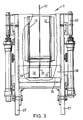
- the coating head shown in Figures 2 and 3 comprises a first body portion 20 and a second body portion 21.
- Each of the first and second body portions comprises two stainless steel side pieces 20′, 21′. Only the side pieces 21′ of the second body portion may be seen in Figure 3.
- the front edges 22′ of the side pieces 22 are curved to match as precisely as possible the curvature of the drum 4 (see Figure 1). Moreover, the surfaces of the side pieces 22 to contact the paper on the drum are highly polished to reduce friction.
- the two body portions 20 and 21 of the head are connected by four pivoting members 23 (only two shown) each of which comprises two parts 23a, 23b, which pivot about pivot points 23′.
- springs 24 between the two body portions 20, 21 are provided.
- a blade 25 is supported in a blade carrier 26 (see Figure 3) at a lower region of the second body portion 21.
- the blade carrier 26 is mounted on plates 26′ guided in arcuate grooves 27 in each side piece of the first body portion 20 is also provided in which the blade carrier 26 may slide thereby controlling the angle of the blade 25.
- the second body portion 21 includes a rear wall 28 having a section with an arcuate surface 29. against this arcuate surface 29, the blade carrier 26 may slide.
- the blade carrier 26 is sealed against surface 29 by a seal 29′ of rubber, or other compressible material.
- a shutter arrangement comprising a shutter 30 hydraulically openable by actuators 30′ (also see Figure 3).
- the shutter 29 and rear wall 28 define a coating reservoir 31.
- the coating reservoir 31 is subdivided by longitudinal baffles 32.
- Baffles 33 are also provided in the lower region of the coating reservoir close to the blade 25. These baffles reduce the tendency of the coating composition to surge as the head 9 moves translationally on the carriageway 8.
- the coating head 9 is brought into contact with the surface of a sheet member, for example, paper, wrapped around the drum 4 (see Figure 1) by actuating the rod 12 to move to the left in Figure 2. Movement of the coating head 9 to the left (i.e. toward the drum 4 - see Figure 1) will take place when a coating cycle is desired and will correspond to the moment at which the coating head 9 is caused to move translationally along the carriageway 8 (see Figure 1).
- the rod 12 is moved a predetermined distance to the left (as shown) in order to urge the first body part 20 toward the surface to be coated, thereby also urging the blade support 26 and the blade 25 toward the surface to be coated.
- the pressure on the blade is controllable by the force with which the rod 12 is urged toward the surface to be coated.
- the second body portion 21 is resiliently mounted on the first body portion 20 by the springs 24.
- the pivoting arms 23 secure the first body portion 20 and second body portion 21, thereby permitting the second body portion 21 to "float" on the first body portion.
- the pivot arms 23 pivot about the points 23′.
- a coating composition is introduced into the coating reservoir 31 and, when a coating cycle is desired, the coating head 9 is urged toward, and into contact with, a sheet member supported on the drum 4 ( Figure 1) which typically is rotatable at a rate to give a surface velocity in the range of from 100 to 1200 m/minute. Simultaneously, the coating head 9 is caused to move translationally along the carriageway 8 and the shutter 29 is opened by actuators 30 a sufficient amount to permit the coating composition to flow out of the coating chamber 31 and be applied to the surface of the paper on the drum 4 by the blade 25.
- the shutter 30 is closed and the front surface 22′ of the coating head is withdrawn from the surface of the paper on the drum 4 and drum 4 is permitted to slow down, whilst the coating composition on the paper is dried. The paper on the drum may then be removed and tested.
Landscapes
- Coating Apparatus (AREA)
- Paper (AREA)
- Application Of Or Painting With Fluid Materials (AREA)
- Non-Silver Salt Photosensitive Materials And Non-Silver Salt Photography (AREA)
- General Preparation And Processing Of Foods (AREA)
- Laminated Bodies (AREA)
- Compositions Of Oxide Ceramics (AREA)
- Analysing Materials By The Use Of Radiation (AREA)
- Medicines Containing Antibodies Or Antigens For Use As Internal Diagnostic Agents (AREA)
Priority Applications (1)
| Application Number | Priority Date | Filing Date | Title |
|---|---|---|---|
| AT89311347T ATE94597T1 (de) | 1988-11-04 | 1989-11-02 | Papierbeschichtung. |
Applications Claiming Priority (2)
| Application Number | Priority Date | Filing Date | Title |
|---|---|---|---|
| GB8825908 | 1988-11-04 | ||
| GB8825908A GB2225261B (en) | 1988-11-04 | 1988-11-04 | Paper coating |
Publications (3)
| Publication Number | Publication Date |
|---|---|
| EP0372710A2 true EP0372710A2 (de) | 1990-06-13 |
| EP0372710A3 EP0372710A3 (de) | 1991-01-09 |
| EP0372710B1 EP0372710B1 (de) | 1993-09-15 |
Family
ID=10646353
Family Applications (1)
| Application Number | Title | Priority Date | Filing Date |
|---|---|---|---|
| EP89311347A Expired - Lifetime EP0372710B1 (de) | 1988-11-04 | 1989-11-02 | Papierbeschichtung |
Country Status (8)
| Country | Link |
|---|---|
| US (1) | US5183691A (de) |
| EP (1) | EP0372710B1 (de) |
| JP (1) | JPH02198660A (de) |
| AT (1) | ATE94597T1 (de) |
| DE (1) | DE68909188T2 (de) |
| ES (1) | ES2043039T3 (de) |
| FI (1) | FI895169A7 (de) |
| GB (1) | GB2225261B (de) |
Families Citing this family (14)
| Publication number | Priority date | Publication date | Assignee | Title |
|---|---|---|---|---|
| DE4228991A1 (de) * | 1992-08-31 | 1994-03-03 | Hoechst Ag | Beschichtungsvorrichtung |
| CN1077845C (zh) | 1994-12-27 | 2002-01-16 | 福特汽车公司 | 布施粘性材料的装置 |
| US5611860A (en) * | 1995-05-17 | 1997-03-18 | Beloit Technologies, Inc. | Hydrostatic shear inducing short dwell coater |
| US5665163A (en) * | 1995-08-22 | 1997-09-09 | Beloit Technologies, Inc. | Film applicator with entrained air removal and surface control |
| US5735957A (en) * | 1995-10-02 | 1998-04-07 | Beloit Technologies, Inc. | Dual chamber film applicator with in-pond overflow |
| US5824155A (en) * | 1995-11-08 | 1998-10-20 | Ford Motor Company | Method and apparatus for dispensing viscous material |
| US5683510A (en) * | 1995-11-29 | 1997-11-04 | Beloit Technologies, Inc. | Coater with air collector |
| FI105167B (fi) * | 1995-12-28 | 2000-06-30 | Valmet Corp | Applikointilaite päällystysaineen applikoimiseksi liikkuvalle alustalle |
| US5700343A (en) * | 1996-01-16 | 1997-12-23 | Reeves Brothers, Inc. | Preparation of cylindrical blanket by spreading of compressible layer |
| US5720816A (en) * | 1996-03-08 | 1998-02-24 | Beloit Technologies, Inc. | Reverse feed film applicator |
| US5759279A (en) * | 1996-12-11 | 1998-06-02 | Macmillan Bloedel Limted | Pilot coater |
| US6217707B1 (en) | 1996-12-31 | 2001-04-17 | Kimberly-Clark Worldwide, Inc. | Controlled coverage additive application |
| US6231719B1 (en) | 1996-12-31 | 2001-05-15 | Kimberly-Clark Worldwide, Inc. | Uncreped throughdried tissue with controlled coverage additive |
| US20060110431A1 (en) * | 2004-11-19 | 2006-05-25 | Kimberly-Clark Worldwide, Inc. | Sheets having alternating areas of relatively high and low lotion add-on in the machine direction |
Family Cites Families (3)
| Publication number | Priority date | Publication date | Assignee | Title |
|---|---|---|---|---|
| GB1032536A (en) * | 1964-05-04 | 1966-06-08 | English Clays Lovering Pochin | Improvements in or relating to the coating of paper and the like |
| US4143187A (en) * | 1977-12-01 | 1979-03-06 | Du Pont Of Canada Limited | Process for coating sheet substrates with thermoplastic polymer |
| US4250211A (en) * | 1978-05-31 | 1981-02-10 | Consolidated Papers, Inc. | Paper coating method and apparatus |
-
1988
- 1988-11-04 GB GB8825908A patent/GB2225261B/en not_active Expired - Lifetime
-
1989
- 1989-10-31 FI FI895169A patent/FI895169A7/fi not_active Application Discontinuation
- 1989-11-02 AT AT89311347T patent/ATE94597T1/de active
- 1989-11-02 ES ES89311347T patent/ES2043039T3/es not_active Expired - Lifetime
- 1989-11-02 EP EP89311347A patent/EP0372710B1/de not_active Expired - Lifetime
- 1989-11-02 DE DE89311347T patent/DE68909188T2/de not_active Expired - Fee Related
- 1989-11-02 JP JP1287246A patent/JPH02198660A/ja active Pending
- 1989-11-03 US US07/431,459 patent/US5183691A/en not_active Expired - Fee Related
Also Published As
| Publication number | Publication date |
|---|---|
| GB8825908D0 (en) | 1988-12-07 |
| GB2225261B (en) | 1992-09-30 |
| ATE94597T1 (de) | 1993-10-15 |
| FI895169A0 (fi) | 1989-10-31 |
| DE68909188T2 (de) | 1994-01-13 |
| EP0372710A3 (de) | 1991-01-09 |
| DE68909188D1 (de) | 1993-10-21 |
| EP0372710B1 (de) | 1993-09-15 |
| ES2043039T3 (es) | 1993-12-16 |
| GB2225261A (en) | 1990-05-30 |
| FI895169A7 (fi) | 1990-05-05 |
| US5183691A (en) | 1993-02-02 |
| JPH02198660A (ja) | 1990-08-07 |
Similar Documents
| Publication | Publication Date | Title |
|---|---|---|
| US5183691A (en) | Paper coating head, apparatus and method | |
| EP0319503B1 (de) | Verfahren und Vorrichtung zum Auftragen und zur Dosierung einer Streichmasse auf ein Trägermaterial in Bewegung | |
| US4440105A (en) | Paper coating apparatus having a replaceable orifice plate | |
| US3486482A (en) | Apparatus for coating traveling webs | |
| US4651672A (en) | Device for coating continuous webs | |
| KR100413008B1 (ko) | 지지롤에의하여안내되는기재에코팅재를도포하는코팅장치 | |
| US4133917A (en) | Method and apparatus for coating a moving web | |
| US4036129A (en) | Squeegee device | |
| US3416943A (en) | Coating of paper and the like | |
| GB2135216A (en) | Web coating apparatus | |
| CA1317808C (en) | Extended nip press belt guide | |
| GB2133322A (en) | Web coasting apparatus | |
| JPH0657332B2 (ja) | 後ブレード紙塗工装置および塗工方法 | |
| FI57800C (fi) | Anordning foer avstrykning av ett oeverskott av oeverdragsmassa | |
| GB1472828A (en) | Paper or cardboard web-making machine comprising apparatus for the smoothness and gloss of the product surface | |
| US4706603A (en) | Coating apparatus with edge protection for paper webs | |
| CA1219168A (en) | Device for metering the ink supply for an offset printing machine | |
| CA2227501C (en) | Rod holder with separate positionable contact elements for rod metering | |
| US4780336A (en) | Doctor blade for paper coater | |
| CA2026063A1 (en) | Short dwell coater apparatus for coating a web with a coating material | |
| US3854441A (en) | Apparatus for applying barrier coating substances to sheet materials | |
| US3711888A (en) | Blade holding apparatus | |
| US3158498A (en) | Method of blade-coating utilizing high angles of flexible blades | |
| EP0629742A1 (de) | Verfahren und Baugruppe zum Laden einer Rakelklinge | |
| CA2224842C (en) | Coating applicator with blade shaping |
Legal Events
| Date | Code | Title | Description |
|---|---|---|---|
| PUAI | Public reference made under article 153(3) epc to a published international application that has entered the european phase |
Free format text: ORIGINAL CODE: 0009012 |
|
| 17P | Request for examination filed |
Effective date: 19891120 |
|
| AK | Designated contracting states |
Kind code of ref document: A2 Designated state(s): AT BE CH DE ES FR GR IT LI LU NL SE |
|
| PUAL | Search report despatched |
Free format text: ORIGINAL CODE: 0009013 |
|
| AK | Designated contracting states |
Kind code of ref document: A3 Designated state(s): AT BE CH DE ES FR GR IT LI LU NL SE |
|
| 17Q | First examination report despatched |
Effective date: 19920515 |
|
| RAP1 | Party data changed (applicant data changed or rights of an application transferred) |
Owner name: ECC INTERNATIONAL LIMITED |
|
| GRAA | (expected) grant |
Free format text: ORIGINAL CODE: 0009210 |
|
| AK | Designated contracting states |
Kind code of ref document: B1 Designated state(s): AT BE CH DE ES FR GR IT LI LU NL SE |
|
| REF | Corresponds to: |
Ref document number: 94597 Country of ref document: AT Date of ref document: 19931015 Kind code of ref document: T |
|
| REF | Corresponds to: |
Ref document number: 68909188 Country of ref document: DE Date of ref document: 19931021 |
|
| ET | Fr: translation filed | ||
| ITF | It: translation for a ep patent filed | ||
| EPTA | Lu: last paid annual fee | ||
| REG | Reference to a national code |
Ref country code: ES Ref legal event code: FG2A Ref document number: 2043039 Country of ref document: ES Kind code of ref document: T3 |
|
| REG | Reference to a national code |
Ref country code: GR Ref legal event code: FG4A Free format text: 3009505 |
|
| PLBE | No opposition filed within time limit |
Free format text: ORIGINAL CODE: 0009261 |
|
| STAA | Information on the status of an ep patent application or granted ep patent |
Free format text: STATUS: NO OPPOSITION FILED WITHIN TIME LIMIT |
|
| 26N | No opposition filed | ||
| EAL | Se: european patent in force in sweden |
Ref document number: 89311347.2 |
|
| PG25 | Lapsed in a contracting state [announced via postgrant information from national office to epo] |
Ref country code: LU Free format text: LAPSE BECAUSE OF NON-PAYMENT OF DUE FEES Effective date: 19981102 |
|
| PGFP | Annual fee paid to national office [announced via postgrant information from national office to epo] |
Ref country code: FR Payment date: 19991011 Year of fee payment: 11 |
|
| PGFP | Annual fee paid to national office [announced via postgrant information from national office to epo] |
Ref country code: AT Payment date: 19991013 Year of fee payment: 11 |
|
| PGFP | Annual fee paid to national office [announced via postgrant information from national office to epo] |
Ref country code: SE Payment date: 19991018 Year of fee payment: 11 Ref country code: CH Payment date: 19991018 Year of fee payment: 11 |
|
| PGFP | Annual fee paid to national office [announced via postgrant information from national office to epo] |
Ref country code: NL Payment date: 19991027 Year of fee payment: 11 |
|
| PGFP | Annual fee paid to national office [announced via postgrant information from national office to epo] |
Ref country code: DE Payment date: 19991028 Year of fee payment: 11 |
|
| PGFP | Annual fee paid to national office [announced via postgrant information from national office to epo] |
Ref country code: ES Payment date: 19991105 Year of fee payment: 11 |
|
| PGFP | Annual fee paid to national office [announced via postgrant information from national office to epo] |
Ref country code: BE Payment date: 19991122 Year of fee payment: 11 |
|
| PGFP | Annual fee paid to national office [announced via postgrant information from national office to epo] |
Ref country code: GR Payment date: 19991124 Year of fee payment: 11 |
|
| PGFP | Annual fee paid to national office [announced via postgrant information from national office to epo] |
Ref country code: LU Payment date: 19991126 Year of fee payment: 11 |
|
| PG25 | Lapsed in a contracting state [announced via postgrant information from national office to epo] |
Ref country code: AT Free format text: LAPSE BECAUSE OF NON-PAYMENT OF DUE FEES Effective date: 20001102 |
|
| PG25 | Lapsed in a contracting state [announced via postgrant information from national office to epo] |
Ref country code: ES Free format text: LAPSE BECAUSE OF NON-PAYMENT OF DUE FEES Effective date: 20001103 |
|
| PG25 | Lapsed in a contracting state [announced via postgrant information from national office to epo] |
Ref country code: SE Free format text: THE PATENT HAS BEEN ANNULLED BY A DECISION OF A NATIONAL AUTHORITY Effective date: 20001129 |
|
| PG25 | Lapsed in a contracting state [announced via postgrant information from national office to epo] |
Ref country code: LI Free format text: LAPSE BECAUSE OF NON-PAYMENT OF DUE FEES Effective date: 20001130 Ref country code: GR Free format text: LAPSE BECAUSE OF NON-PAYMENT OF DUE FEES Effective date: 20001130 Ref country code: CH Free format text: LAPSE BECAUSE OF NON-PAYMENT OF DUE FEES Effective date: 20001130 Ref country code: BE Free format text: LAPSE BECAUSE OF NON-PAYMENT OF DUE FEES Effective date: 20001130 |
|
| BERE | Be: lapsed |
Owner name: ECC INTERNATIONAL LTD Effective date: 20001130 |
|
| PG25 | Lapsed in a contracting state [announced via postgrant information from national office to epo] |
Ref country code: NL Free format text: LAPSE BECAUSE OF NON-PAYMENT OF DUE FEES Effective date: 20010601 |
|
| REG | Reference to a national code |
Ref country code: CH Ref legal event code: PL |
|
| EUG | Se: european patent has lapsed |
Ref document number: 89311347.2 |
|
| PG25 | Lapsed in a contracting state [announced via postgrant information from national office to epo] |
Ref country code: FR Free format text: LAPSE BECAUSE OF NON-PAYMENT OF DUE FEES Effective date: 20010731 |
|
| NLV4 | Nl: lapsed or anulled due to non-payment of the annual fee |
Effective date: 20010601 |
|
| PG25 | Lapsed in a contracting state [announced via postgrant information from national office to epo] |
Ref country code: DE Free format text: LAPSE BECAUSE OF NON-PAYMENT OF DUE FEES Effective date: 20010801 |
|
| REG | Reference to a national code |
Ref country code: FR Ref legal event code: ST |
|
| REG | Reference to a national code |
Ref country code: ES Ref legal event code: FD2A Effective date: 20011214 |
|
| PG25 | Lapsed in a contracting state [announced via postgrant information from national office to epo] |
Ref country code: IT Free format text: LAPSE BECAUSE OF NON-PAYMENT OF DUE FEES Effective date: 20051102 |