EP0372844A2 - Méthode de commande d'une imprimante - Google Patents
Méthode de commande d'une imprimante Download PDFInfo
- Publication number
- EP0372844A2 EP0372844A2 EP89312546A EP89312546A EP0372844A2 EP 0372844 A2 EP0372844 A2 EP 0372844A2 EP 89312546 A EP89312546 A EP 89312546A EP 89312546 A EP89312546 A EP 89312546A EP 0372844 A2 EP0372844 A2 EP 0372844A2
- Authority
- EP
- European Patent Office
- Prior art keywords
- carriage
- printer
- routine
- control system
- indicated
- Prior art date
- Legal status (The legal status is an assumption and is not a legal conclusion. Google has not performed a legal analysis and makes no representation as to the accuracy of the status listed.)
- Granted
Links
Images


Classifications
-
- B—PERFORMING OPERATIONS; TRANSPORTING
- B41—PRINTING; LINING MACHINES; TYPEWRITERS; STAMPS
- B41J—TYPEWRITERS; SELECTIVE PRINTING MECHANISMS, i.e. MECHANISMS PRINTING OTHERWISE THAN FROM A FORME; CORRECTION OF TYPOGRAPHICAL ERRORS
- B41J19/00—Character- or line-spacing mechanisms
- B41J19/18—Character-spacing or back-spacing mechanisms; Carriage return or release devices therefor
- B41J19/20—Positive-feed character-spacing mechanisms
- B41J19/202—Drive control means for carriage movement
- B41J19/205—Position or speed detectors therefor
- B41J19/207—Encoding along a bar
Definitions
- the present invention relates to a control system for a printer and more particularly to a control system for controlling the movement of a print head mounted on a carriage in the printer.
- a control system for controlling the movement of a print head on a carriage in a printer is described in U.S Patent No. 4,338,035.
- the position of the carriage is determined by means of a carriage position detector mounted on the carriage with its detecting part astride a slitted plate at the level of the slits. Movement of the carriage along a guide rail causes the carriage position detector to scan the slits in the slitted plate to provide position pulses and direction pulses which are fed to a position counter.
- the data from the position counter is utilized to control a drive motor for driving the carriage along the guide rail.
- One of the disadvantages of the above known control system is that there is no provision for verifying whether or not the absence of position pulses, indicating non-motion of the carriage, is due to the carriage being in a predetermined home position or due to a jam condition.
- the jam condition can be caused for example by failure of, or external interference with, the carriage drive motor, driving mechanism or the print head.
- An object of the present invention is to provide a control system for controlling the movement of a print head on a carriage in a printer whereby means are provided for verifying that a predetermined or home position of the carriage has been reached and also for determining a jam condition thereof.
- the present invention provides a control system for controlling the movement of a print head mounted on a carriage in a printer including drive means for moving said carriage in a reciprocal manner along a rectilinear guide path, an elongate member having a plurality of spaced openings therealong and secured to the frame of said printer so as to be fixed relative to said guide path and detector means secured to said carriage and positioned to sense said openings and to provide output signals when said openings are scanned by said detector means, characterized in that said detector means is arranged to generate output signals of first and second values dependent on whether or not said detector means is sensing one of said openings, a change in said output signals between said values defining a signal transition and the time interval between consecutive signal transitions defining a signal transition period, and control means for determining whether said carriage has stopped in a correct predetermined position along said guide path, said control means being responsive to said output signals for moving said carriage in a predetermined direction for verifying said predetermined position of said carriage dependent upon a pattern of signal transition periods monitored during said movement
- the printer to be described in accordance with an embodiment of the present invention is a multi-function type that can accommodate a receipt, a journal and a slip or form which form consists of one or more parts.
- the printer can be set in one of five different modes of operation which include printing a journal only, printing a receipt in one of five different modes of operation which include printing a journal only, printing a receipt only, printing a receipt and a journal, printing a slip or form only, or printing a slip or form and a journal.
- the journal and the receipt can accommodate 42 columns of printing and the slip or form can accommodate 46 columns of printing.
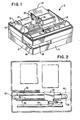
- Fig. 1 shows a perspective view of a printer 12 having a front portion 14, a right side 16, a left side 18, and a rear portion 20.
- a wire matrix print head 22 is moved in a side-to-side manner by suitable motor drive means (Fig. 3) located at the right front corner of the printer 12.
- a journal station or module 24 is provided at the right side of the printer and includes a supply roll 26 of journal paper that is guided past the journal print station platen 28 and is rewound on a take-up roller 30 by a step-type drive motor (not shown).
- a receipt station or module 32 is provided at the left side of the printer 12 and includes a supply roll 34 of receipt paper that is guided past the receipt print station platen 36 and is driven by a step-type drive motor (not shown).
- the journal station 24 and the receipt station 32 are separated by a preferred number (19) of character spaces.
- a ribbon cassette (not shown) of the operator-changeable type is positioned to the rear of the print head 22 (toward the viewer of the illustration in Fig. 1) and the ribbon is driven in one direction from right to left in a path between the front portion of the print head 22 and the record media (journal, receipt or slip).
- a slot 40 is provided at the left front side of the printer 12 for insertion of a slip 38 which can be inserted from the front of the printer 12 or from the side thereof in a path in front of the receipt paper at the receipt station 32.
- a heat sink 42 is provided for the print head 22 to dissipate heat therefrom.
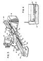
- Figs. 2 and 3 illustrate the drive mechanism in accordance with an embodiment of the present invention wherein an endless toothed belt 46, driven by the print head carriage motor drive means in the form of a stepper motor 48, is trained around a first or motor pulley 50.
- the motor pulley 50 is secured to and extends upwardly from the stepper motor 48.
- the endless toothed belt 46 is trained around a second pulley 52 at the left side of the printer 12.
- a print head carriage 54 is secured by means of a curved or arcuate connector to the timing belt 46 to move the carriage 54 back and forth across the printer in bi-directional printing operations.
- the carriage 54 supports the print head 22 in precise position for printing on the journal, the receipt, or the slip, as the case may be.
- the carriage 54 is supported by and rides on rails 56 and 58 (Fig. 2) by means of bearings 60 and 62 (Fig. 3).
- the carriage 54 is molded from conductive plastic for satisfactory EDS (electrostatic discharge) performance and for static
- the carriage 54 includes a printed circuit board 64 as a part thereof which is connected to a ribbon-style cable 66.
- the cable 66 is connected to power and control devices in the form of circuit boards (not shown) coupled to printer control means or a printer controller providing a specific control program for operating the printer 12.
- the solenoids (not shown) for operating the wires of the print head 22 are connected to the printed circuit board 64 and to the cable 66.
- a timing strip 68 of elongated structure and made of plastic material is molded as an integral part of the frame portion 69 of the printer 12. This construction, as shown in Fig. 4, provides that the timing strip 68 is secured and fixed in one position on the printer 12 and is not subject to movement or to adjustment.
- the timing strip 68 includes a lower solid portion 70 and a plurality of slots 72 facing upwardly and extending substantially along the length of the timing strip 68.
- An optical sensor 74 of the light emitting diode and phototransistor type is secured to the underside of the carriage 54 and straddles the timing strip 68. Output signals from the optical sensor 74 are transmitted therefrom to the ribbon cable 66 and to the printer controller.
- the timing strip 68/optical sensor 74 arrangement and the program associated therewith are effective to place the print head 22 and carriage 54 at the home position and also to detect a jam condition of the print head drive motor 48 or the carriage 54.
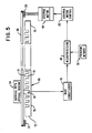
- Fig. 5 is a block diagram of the pertinent parts of the printer.
- the stepper motor 48 is shown as being coupled to the pulley 50, which drives the endless belt 46, which belt is trained around the pulley 52.
- the timing strip 68 includes the lower portion 70 that is formed integral with the frame portion 69 of the printer 12 (Fig. 4) and also includes the plurality of slots 72 therein.
- the carriage 54 has the optical sensor 74 secured thereto with the sensor 74 being coupled to block 76 which represents an arrangement in structure that includes a wave conditioner.
- the wave conditioner 76 receives an input analog signal, sinusoidal in form, from the optical sensor 74 and converts the input analog signal into a digital square wave output signal.
- the output signal of the wave conditioner 76 is input to a microprocessor 80.
- a program memory 78 is coupled to the microprocessor 80 and the program memory in conjunction with the output signal of the wave conditioner 76 instructs the microprocessor 80 to produce sequential control signals to a stepper motor control 82 for operation of the stepper motor 48.
- the stepper motor control 82 contains the necessary power and control circuitry to maintain desired phase ampacity levels during sequential stepping operation of the stepper motor 48.
- the stepper motor control 82 provides the desired and necessary control for both speed and direction of rotation of the stepper motor 48 for driving the carriage 54 and the print head 22 in transverse manner on the printer 12 in bi-directional printing operations. Portions of the program memory 78 pertaining to the carriage drive system are illustrated in the flow charts of Figs. 6-12, inclusive, and described herein.
- the printer controller is a stored program in the program memory 78, executed by the microprocessor 80, to provide specific control signals for operating the printer 12, in response to commands received through the communications interface.
- the printer controller uses the square wave output of the timing strip 68 and optical sensor 74 arrangement to perform two functions:
- the first function is to place the printhead 22 in a known location called the home position, or home, for the purpose of correctly positioning subsequent print lines on the paper.
- the printer controller orients the printhead 22 to home when the printer 12 is turned on, and reorients it at certain other times during printer operation, such as when an operator has manually moved the printhead 22 in order to change the ribbon.
- either the left side of the printer 12 or the right side of the printer could be the home position, however, it is preferred to call the left side of the printer the home position.
- the second function is to detect a jam condition while the carriage is moving to print or to cut paper.
- a jam condition can be caused by failure of, or external interference with, the carriage stepper motor 48, either of the pulleys 50 or 52, the endless toothed belt 46, the printhead 22, and other matters or conditions.
- the square wave output of the timing strip/optical sensor arrangement is such that the printer controller senses a low level of the square wave while the optical sensor 74 is passing over the slots 72 in the timing strip 68. In complement, the printer controller senses a high level of the square wave while the optical sensor 74 is passing over the portions 71 of the timing strip 68 between the slots 72 and at both ends 73, 75 of the timing strip.
- each slot 72 in the timing strip 68 is equal to the distance the carriage 54 moves in ten steps of the carriage stepper motor 48.
- the width of each portion 71 of the timing strip between two slots is equal to twice that of each slot 72, or the distance the carriage moves in 20 steps of the carriage stepper motor 48.
- the width of those portions of the timing strip 68 at each end, the portion 73 to the left of the first slot, and the portion 75 to the right of the last slot, is greater than the distance the carriage moves in 30 steps of the carriage stepper motor 48.
- the printer controller moves the carriage drive motor 48 one step every 500 microseconds to achieve the desired print speed. It should be noted that steps less often than 500 microseconds would result in a slower print speed while steps more often than 500 microseconds would result in a faster print speed.
- the printer controller uses the information provided by the square wave output of the timing strip/optical sensor arrangement to place the printhead 22 in a known location, called home in the following manner.
- the printer controller senses a low level of the square wave for ten carriage motor steps, followed by a high level of the square wave for 20 carriage motor steps, followed by a low level of the square wave for ten carriage motor steps, etc., followed finally by a high level of the square wave for more than 30 steps of the carriage stepper motor 48. At this point, the printhead is at the tentative home position.
- the printer controller To distinguish between home and a jam condition while establishing home, the printer controller next verifies the home position by first moving the carriage 54 to the right a certain distance out of home, and then moving the carriage 54 to the left, back into home. If the printer controller senses the correct pattern of transitions of the square wave output of the timing strip 68 at the correct time intervals, then home is established. If the printer controller senses an incorrect pattern of transitions of the timing strip 68, or an incorrect time interval between transitions, the printer controller recognizes that the printer is in a jam condition. The printer controller then stops trying to move the carriage 54 and asserts a fault condition to the communications interface.
- the printer controller uses the information provided by the square wave output of the timing strip/optical sensor arrangement to detect a jam condition in the following manner.
- the printer controller senses high-to-low transitions repeatedly, at a time interval equal to 30 carriage motor steps. In the current design, if the carriage 54 is moving to print or to cut paper, and a time interval equal to 50 carriage motor steps goes by without the printer controller sensing at least one high-to-low transition, the printer controller recognizes that the carriage 54 is no longer moving and that the printer 12 is in a jam condition. The printer controller then stops trying to move the carriage 54 and asserts a fault condition to the communications interface.
- the time interval equal to 50 carriage motor steps used in this design to detect a jam condition could be shorter for greater sensitivity to a jam condition or longer for less sensitivity to a jam condition.
- Figs. 6-12, inclusive, constitute a set of flow charts describing the printer controller home algorithms in more detail.
- Fig. 6 is a flow chart of the printer controller carriage home routine, as indicated by the title block 84.
- the printer controller carriage home routine consists of four segments or steps carried out in sequence.
- the first segment is initialization, as indicated by step 86.
- the second segment is a routine to establish the tentative home position, as indicated by step 88.
- Step 88 is described in more detail in Fig. 7.
- the third segment is a routine to verify the home position, as indicated by step 90.
- Step 90 is described in more detail in Figs. 8 and 9.
- the fourth segment is finalization of the printhead in the home position, as indicated by step 92.
- Fig. 7 is a flow chart of the printer controller routine to establish the tentative home position, as indicated by the title block 94.
- the printer controller routine to establish the tentative home position consists of eight segments or steps carried out in sequence.
- the first segment is initialization, as indicated by step 96.
- the second segment is a routine to begin moving the carriage 54 to the left and accelerating it to print speed, as indicated by step 98.
- the third segment is a routine which examines the square wave output of the timing strip 68 at the moment in time at which the carriage 54 reaches full acceleration to print speed, as indicated by step 100. If the printer controller is sensing a low level of the square wave, program control passes to step 102. If the printer controller is sensing a high level of the square wave, program control skips step 102 and passes to step 104.
- the fourth segment is a routine to look for a low-to-high transition of the square wave, or a jam condition, as indicated by step 102. If a transition occurs in step 102, then program control returns to step 104. If a jam condition is detected in step 102, then program control does not return to this routine. Step 102 is described in more detail in Fig. 10.
- the fifth segment is a routine to look for a high-to-low transition of the square wave, or the home position, as indicated by step 104.
- Step 104 is described in more detail in Fig. 11.
- the sixth segment as indicated in step 106, makes a decision based on the outcome of step 104. If a transition occurred in step 104, then program control passes from step 106 back to step 102. If a transition did not occur in step 104, then program control passes to step 108.
- Program control continues to loop through steps 102, 104 and 106 until no high-to-low transition occurs in step 104.
- the seventh segment is a routine to decelerate the carriage 54 at the tentative home position, as indicated in step 108.
- the eighth segment as indicated by step 110, returns program control to the caller of this routine, step 88.
- Figs. 8 and 9 constitute a flow chart of the printer controller routine to verify the home position, as indicated by the title block 112.
- the printer controller routine to verify the home position consists of twelve segments carried out in sequence.
- the first segment is initialization, as indicated by step 114.
- the second segment is a routine to begin moving the carriage to the right and accelerating it to print speed, as indicated by step 116.
- the third segment is a routine to look for a high-to-low transition of the square wave, or a jam condition, as indicated by step 118. If a transition occurs in step 118, then program control returns to step 120. If a jam condition is detected in step 118, then program control does not return to this routine. Step 118 is described in more detail in Fig. 12.
- the fourth segnent is a routine to look for a low-to-high transition of the square wave, or a jam condition, as indicated by step 120. If a transition occurs in step 120, then program control returns to step 122. If a jam condition is detected in step 120, then program control does not return to this routine. Step 120 is described in more detail in Fig. 10.
- the fifth segment is a routine to look for a high-to-low transition of the square wave, or a jam condition, as indicated by step 122. If a transition occurs in step 122, then program control returns to step 124. If a jam condition is detected in step 122, then program control does not return to this routine. Step 122 is described in more detail in Fig. 12.
- the sixth segment is a routine to decelerate the carriage, as indicated by step 124.
- Step 126 indicates that the flow chart of the printer controller routine to verify the home position is continued in Fig. 9.
- the seventh segment is a routine to begin moving the carriage to the left and accelerating it to print speed, as indicated by step 128.
- the eighth segnent is a routine to look for a low-to-high transition of the square wave, or a jam condition, as indicated by step 130. If a transition occurs in step 130, then program control returns to step 132. If a jam condition is detected in step 130, then program control does not return to this routine. Step 130 is described in more detail in Fig. 10.
- the ninth segment is a routine to look for a high-to-low transition of the square wave, or a jam condition, as indicated by step 132. If a transition occurs in step 132, then program control returns to step 134. If a jam condition is detected in 132, then program control does not return to this routine. Step 132 is described in more detail in Fig. 12.
- the tenth segment is a routine to continue moving the carriage 54 left for 33 more carriage motor steps to position the carriage 54 for printing, as indicated by step 134.
- a different number of carriage motor steps could be used without changing the intent of the design.
- the eleventh segment is a routine to decelerate the carriage, as indicated by step 136.
- the twelfth segment as indicated by step 138, returns program control to the caller of this routine, step 90.
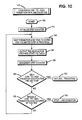
- Fig. 10 is a flow chart of the printer controller routine to look for a low-to-high transition of the square wave, or a jam condition, as indicated by the title block 140.
- the printer controller routine to look for a low-to-high transition of the square wave, or a jam condition consists of nine segments carried out in sequence.
- the first segment is initialization, as indicated by step 142.
- the second segment is a routine to initialize a carriage motor step counter, as indicated in step 144. This carriage motor step counter is used to limit the number of times program control loops through the main part of this routine.
- the third segment is a routine to wait for the motor step time to expire for the motor step in progress, as indicated in step 146.
- the fourth segment is a routine to output the next motor step and start its timer, as indicated in step 148.
- the fifth segment is a routine to increment the carriage motor step counter, as indicated in step 150.
- the sixth segment is a routine which inquires if a low-to-high transition occurred during the time of the last carriage motor step. If a low-to-high transition did occur, then program control passes to step 154, the seventh segment, which then returns to the caller of this routine, either to step 102 or to step 120 or to step 130. If a low-to-high transition did not occur, then program control passes to step 156.
- the eighth segment is a routine which inquires if a low-to-high transition should have occurred by this time, based on the current value of the carriage motor step counter. If a low-to-high transition should not have occurred yet, then program control passes back to 146. If a low-to-high transition should have occurred by this time, then program control passes to step 158, the ninth segment, which then exits to the printer controller jam condition routine.
- Fig. 11 is a flow chart of the printer controller routine to look for a high-to-low transition of the square wave, or the home position, as indicated by the title block 160.
- the printer controller routine to look for a high-to-low transition of the square wave, or the home position consists of nine segments carried out in sequence.
- the first segment is initialization, as indicated by step 162.
- the second segment is a routine to initialize a carriage motor step counter, as indicated in step 164.
- This carriage motor step counter is used to limit the number of times program control loops through the main part of this routine.
- the third segment is a routine to wait for the motor step time to expire for the motor step in progress, as indicated in step 166.
- the fourth segment is a routine to output the next motor step and start its timer, as indicated in step 168.
- the fifth segment is a routine to increment the carriage motor step counter, as indicated in step 170.
- the sixth segment is a routine which inquires if a high-to-low transition occurred during the time of the last carriage motor step. If a high-to-low transition did occur, then program control passes to step 174, the seventh segment, which then returns to the caller of this routine, step 104. If a high-to-low transition did not occur, then program control passes to step 176.
- the eighth segment is a routine which inquires if a high-to-low transition should have occurred by this time, based on the current value of the carriage motor step counter. If a high-to-low transition should not have occurred yet, then program control passes back to step 166. If a high-to-low transition should have occurred by this time, then the carriage may be at the home position and program control passes to step 178, the ninth segment, which then returns to the caller of this routine, step 104.
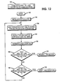
- Fig. 12 is a flow chart of the printer controller routine to look for a high-to-low transition of the square wave, or a jam condition, as indicated by the title block 180.
- the printer controller routine to look for a high-to-low transition of the square wave, or a jam condition consists of nine segments carried out in sequence.
- Tbe first segment is initialization, as indicated by step 182.
- the second segment is a routine to initialize a carriage motor step counter, as indicated in step 184.
- This carriage motor step counter is used to limit the number of times program control loops through the main part of this routine.
- the third segment is a routine to wait for the motor step time to expire for the motor step in progress, as indicated in step 186.
- the fourth segment is a routine to output the next motor step and start its timer, as indicated in step 188.
- the fifth segment is a routine to increment the carriage motor step counter, as indicated in step 190.
- the sixth segment is a routine which inquires if a high-to-low transition occurred during the time of the last carriage motor step. If a high-to-low transition did occur, then program control passes to step 194, the seventh segment, which then returns to the caller of this routine, either to step 118 or to step 122 or to step 132. If a high-to-low transition did not occur, then program control passes to step 196.
- the eighth segment is a routine which inquires if a high-to-low transition should have occurred by this time, based on the current value of the carriage motor step counter. If a high-to-low transition should not have occurred yet, then program control passes back to step 186. If a high-to-low transition should have occurred by this time, then program control passes to step 198, the ninth segment, which then exits to the printer controller jam condition routine.
- the timing strip output signals for normal carriage movement in printing operations provide repeated high-to-low or repeated low-to-high transitions.
- a preferred timing strip period is 15 milliseconds wherein a high level is sensed for 10 milliseconds, a low level is sensed for 5 milliseconds, a high level for 10 milliseconds, and a low level for 5 milliseconds in repeated sequence.
Landscapes
- Character Spaces And Line Spaces In Printers (AREA)
- Accessory Devices And Overall Control Thereof (AREA)
Applications Claiming Priority (2)
| Application Number | Priority Date | Filing Date | Title |
|---|---|---|---|
| US27886688A | 1988-12-02 | 1988-12-02 | |
| US278866 | 1988-12-02 |
Publications (3)
| Publication Number | Publication Date |
|---|---|
| EP0372844A2 true EP0372844A2 (fr) | 1990-06-13 |
| EP0372844A3 EP0372844A3 (en) | 1990-11-28 |
| EP0372844B1 EP0372844B1 (fr) | 1993-09-15 |
Family
ID=23066707
Family Applications (1)
| Application Number | Title | Priority Date | Filing Date |
|---|---|---|---|
| EP19890312546 Expired - Lifetime EP0372844B1 (fr) | 1988-12-02 | 1989-12-01 | Méthode de commande d'une imprimante |
Country Status (3)
| Country | Link |
|---|---|
| EP (1) | EP0372844B1 (fr) |
| JP (1) | JP2850142B2 (fr) |
| DE (1) | DE68909189T2 (fr) |
Cited By (6)
| Publication number | Priority date | Publication date | Assignee | Title |
|---|---|---|---|---|
| EP0514038A3 (en) * | 1991-05-16 | 1993-01-20 | Mitsubishi Steel Mfg. Co., Ltd. | Printing machine |
| EP0500116A3 (en) * | 1991-02-22 | 1993-05-26 | Tokyo Electric Co., Ltd. | Position detecting apparatus |
| EP0585881A3 (fr) * | 1992-08-31 | 1994-12-07 | Canon Kk | Imprimante en série. |
| EP0650844A3 (fr) * | 1993-11-01 | 1996-04-03 | Hewlett Packard Co | Imprimantes de type navette et méthodes pour sa mise en oeuvre. |
| RU2149762C1 (ru) * | 1999-05-18 | 2000-05-27 | Открытое акционерное общество "Ленполиграфмаш" | Печатающее устройство |
| GB2356600B (en) * | 1999-11-16 | 2003-04-30 | Agilent Technologies Inc | Optical navigation system and method |
Families Citing this family (4)
| Publication number | Priority date | Publication date | Assignee | Title |
|---|---|---|---|---|
| US7699435B2 (en) | 2005-02-15 | 2010-04-20 | Hewlett-Packard Development Company, L.P. | Uniquely spaced markings |
| US7654629B2 (en) | 2006-07-27 | 2010-02-02 | Hewlett-Packard Development Company, L.P. | Carriage positioning |
| JP2010029834A (ja) * | 2008-07-31 | 2010-02-12 | Mitsuboshi Belting Ltd | キャリッジ搬送用ベルト |
| JP6107324B2 (ja) * | 2013-03-29 | 2017-04-05 | ブラザー工業株式会社 | 画像形成システム |
Family Cites Families (3)
| Publication number | Priority date | Publication date | Assignee | Title |
|---|---|---|---|---|
| US4338035A (en) * | 1980-08-11 | 1982-07-06 | Canon Kabushiki Kaisha | Printer |
| US4517503A (en) * | 1983-09-27 | 1985-05-14 | Mechatron Systems, Inc. | Method and apparatus for normalizing the speed of an element positionable by a servomechanism |
| US4518272A (en) * | 1984-01-12 | 1985-05-21 | Ncr Corporation | Position indicator means for a high speed printer or the like |
-
1989
- 1989-11-29 JP JP1307785A patent/JP2850142B2/ja not_active Expired - Fee Related
- 1989-12-01 DE DE1989609189 patent/DE68909189T2/de not_active Expired - Fee Related
- 1989-12-01 EP EP19890312546 patent/EP0372844B1/fr not_active Expired - Lifetime
Cited By (9)
| Publication number | Priority date | Publication date | Assignee | Title |
|---|---|---|---|---|
| EP0500116A3 (en) * | 1991-02-22 | 1993-05-26 | Tokyo Electric Co., Ltd. | Position detecting apparatus |
| US5331680A (en) * | 1991-02-22 | 1994-07-19 | Tokyo Electric Co., Ltd. | Position detecting apparatus |
| EP0514038A3 (en) * | 1991-05-16 | 1993-01-20 | Mitsubishi Steel Mfg. Co., Ltd. | Printing machine |
| EP0585881A3 (fr) * | 1992-08-31 | 1994-12-07 | Canon Kk | Imprimante en série. |
| US5427461A (en) * | 1992-08-31 | 1995-06-27 | Canon Kabushiki Kaisha | Serial printer with carriage position control |
| EP0650844A3 (fr) * | 1993-11-01 | 1996-04-03 | Hewlett Packard Co | Imprimantes de type navette et méthodes pour sa mise en oeuvre. |
| RU2149762C1 (ru) * | 1999-05-18 | 2000-05-27 | Открытое акционерное общество "Ленполиграфмаш" | Печатающее устройство |
| GB2356600B (en) * | 1999-11-16 | 2003-04-30 | Agilent Technologies Inc | Optical navigation system and method |
| US6568777B1 (en) | 1999-11-16 | 2003-05-27 | Agilent Technologies, Inc. | Optical navigation system and method |
Also Published As
| Publication number | Publication date |
|---|---|
| JPH02179779A (ja) | 1990-07-12 |
| DE68909189D1 (de) | 1993-10-21 |
| EP0372844B1 (fr) | 1993-09-15 |
| EP0372844A3 (en) | 1990-11-28 |
| DE68909189T2 (de) | 1994-04-28 |
| JP2850142B2 (ja) | 1999-01-27 |
Similar Documents
| Publication | Publication Date | Title |
|---|---|---|
| US5074690A (en) | Print head carriage homing system | |
| EP0372844B1 (fr) | Méthode de commande d'une imprimante | |
| US4261039A (en) | Microprocessor controlled positioning system | |
| US5075609A (en) | Recording apparatus | |
| US4179223A (en) | Printer center sensing mechanism | |
| EP0634279B1 (fr) | Appareil d'impression et procédé | |
| US4024447A (en) | Stepping motor driving apparatus | |
| US5926192A (en) | Print control system | |
| US20250242616A1 (en) | Carriage apparatus, printing apparatus, and control method thereof | |
| GB2127193A (en) | Control system for a serial printer | |
| KR920008009B1 (ko) | 라인 프린터 장치 | |
| JPS61233569A (ja) | 印字装置 | |
| EP0500116B1 (fr) | Appareil de détection de position | |
| EP0393158B1 (fr) | Appareil de commande d'alimentation de ruban | |
| EP1024016B1 (fr) | Alignement des imprimés | |
| EP0508784B1 (fr) | Imprimante avec plusieurs systèmes d'impression | |
| US4669897A (en) | Dot matrix printer capable of varying character size | |
| US4185930A (en) | Print position control in a printer including a printer head mounted on a traveling carriage | |
| KR880002267B1 (ko) | 프린터 제어장치 및 그방식 | |
| EP0168474B1 (fr) | Organe indicateur de position pour un dispositif commande electriquement tel qu'une imprimante | |
| KR100687686B1 (ko) | 인쇄 도트 어긋남 보정 제어 방법 및 그 인쇄 장치 | |
| US5033889A (en) | Open loop carriage control for dot-matrix printer using tables | |
| JPH01202462A (ja) | シリアルプリンタの印字制御装置 | |
| US5147143A (en) | Printer carriage homing mechanism | |
| US5250885A (en) | Servo motor control device |
Legal Events
| Date | Code | Title | Description |
|---|---|---|---|
| PUAI | Public reference made under article 153(3) epc to a published international application that has entered the european phase |
Free format text: ORIGINAL CODE: 0009012 |
|
| AK | Designated contracting states |
Kind code of ref document: A2 Designated state(s): DE FR GB |
|
| PUAL | Search report despatched |
Free format text: ORIGINAL CODE: 0009013 |
|
| AK | Designated contracting states |
Kind code of ref document: A3 Designated state(s): DE FR GB |
|
| 17P | Request for examination filed |
Effective date: 19910525 |
|
| 17Q | First examination report despatched |
Effective date: 19930218 |
|
| RAP1 | Party data changed (applicant data changed or rights of an application transferred) |
Owner name: NCR INTERNATIONAL INC. |
|
| GRAA | (expected) grant |
Free format text: ORIGINAL CODE: 0009210 |
|
| AK | Designated contracting states |
Kind code of ref document: B1 Designated state(s): DE FR GB |
|
| REF | Corresponds to: |
Ref document number: 68909189 Country of ref document: DE Date of ref document: 19931021 |
|
| ET | Fr: translation filed | ||
| PLBE | No opposition filed within time limit |
Free format text: ORIGINAL CODE: 0009261 |
|
| STAA | Information on the status of an ep patent application or granted ep patent |
Free format text: STATUS: NO OPPOSITION FILED WITHIN TIME LIMIT |
|
| 26N | No opposition filed | ||
| REG | Reference to a national code |
Ref country code: GB Ref legal event code: IF02 |
|
| PGFP | Annual fee paid to national office [announced via postgrant information from national office to epo] |
Ref country code: GB Payment date: 20021003 Year of fee payment: 14 |
|
| PGFP | Annual fee paid to national office [announced via postgrant information from national office to epo] |
Ref country code: FR Payment date: 20021029 Year of fee payment: 14 |
|
| REG | Reference to a national code |
Ref country code: GB Ref legal event code: 746 Effective date: 20021024 |
|
| PGFP | Annual fee paid to national office [announced via postgrant information from national office to epo] |
Ref country code: DE Payment date: 20021209 Year of fee payment: 14 |
|
| REG | Reference to a national code |
Ref country code: FR Ref legal event code: D6 |
|
| PG25 | Lapsed in a contracting state [announced via postgrant information from national office to epo] |
Ref country code: GB Free format text: LAPSE BECAUSE OF NON-PAYMENT OF DUE FEES Effective date: 20031201 |
|
| PG25 | Lapsed in a contracting state [announced via postgrant information from national office to epo] |
Ref country code: DE Free format text: LAPSE BECAUSE OF NON-PAYMENT OF DUE FEES Effective date: 20040701 |
|
| GBPC | Gb: european patent ceased through non-payment of renewal fee |
Effective date: 20031201 |
|
| PG25 | Lapsed in a contracting state [announced via postgrant information from national office to epo] |
Ref country code: FR Free format text: LAPSE BECAUSE OF NON-PAYMENT OF DUE FEES Effective date: 20040831 |
|
| REG | Reference to a national code |
Ref country code: FR Ref legal event code: ST |