EP0372901B1 - Système d'automatisme pour atteindre la force à baisser pour des ouvreurs à dent - Google Patents
Système d'automatisme pour atteindre la force à baisser pour des ouvreurs à dent Download PDFInfo
- Publication number
- EP0372901B1 EP0372901B1 EP89312659A EP89312659A EP0372901B1 EP 0372901 B1 EP0372901 B1 EP 0372901B1 EP 89312659 A EP89312659 A EP 89312659A EP 89312659 A EP89312659 A EP 89312659A EP 0372901 B1 EP0372901 B1 EP 0372901B1
- Authority
- EP
- European Patent Office
- Prior art keywords
- soil
- gauge
- soil penetrating
- penetrating member
- opener
- Prior art date
- Legal status (The legal status is an assumption and is not a legal conclusion. Google has not performed a legal analysis and makes no representation as to the accuracy of the status listed.)
- Expired - Lifetime
Links
- 239000002689 soil Substances 0.000 claims abstract description 91
- 230000000149 penetrating effect Effects 0.000 claims abstract description 48
- 238000000429 assembly Methods 0.000 claims abstract description 19
- 230000000712 assembly Effects 0.000 claims abstract description 18
- 230000035515 penetration Effects 0.000 claims description 10
- 238000000034 method Methods 0.000 claims description 4
- 230000004044 response Effects 0.000 claims description 4
- 238000002955 isolation Methods 0.000 abstract description 2
- 241001125862 Tinca tinca Species 0.000 abstract 1
- 238000010899 nucleation Methods 0.000 description 10
- 238000006073 displacement reaction Methods 0.000 description 6
- 230000008859 change Effects 0.000 description 5
- 239000003337 fertilizer Substances 0.000 description 5
- 238000012544 monitoring process Methods 0.000 description 4
- 238000003971 tillage Methods 0.000 description 4
- 230000007423 decrease Effects 0.000 description 3
- 238000005553 drilling Methods 0.000 description 2
- 230000000694 effects Effects 0.000 description 2
- 238000005096 rolling process Methods 0.000 description 2
- 239000002002 slurry Substances 0.000 description 2
- 239000004809 Teflon Substances 0.000 description 1
- 229920006362 Teflon® Polymers 0.000 description 1
- 230000009471 action Effects 0.000 description 1
- 239000000872 buffer Substances 0.000 description 1
- 239000000969 carrier Substances 0.000 description 1
- 238000006243 chemical reaction Methods 0.000 description 1
- 230000006835 compression Effects 0.000 description 1
- 238000007906 compression Methods 0.000 description 1
- 230000001276 controlling effect Effects 0.000 description 1
- 230000001419 dependent effect Effects 0.000 description 1
- 238000007599 discharging Methods 0.000 description 1
- 239000000428 dust Substances 0.000 description 1
- 238000001914 filtration Methods 0.000 description 1
- 239000012530 fluid Substances 0.000 description 1
- 238000009432 framing Methods 0.000 description 1
- 230000005484 gravity Effects 0.000 description 1
- 239000007788 liquid Substances 0.000 description 1
- 230000014759 maintenance of location Effects 0.000 description 1
- 239000000463 material Substances 0.000 description 1
- 230000007246 mechanism Effects 0.000 description 1
- 239000011236 particulate material Substances 0.000 description 1
- 230000008569 process Effects 0.000 description 1
- 230000001105 regulatory effect Effects 0.000 description 1
- 230000035945 sensitivity Effects 0.000 description 1
- 239000004575 stone Substances 0.000 description 1
Images


Classifications
-
- A—HUMAN NECESSITIES
- A01—AGRICULTURE; FORESTRY; ANIMAL HUSBANDRY; HUNTING; TRAPPING; FISHING
- A01C—PLANTING; SOWING; FERTILISING
- A01C5/00—Making or covering furrows or holes for sowing, planting or manuring
- A01C5/06—Machines for making or covering drills or furrows for sowing or planting
-
- A—HUMAN NECESSITIES
- A01—AGRICULTURE; FORESTRY; ANIMAL HUSBANDRY; HUNTING; TRAPPING; FISHING
- A01C—PLANTING; SOWING; FERTILISING
- A01C7/00—Sowing
- A01C7/20—Parts of seeders for conducting and depositing seed
- A01C7/201—Mounting of the seeding tools
- A01C7/205—Mounting of the seeding tools comprising pressure regulation means
Definitions
- the present invention relates to improved apparatus and methods whereby a seed drill, slurry injector, or other ground penetrative means (hereinafter simply referred to as “the ground penetrating member”) can be maintained at a predetermined and substantially constant depth.
- a ground penetrating member where constant depth is required is a seed drill.
- seed drills take the form of a variety of assemblies, sub-assemblies (hereafter "assemblies”) carried from a frame or supporting the weight of a frame that is towed by a vehicle.
- Each such assembly normally comprises, in advance, a ground penetrating member (winged or otherwise) whether or not penetrating the ground in conjunction with or together with a disc rotatable about an axis substantially transverse (but not necessarily normal) to the direction of travel and a (normally trailing) gauge wheel, to regulate depth of penetration, and preferably adapted to also close the trench being formed by the ground penetrating means.
- a ground penetrating member winged or otherwise
- a disc rotatable about an axis substantially transverse (but not necessarily normal) to the direction of travel and a (normally trailing) gauge wheel, to regulate depth of penetration, and preferably adapted to also close the trench being formed by the ground penetrating means.
- Seed and/or other dry particulate material, fertilizer or other liquid or gaseous material including fertiliser and/or slurry can be injected into the ground in the trench as it is formed, or shortly thereafter, but prior to closure.
- Openers on seed drills require some form of downforce in order to push them into the soil. This is usually derived from springs, weights, rubber buffers, air rams or hydraulic rams with either regulated pressure or cushioned oil supplied. Openers used on drills for no-tillage (direct drilling) require greater down forces than where tillage has preceded drilling, because soil strength is higher in the untilled state. Furthermore in the absence of tillage, soil in any one field varies in soil strength across the field due to natural settling and cementing processes and the action of vehicles, weather, soil fauna and vegetation. Where this occurs any seed drill opener which has a constant downforce applied to it will penetrate different depths into the soil as soil strength varies across a field since the depth of penetration is a function of the equilibrium established between downforce and the soil resistance which may increase with penetration depth.
- drill designs aim to maintain a constant downforce so that at least the average seeding depth remains constant.
- US-A-4 671 193 relates to a planting tool especially for minimum tillage operation, which has soil penetrating members comprising a leading rolling coulter and an elongate, rigid knife behind the coulter to hold open a slot cut in the soil by the coulter. Blades mounted on the vertical knife cut lateral slices in the soil extending outwardly from each side of the slot and between the soil surface and the slot bottom.
- a fertilizer conduit deposits a band of fertilizer in the bottom of the slot and seeds gravitate through a seed tube onto a V-shaped deflector which directs them in both directions into the lateral slices in the soil. Press wheels mounted on the knife close and recompact the soil after the seeds are planted outwardly and above the band of fertilizer in the slot.
- the press wheel also serves as a gauge member in conjunction with a flexible tool mount to regulate the depth of operation of the tool components relative to the soil surface.
- a flexible tool mount to regulate the depth of operation of the tool components relative to the soil surface.
- the present invention provides an advanceable apparatus having a plurality of opener assemblies, each, or at least some of said opener assemblies comprising: a soil penetrating member, a gauge member pivotally attached to the soil penetrating member, and adjustment means for altering the depth of operation of the soil penetrating member, and means for an adjustment in downforce on the soil penetrating member; characterised in that: sensing means are provided for sensing an uplift force of the gauge member from the ground, said sensing means being operably coupled to the gauge member; the adjustment means is pivotally attached to the gauge member and to the soil penetrating member; and the means for an adjustment in downforce on the soil penetrating member is responsive to the sensed uplift force on the gauge member and adjusts the downward force on the soil penetrating member so as to maintain a substantially consistent soil penetrating depth of the soil penetrating member and a substantially constant excess loading on the gauge member.
- the apparatus may be a seed drill, more preferably with multiple openers.
- each soil penetrating member is individually controlled.
- said gauge member is a gauge wheel and preferably the soil penetrating member is a soil penetrating seed drill opener which may or may not penetrate the soil in conjunction with a disc.
- the downforce is preferably pneumatically or hydraulically applied using the reaction of gravity on the frame either trailing or pushing the individual assemblies as a gang in a fixed array.
- the present invention further provides a method of controlling the soil penetration of opener assemblies of a seed drill characterised by: sensing an uplift force from the soil on a gauge member which passes over the ground in the proximity of the soil penetrating member of the opener assembly; and providing an adjustment in downforce on said soil penetrating member in response to the sensed uplift fore on the gauge member, to maintain a substantially consistent penetration depth of the soil penetrating member and a substantially constant excess loading on the gauge member.
- the device as depicted in Figure 1 seeks to monitor the actual excess loading on the gauge devices and to use this information to continually adjust the gross downforce on each opener either collectively or separately so that any one opener or alternatively, all openers, not only maintains constant seeding depth but also maintains constant excess loading on the gauging device.
- the latter function is particularly important where the gauging device has the additional function of closing the groove over the seed or pressing the soil around the seed.
- FIG. 1 can be seen a pair of bars or like members 1 and 15 from which the seed drill opener assembly 2 can be pivoted at 3 and 12 and which themselves are pivoted at 18 and 19.
- Seed drill opener assembly carriers a ground penetrating member 4 preferably having wings or the like vanes 5, said ground penetrating member 4, 5 being adapted to release seed or to advance just in front of the dropping of seed in the trench being momentarily formed prior to closure by one or preferably several gauge wheels 6.
- the gauge wheel or wheels 6 (which can, of course, be substituted by a skid, roller or the like) are preferably rotationally attached at 7 by an axle to a bracket member 8 which is pivotally attached at 9 to an adjustment arrangement 10 which has its other end pivotally attached at 3 to a rigid arm or extension 14 of the opener assembly 2.
- the bracket 8 is also pivoted at 11 to the opener 2.
- the opener 2 has pivot axis 17 with the disc 13.
- the present invention is a tactile system detecting changes in F2 preferably by reference to the vertical force or deflections of the gauge wheel under the effect of uplift load F1 as reflected by the changing magnitude of the compressive force F3 in adjuster 10, and then compensating for any change in F1 (less any deflection of the gauge wheel that must be taken into account) by altering the pressure in and thus force F4 from the hydraulic or air cylinder 16 thereby changing the downforce F5 and thereafter constantly monitoring the system and making appropriate changes as might be necessary.
- the system thereby maintains F3 and thereby F1 constant by varying F4 and thus F5 in response to changes in F2.
- the downforce mechanism at least for providing changes to F4 consists of individual air or hydraulic rams on individual (or clusters of) openers.
- these rams can draw air or oil from pre-pressured sources.
- the mechanical linkages 10 which affix the gauge devices to the openers include strain gauges, displacement transducers, pilot rams or other such sensors that can measure the loading on the gauge device. These signals are then used to open or close supply or exit ports to the rams so as to continuously adjust the gross downforce on the opener in order to maintain the excess force on the gauging device, F1 substantially constant.
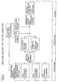
- the logic flow path is shown in Fig. 3.
- the system uses one or more opener assemblies or a plurality of assemblies on a drill to monitor and sample changes in general soil strength across the width of the drill, and adjusts the common pressure to all rams so that all openers can respond in like manner to the general change in soil strength.
- each individual opener monitors the changes in soil strength which it alone encounters and adjusts the pressure to its ram in isolation, so as to compensate for changes in soil strength in that soil zone alone while independent adjustments are being made by all other opener assemblies in the cluster of assemblies attached to the seed drill, to compensate for their particular changes of soil strength in their operating zones.
- the system is not restricted to the opener configuration shown in Fig 1.
- Any opener assembly which has a depth gauging device, the net loading on which could be monitored electronically, hydraulically, pneumatically or mechanically can be adapted to operate with either the simple form or the sensitive form of the system described.
- the invention utilizes the information provided from monitoring the net or overload forces experienced by the gauging devices in order to control the gross downforce in all or any of the openers on a seed drill so that a predetermined and consistent depth of operation in the soil is maintained together with a predetermined and consistent loading on the gauging devices regardless of changes in soil strength.
- the novel system also has built into the monitoring function, a means of predetermining the desirable loading in the gauge devices since different soils require different closure pressures. Having predetermined the desirable loading however, the system then maintains that value automatically.
- the sensors required to provide the information are designed around standard devices for measuring force or displacement.
- An example of the latter, monitored electronically is shown in Fig 2.
- the flow of logic required to utilize the information is shown in Fig 3.
- the flexibility in filtering the logic is somewhat more restrictive as shown in Fig 3 compared with electronic processing of the information.
- the connecting eyes at either end of the adjustment arrangement 10 are connected to the opener 2 (Fig 1) at 3, and to the gauge wheel assembly 8 (Fig 1) at 9.
- compressive loads on the device displace the moving core 1 (Fig 2) in a displacement transducer 2 (Fig 2), by deflecting the preloaded compression spring 3 (Fig 2).
- the sensing device preferably is either not compressible or is compressible only to a limited extent. In the example shown in Fig 2, a small amount of compressibility is tolerated in order to facilitate the use of an inexpensive displacement transducer. An alternative and more expensive option would be a load cell.
- the signal is relayed for processing within the electronic intelligence through the signal leads 4 (Fig 2).
- the electronic intelligence in turn controls the supply of oil to and from the downforce ram 16 (Fig 1).
- the length (depth) adjustment clamp 5 (Fig 2) is not related to the functioning of the sensor. It is the means of altering the basic depth of operation of the entire opener assembly.
- the assembly shown in Fig 2 periodically operates in tension while it supports the weight of the gauging assembly. No monitoring is required in this tension mode.
- a retention cap 6 (Fig 2) is sufficient for this function.
- Teflon or similar slip rings 8 serve to exclude dust while reducing hysteresis from friction to a minimum.
- An opener travelling in a given soil requires 100 kg of downforce to achieve 40 mm penetration depth.
- the gauge wheels (which also close the seed groove) require 20 kg to perform their closure function. They are positioned so that when they are in contact with the ground and loaded to 20 kg. the penetration (and thus seeding) depth is maintained at 40 mm.
- the gross downforce required is thus 120 kg.
- 120 kg downforce is provided by a given hydraulic ram of area 0.001 m2 operating at an oil pressure of 120,000 kg/m2.
- the opener encounters harder soil (of increased soil strength) which would require 150 kg of downforce to maintain 40 mm penetration depth.
- the additional 20 kg closure force required by the gauge wheels means the new total gross force required is now 170 kg.
- the opener would instead travel at a shallower depth in order to re-establish an equilibrium.
- the gauge wheels would ride clear of the ground.
- the gauge wheel sensing device will immediately signal the control valves to increase the oil pressure supply to the rams. This oil pressure will rise until it reaches 170,000 kg/m2 at which point it will provide 170 kg of downforce (which will then reinstate the 20 kg of net force on the gauge wheels). The new force thereby maintains seeding depth at 40 mm regardless of the change in soil strength. This is the primary function of the system.
- the sensitivity of the system will be adjustable so that change in soil strength can be detected at any predetermined interval.
- openers are required to rise and fall every few mm in order to follow ground contour without altering the air or hydraulic pressure.
- oil is supplied to or discharged from the rams at constant pressure in order to alter their displacement rather than their force. This can be achieved either by a cushioned constant oil pressure, or by the controls which our system provides.
- the soil strength sensitive system described above will preferably work together with a gas- or spring-cushioned supply of oil in each ram; or using air rams because air itself is compressible and would provide this cushion function automatically.
- the present invention therefore, relates to a system of using a gauge means or device to sense the magnitude of downforce less than or additional to that already required to establish equilibrium seeding depth to maintain that equilibrium i.e. using the signal to change the gross downforce so that a constant uplift force on the gauging device results, regardless of changes in soil strength and within the limits of the maximum fluid pressure available for creating gross downforce in the first place.
Landscapes
- Life Sciences & Earth Sciences (AREA)
- Soil Sciences (AREA)
- Environmental Sciences (AREA)
- Sowing (AREA)
- Earth Drilling (AREA)
- Pretreatment Of Seeds And Plants (AREA)
- Soil Working Implements (AREA)
Claims (11)
- Appareil capable d'avancer ayant une pluralité d'ensembles à ouvreuse, chacun ou au moins certains desdits ensembles à ouvreuse comprenant :
un membre de pénétration de la terre (4, 5, 13),
un membre de mesure (6) attaché sur pivot (11) au membre de pénétration de la terre, un moyen d'ajustement (10) pour modifier la profondeur de travail du membre de pénétration de la terre, et un moyen (16) pour un ajustement en force descendante sur le membre de pénétration de la terre ;
caractérisé en ce que :
des moyens capteurs (10) sont prévus pour capter une force d'élévation du membre de mesure depuis le sol, lesdits moyens capteurs étant couplés en opération au membre de mesure ;
le moyen d'ajustement (10) est attaché de manière pivotable (9) au membre de mesure et (3) au membre de pénétration de la terre ; et
le moyen pour un ajustement de force descendante sur le membre de pénétration de la terre est sensible à la force d'élévation captée sur le membre de mesure et ajuste la force descendante sur le membre de pénétration de la terre de manière à maintenir une profondeur de pénétration de la terre sensiblement constante du membre de pénétration de la terre et une charge en excès sensiblement constante sur le membre de mesure. - Appareil selon la revendication 1, caractérisé en ce que ledit appareil capable d'avancer est une machine capable d'avancer en étant remorquée ou poussée par un véhicule à moteur.
- Appareil selon l'une ou l'autre des revendications précédentes, dans laquel lesdits ensembles à ouvreuse sont portés comme un agencement fixe à partir d'un bâti capable d'être tiré ou poussé par un véhicule à moteur.
- Appareil selon la revendication 2 ou 3, caractérisé en ce que ledit appareil est un semoir en lignes.
- Appareil selon la revendication 4, caractérisé en ce que le semoir en lignes possède de multiples ensembles à ouvreuse comme définis à la revendication 1.
- Appareil selon une revendication précédente quelconque, caractérisé en ce que chaque dit membre de pénétration de la terre est une ouvreuse de semoir en lignes de pénétration de la terre.
- Appareil selon la revendication 6, caractérisé en ce que ladite ouvreuse de semoir pénètre la terre en conjonction avec un disque.
- Appareil selon les revendications dans une revendication précédente quelconque, caractérisé en ce que ledit membre de mesure est un support de charrue.
- Appareil selon la revendication 8, caractérisé en ce que ledit support de charrue agit en cours d'usage pour fermer une tranchée ouverte par ledit membre de pénétration de la terre.
- Appareil selon une revendication précédente quelconque, caractérisé en ce que la force descendante est appliquée pneumatiquement ou hydrauliquement contre le poids sur un bâti portant les ensembles à ouvreuse.
- Méthode de contrôle de la pénétration de la terre par les ensembles à ouvreuse d'un semoir en lignes, caractérisée par les étapes de :
capter une force d'élévation depuis la terre sur un membre de mesure qui passe au-dessus du sol à proximité du membre de pénétration de la terre de l'ensemble a ouvreuse ; et
prévoir un ajustement en force descendante sur ledit membre de pénétration de la terre en réponse à la force d'élévation captée sur le membre de mesure, pour maintenir une profondeur de pénétration sensiblement constante du membre de pénétration de la terre et une charge en excès sensiblement constante sur le membre de mesure.
Priority Applications (1)
| Application Number | Priority Date | Filing Date | Title |
|---|---|---|---|
| AT89312659T ATE101477T1 (de) | 1988-12-06 | 1989-12-05 | Regelsystem zum erzeugen der niederdrueckkraft fuer drillschare. |
Applications Claiming Priority (2)
| Application Number | Priority Date | Filing Date | Title |
|---|---|---|---|
| NZ227221 | 1988-12-06 | ||
| NZ227221A NZ227221A (en) | 1988-12-06 | 1988-12-06 | Maintaining seed drill opener at constant depth by constantly monitoring soil reaction force on gauge wheel |
Publications (3)
| Publication Number | Publication Date |
|---|---|
| EP0372901A2 EP0372901A2 (fr) | 1990-06-13 |
| EP0372901A3 EP0372901A3 (fr) | 1991-01-02 |
| EP0372901B1 true EP0372901B1 (fr) | 1994-02-16 |
Family
ID=19922683
Family Applications (1)
| Application Number | Title | Priority Date | Filing Date |
|---|---|---|---|
| EP89312659A Expired - Lifetime EP0372901B1 (fr) | 1988-12-06 | 1989-12-05 | Système d'automatisme pour atteindre la force à baisser pour des ouvreurs à dent |
Country Status (8)
| Country | Link |
|---|---|
| EP (1) | EP0372901B1 (fr) |
| AT (1) | ATE101477T1 (fr) |
| AU (1) | AU636587B2 (fr) |
| CA (1) | CA2004787C (fr) |
| DE (1) | DE68913165T2 (fr) |
| ES (1) | ES2050254T3 (fr) |
| NZ (1) | NZ227221A (fr) |
| ZA (1) | ZA899312B (fr) |
Cited By (6)
| Publication number | Priority date | Publication date | Assignee | Title |
|---|---|---|---|---|
| US8561472B2 (en) | 2007-01-08 | 2013-10-22 | Precision Planting Llc | Load sensing pin |
| US9144189B2 (en) | 2012-07-25 | 2015-09-29 | Precision Planting Llc | Integrated implement downforce control systems, methods, and apparatus |
| US9173339B2 (en) | 2007-09-26 | 2015-11-03 | Precision Planting Llc | System and method for determining proper downforce for a planter row unit |
| US9288937B2 (en) | 2011-08-05 | 2016-03-22 | Precision Planting Llc | Apparatus, systems and methods for row unit downforce control |
| US10309427B2 (en) | 2010-12-16 | 2019-06-04 | Precision Planting Llc | Variable pressure control system for dual acting actuators |
| US11439056B2 (en) | 2016-10-20 | 2022-09-13 | Precision Planting, Llc | Air seeder frame force control |
Families Citing this family (27)
| Publication number | Priority date | Publication date | Assignee | Title |
|---|---|---|---|---|
| DE4237093A1 (de) * | 1992-11-03 | 1994-05-05 | Amazonen Werke Dreyer H | Direktsämaschine für das Direktsaatverfahren |
| DE19534740C2 (de) * | 1995-09-19 | 1998-01-29 | Koeckerling Landmaschf Gmbh | Drillmaschine zum Ausbringen von Saatgut in vorbereitetem und nicht vorbereitetem Boden |
| RU2376743C2 (ru) * | 2007-08-27 | 2009-12-27 | Федеральное Государственное Образовательное Учреждение Высшего Профессионального Образования "Самарская государственная сельскохозяйственная академия" | Способ и устройство для внесения удобрения при культивировании |
| US7481278B1 (en) | 2007-11-14 | 2009-01-27 | Cnh America, Llc | System and method for a disc opener with gauge wheel depth adjustment assembly |
| DE102010006169B4 (de) * | 2010-01-29 | 2015-04-09 | Lemken Gmbh & Co. Kg | Doppelscheibenschar mit Tiefenführungsrolle |
| US9968030B2 (en) | 2010-06-22 | 2018-05-15 | Cnh Industrial Canada, Ltd. | Down pressure adjustment device and method for use with a disc opener assembly of an agricultural implement |
| US8634992B2 (en) | 2011-01-26 | 2014-01-21 | Precision Planting Llc | Dynamic supplemental downforce control system for planter row units |
| US8577561B2 (en) | 2011-03-08 | 2013-11-05 | Deere & Company | Control system and method of operating a product distribution machine |
| US8910582B2 (en) | 2011-04-11 | 2014-12-16 | Deere & Company | Row unit for a seeding machine having active downforce control for the closing wheels |
| EP2713690B1 (fr) | 2011-06-03 | 2017-08-09 | Precision Planting LLC | Appareil, systèmes et procédés pour barre porte-outils agricole |
| US8380356B1 (en) | 2012-06-12 | 2013-02-19 | Ag Leader Technology | Seeder downforce section control |
| US9706703B2 (en) | 2014-12-11 | 2017-07-18 | Cnh Industrial America Llc | Independent closing system with adjustable down force |
| US9826677B2 (en) | 2014-12-16 | 2017-11-28 | Cnh Industrial Canada, Ltd. | Seed implement incorporating a down pressure sensing and adjustment system |
| CN105123002B (zh) * | 2015-07-26 | 2017-12-29 | 葛伟岸 | 后置式开沟机机架 |
| US11277961B2 (en) | 2018-02-09 | 2022-03-22 | Ag Leader Technology | Seed spacing device for an agricultural planter and related systems and methods |
| WO2019164919A1 (fr) | 2018-02-20 | 2019-08-29 | Ag Leader Technology | Appareil, systèmes et procédés d'application de fluide |
| US20190297769A1 (en) | 2018-03-30 | 2019-10-03 | Ag Leader Technology | Devices, Systems, and Methods for Seed Trench Protection |
| US12520744B2 (en) | 2018-11-15 | 2026-01-13 | Ag Leader Technology | On the go organic matter sensor and associated systems and methods |
| DE202019100914U1 (de) * | 2019-02-19 | 2020-05-20 | Pöttinger Landtechnik Gmbh | Säscharanordnung mit druckregelbarer Druckrolle |
| US11006567B2 (en) | 2019-04-18 | 2021-05-18 | Cnh Industrial America Llc | System and method for controlling the operation of a seed-planting implement based on the operation of its furrow-closing assembly |
| US11224159B2 (en) | 2019-06-28 | 2022-01-18 | Cnh Industrial Canada, Ltd. | Downforce monitoring system for an agricultural row unit |
| US11566997B2 (en) | 2020-01-14 | 2023-01-31 | Cnh Industrial Canada, Ltd. | System and method for monitoring soil composition at different depths within a field |
| US12268115B2 (en) | 2020-02-07 | 2025-04-08 | Ag Leader Technology | Planter obstruction monitoring and associated devices and methods |
| US12477973B2 (en) | 2020-11-13 | 2025-11-25 | Ag Leader Technology | Agricultural high speed row unit |
| CN115211264B (zh) * | 2022-07-08 | 2024-07-02 | 内蒙古自治区农牧业科学院 | 一种打孔式草地免耕播种装置 |
| CN116897723A (zh) * | 2022-08-01 | 2023-10-20 | 中国农业科学院都市农业研究所 | 一种基于植物感光基因调节的光源排列系统及方法 |
| DE102023130921A1 (de) | 2023-11-08 | 2025-05-08 | Horsch Maschinen Gmbh | Landwirtschaftliche arbeitsmaschine und verfahren zum betrieb einer landwirtschaftlichen arbeitsmaschine |
Family Cites Families (4)
| Publication number | Priority date | Publication date | Assignee | Title |
|---|---|---|---|---|
| DD213579A1 (de) * | 1983-02-10 | 1984-09-19 | Landmaschinenbau Bernburg Veb | Vorrichtung zum regeln der arbeitstiefe der saeschare |
| DE3321816C2 (de) * | 1983-06-16 | 1986-09-25 | Amazonen-Werke H. Dreyer Gmbh & Co Kg, 4507 Hasbergen | Drillmaschine |
| DE3527760A1 (de) * | 1985-08-02 | 1987-02-12 | Amazonen Werke Dreyer H | Saemaschine |
| US4671193A (en) * | 1985-12-27 | 1987-06-09 | States Alan E | Planting tool |
-
1988
- 1988-12-06 NZ NZ227221A patent/NZ227221A/xx unknown
-
1989
- 1989-12-05 DE DE68913165T patent/DE68913165T2/de not_active Expired - Fee Related
- 1989-12-05 AT AT89312659T patent/ATE101477T1/de active
- 1989-12-05 EP EP89312659A patent/EP0372901B1/fr not_active Expired - Lifetime
- 1989-12-05 ES ES89312659T patent/ES2050254T3/es not_active Expired - Lifetime
- 1989-12-06 AU AU45993/89A patent/AU636587B2/en not_active Ceased
- 1989-12-06 CA CA002004787A patent/CA2004787C/fr not_active Expired - Fee Related
- 1989-12-06 ZA ZA899312A patent/ZA899312B/xx unknown
Cited By (9)
| Publication number | Priority date | Publication date | Assignee | Title |
|---|---|---|---|---|
| US8561472B2 (en) | 2007-01-08 | 2013-10-22 | Precision Planting Llc | Load sensing pin |
| US10548254B2 (en) | 2007-01-08 | 2020-02-04 | Precision Planting Llc | Load sensing pin for an agricultural implement |
| US9173339B2 (en) | 2007-09-26 | 2015-11-03 | Precision Planting Llc | System and method for determining proper downforce for a planter row unit |
| US10309427B2 (en) | 2010-12-16 | 2019-06-04 | Precision Planting Llc | Variable pressure control system for dual acting actuators |
| US9288937B2 (en) | 2011-08-05 | 2016-03-22 | Precision Planting Llc | Apparatus, systems and methods for row unit downforce control |
| US9144189B2 (en) | 2012-07-25 | 2015-09-29 | Precision Planting Llc | Integrated implement downforce control systems, methods, and apparatus |
| US9879702B2 (en) | 2012-07-25 | 2018-01-30 | Precision Planting Llc | Integrated implement downforce control systems, methods, and apparatus |
| US10443631B2 (en) | 2012-07-25 | 2019-10-15 | Precision Planting Llc | Integrated implement downforce control systems, methods, and apparatus |
| US11439056B2 (en) | 2016-10-20 | 2022-09-13 | Precision Planting, Llc | Air seeder frame force control |
Also Published As
| Publication number | Publication date |
|---|---|
| ATE101477T1 (de) | 1994-03-15 |
| CA2004787C (fr) | 1995-05-23 |
| NZ227221A (en) | 1992-11-25 |
| ZA899312B (en) | 1990-09-26 |
| EP0372901A3 (fr) | 1991-01-02 |
| ES2050254T3 (es) | 1994-05-16 |
| AU636587B2 (en) | 1993-05-06 |
| DE68913165D1 (de) | 1994-03-24 |
| CA2004787A1 (fr) | 1990-06-06 |
| AU4599389A (en) | 1990-06-14 |
| DE68913165T2 (de) | 1994-08-25 |
| EP0372901A2 (fr) | 1990-06-13 |
Similar Documents
| Publication | Publication Date | Title |
|---|---|---|
| EP0372901A2 (fr) | Système d'automatisme pour atteindre la force à baisser pour des ouvreurs à dent | |
| US6389999B1 (en) | Dynamic controller of excess downpressure for surface engaging implement | |
| US11617295B2 (en) | Dynamic supplemental downforce control system for planter row units | |
| US11064651B2 (en) | Down pressure adjustment device and method for use with a disc opener assembly of an agricultural implement | |
| US5479992A (en) | Agricultural implement controller to compensate for soil hardness variation | |
| US9848522B2 (en) | Agricultural system | |
| US9026321B2 (en) | System and method for controlling soil finish from an agricultural implement | |
| US7975630B2 (en) | Method for adjusting and controlling packing force | |
| US10582653B2 (en) | Agricultural planting system with automatic depth control | |
| US11197411B2 (en) | Agricultural planting system with automatic depth control | |
| US6701857B1 (en) | Depth control device for planting implement | |
| US10517204B2 (en) | Implement weight management systems, methods, and apparatus | |
| US10444774B2 (en) | Agricultural system | |
| US20120125244A1 (en) | Mapping soil hardness | |
| US4759301A (en) | Seed drill | |
| EP4179857A1 (fr) | Unité de rangée | |
| CA2784210C (fr) | Systeme de commande d'outils pour semoirs agricoles | |
| EP4366502B1 (fr) | Procédé d'étalonnage d'un outil agricole, et outil agricole | |
| EP3714671B1 (fr) | Système de plantation agricole comportant un dispositif automatique de commande de profondeur |
Legal Events
| Date | Code | Title | Description |
|---|---|---|---|
| PUAI | Public reference made under article 153(3) epc to a published international application that has entered the european phase |
Free format text: ORIGINAL CODE: 0009012 |
|
| AK | Designated contracting states |
Kind code of ref document: A2 Designated state(s): AT BE CH DE ES FR GB GR IT LI LU NL SE |
|
| PUAL | Search report despatched |
Free format text: ORIGINAL CODE: 0009013 |
|
| AK | Designated contracting states |
Kind code of ref document: A3 Designated state(s): AT BE CH DE ES FR GB GR IT LI LU NL SE |
|
| 17P | Request for examination filed |
Effective date: 19910702 |
|
| 17Q | First examination report despatched |
Effective date: 19920514 |
|
| GRAA | (expected) grant |
Free format text: ORIGINAL CODE: 0009210 |
|
| AK | Designated contracting states |
Kind code of ref document: B1 Designated state(s): AT BE CH DE ES FR GB GR IT LI LU NL SE |
|
| PG25 | Lapsed in a contracting state [announced via postgrant information from national office to epo] |
Ref country code: IT Free format text: LAPSE BECAUSE OF FAILURE TO SUBMIT A TRANSLATION OF THE DESCRIPTION OR TO PAY THE FEE WITHIN THE PRE;WARNING: LAPSES OF ITALIAN PATENTS WITH EFFECTIVE DATE BEFORE 2007 MAY HAVE OCCURRED AT ANY TIME BEFORE 2007. THE CORRECT EFFECTIVE DATE MAY BE DIFFERENT FROM THE ONE RECORDED.SCRIBED TIME-LIMIT Effective date: 19940216 Ref country code: AT Effective date: 19940216 Ref country code: CH Effective date: 19940216 Ref country code: BE Effective date: 19940216 Ref country code: SE Effective date: 19940216 Ref country code: GR Free format text: LAPSE BECAUSE OF FAILURE TO SUBMIT A TRANSLATION OF THE DESCRIPTION OR TO PAY THE FEE WITHIN THE PRESCRIBED TIME-LIMIT Effective date: 19940216 Ref country code: NL Effective date: 19940216 Ref country code: LI Effective date: 19940216 |
|
| REF | Corresponds to: |
Ref document number: 101477 Country of ref document: AT Date of ref document: 19940315 Kind code of ref document: T |
|
| REF | Corresponds to: |
Ref document number: 68913165 Country of ref document: DE Date of ref document: 19940324 |
|
| REG | Reference to a national code |
Ref country code: ES Ref legal event code: FG2A Ref document number: 2050254 Country of ref document: ES Kind code of ref document: T3 |
|
| REG | Reference to a national code |
Ref country code: CH Ref legal event code: PL |
|
| ET | Fr: translation filed | ||
| NLV1 | Nl: lapsed or annulled due to failure to fulfill the requirements of art. 29p and 29m of the patents act | ||
| PLBE | No opposition filed within time limit |
Free format text: ORIGINAL CODE: 0009261 |
|
| STAA | Information on the status of an ep patent application or granted ep patent |
Free format text: STATUS: NO OPPOSITION FILED WITHIN TIME LIMIT |
|
| PG25 | Lapsed in a contracting state [announced via postgrant information from national office to epo] |
Ref country code: LU Free format text: LAPSE BECAUSE OF NON-PAYMENT OF DUE FEES Effective date: 19941231 |
|
| 26N | No opposition filed | ||
| PGFP | Annual fee paid to national office [announced via postgrant information from national office to epo] |
Ref country code: GB Payment date: 19960122 Year of fee payment: 7 |
|
| PGFP | Annual fee paid to national office [announced via postgrant information from national office to epo] |
Ref country code: FR Payment date: 19960125 Year of fee payment: 7 |
|
| PGFP | Annual fee paid to national office [announced via postgrant information from national office to epo] |
Ref country code: DE Payment date: 19960126 Year of fee payment: 7 |
|
| PGFP | Annual fee paid to national office [announced via postgrant information from national office to epo] |
Ref country code: ES Payment date: 19960131 Year of fee payment: 7 |
|
| PG25 | Lapsed in a contracting state [announced via postgrant information from national office to epo] |
Ref country code: GB Effective date: 19961205 |
|
| GBPC | Gb: european patent ceased through non-payment of renewal fee |
Effective date: 19961205 |
|
| PG25 | Lapsed in a contracting state [announced via postgrant information from national office to epo] |
Ref country code: FR Effective date: 19970829 |
|
| PG25 | Lapsed in a contracting state [announced via postgrant information from national office to epo] |
Ref country code: DE Effective date: 19970902 |
|
| REG | Reference to a national code |
Ref country code: FR Ref legal event code: ST |
|
| PG25 | Lapsed in a contracting state [announced via postgrant information from national office to epo] |
Ref country code: ES Free format text: LAPSE BECAUSE OF NON-PAYMENT OF DUE FEES Effective date: 19971206 |
|
| REG | Reference to a national code |
Ref country code: GB Ref legal event code: 728V |
|
| REG | Reference to a national code |
Ref country code: GB Ref legal event code: 728V |
|
| REG | Reference to a national code |
Ref country code: GB Ref legal event code: 7281 |
|
| REG | Reference to a national code |
Ref country code: ES Ref legal event code: FD2A Effective date: 19980113 |