EP0372913A1 - Compresseur à plateau en biais - Google Patents
Compresseur à plateau en biais Download PDFInfo
- Publication number
- EP0372913A1 EP0372913A1 EP89312684A EP89312684A EP0372913A1 EP 0372913 A1 EP0372913 A1 EP 0372913A1 EP 89312684 A EP89312684 A EP 89312684A EP 89312684 A EP89312684 A EP 89312684A EP 0372913 A1 EP0372913 A1 EP 0372913A1
- Authority
- EP
- European Patent Office
- Prior art keywords
- balance weight
- plate
- wobble plate
- annular
- drive shaft
- Prior art date
- Legal status (The legal status is an assumption and is not a legal conclusion. Google has not performed a legal analysis and makes no representation as to the accuracy of the status listed.)
- Granted
Links
- 230000033001 locomotion Effects 0.000 claims abstract description 16
- 239000003507 refrigerant Substances 0.000 claims description 20
- 230000007246 mechanism Effects 0.000 claims description 12
- 230000008878 coupling Effects 0.000 claims description 7
- 238000010168 coupling process Methods 0.000 claims description 7
- 238000005859 coupling reaction Methods 0.000 claims description 7
- 238000005461 lubrication Methods 0.000 abstract 1
- 239000010687 lubricating oil Substances 0.000 description 6
- 230000002093 peripheral effect Effects 0.000 description 6
- 230000008859 change Effects 0.000 description 3
- 238000004891 communication Methods 0.000 description 3
- 238000001816 cooling Methods 0.000 description 3
- 239000003921 oil Substances 0.000 description 3
- XEEYBQQBJWHFJM-UHFFFAOYSA-N Iron Chemical compound [Fe] XEEYBQQBJWHFJM-UHFFFAOYSA-N 0.000 description 2
- 230000007423 decrease Effects 0.000 description 2
- 230000004044 response Effects 0.000 description 2
- 230000000717 retained effect Effects 0.000 description 2
- 208000021019 wobble Diseases 0.000 description 2
- 241001052209 Cylinder Species 0.000 description 1
- 235000014676 Phragmites communis Nutrition 0.000 description 1
- 238000004378 air conditioning Methods 0.000 description 1
- 230000015572 biosynthetic process Effects 0.000 description 1
- 238000010276 construction Methods 0.000 description 1
- 230000000875 corresponding effect Effects 0.000 description 1
- 230000003247 decreasing effect Effects 0.000 description 1
- 230000007547 defect Effects 0.000 description 1
- 230000001419 dependent effect Effects 0.000 description 1
- 238000006073 displacement reaction Methods 0.000 description 1
- 229910052742 iron Inorganic materials 0.000 description 1
- OYIKARCXOQLFHF-UHFFFAOYSA-N isoxaflutole Chemical compound CS(=O)(=O)C1=CC(C(F)(F)F)=CC=C1C(=O)C1=C(C2CC2)ON=C1 OYIKARCXOQLFHF-UHFFFAOYSA-N 0.000 description 1
- 230000013011 mating Effects 0.000 description 1
- 239000002184 metal Substances 0.000 description 1
- 229910052751 metal Inorganic materials 0.000 description 1
- 238000000034 method Methods 0.000 description 1
- 239000000203 mixture Substances 0.000 description 1
- 230000008569 process Effects 0.000 description 1
- 238000000926 separation method Methods 0.000 description 1
Images


Classifications
-
- F—MECHANICAL ENGINEERING; LIGHTING; HEATING; WEAPONS; BLASTING
- F04—POSITIVE - DISPLACEMENT MACHINES FOR LIQUIDS; PUMPS FOR LIQUIDS OR ELASTIC FLUIDS
- F04B—POSITIVE-DISPLACEMENT MACHINES FOR LIQUIDS; PUMPS
- F04B25/00—Multi-stage pumps
- F04B25/04—Multi-stage pumps having cylinders coaxial with, or parallel or inclined to, main shaft axis
-
- F—MECHANICAL ENGINEERING; LIGHTING; HEATING; WEAPONS; BLASTING
- F04—POSITIVE - DISPLACEMENT MACHINES FOR LIQUIDS; PUMPS FOR LIQUIDS OR ELASTIC FLUIDS
- F04B—POSITIVE-DISPLACEMENT MACHINES FOR LIQUIDS; PUMPS
- F04B27/00—Multi-cylinder pumps specially adapted for elastic fluids and characterised by number or arrangement of cylinders
- F04B27/08—Multi-cylinder pumps specially adapted for elastic fluids and characterised by number or arrangement of cylinders having cylinders coaxial with, or parallel or inclined to, main shaft axis
- F04B27/0873—Component parts, e.g. sealings; Manufacturing or assembly thereof
- F04B27/0878—Pistons
- F04B27/0882—Pistons piston shoe retaining means
Definitions
- the present invention relates to a refrigerant compressor, and more particularly, to a wobble plate type refrigerant compressor for use in an automotive air conditioning system.
- a slant plate type compressor such as a wobble plate type compressor, includes a balance weight ring of substantial mass disposed on the nose of the hub or "boss" of the slant plate, in order to balance the slant plate under dynamic operation conditions.
- the balance weight ring is held in place by means of a retaining ring.
- FIG. 5 shows a slant plate type compressor as disclosed in the Japanese application.
- Wobble plate 60 is mounted about boss 54 of slant plate 50 through bearings 61 and 62 so that slant plate 50 is rotatable with respect thereto.
- Boss 54 includes smaller diameter portion 54a at an axially rearward end (to the right in Figure 5) thereof, resulting in the formation of annular shoulder 541 forward of portion 54a.
- Wobble plate 60 includes annular projection 601 formed at an inner periphery of the axially rearward surface thereof and terminated so as to be same axial level of annular shoulder 541.
- Annular balance weight ring 500 is mounted about smaller diameter portion 54a in contact with shoulder 541 and annular projection 601.
- Balance weight ring 500 includes annular depression 501 formed at an inner periphery of the axially rearward surface, reducing the thickness of ring 500 at the inner periphery. Relatively thin plate portion 502 remains at the inner periphery of balance weight ring 500, forward of depression 501.
- Annular groove 55 is formed in the radially outer peripheral surface of smaller diameter portion 54a, and annular snap ring 56 is disposed therein. The radially outer portion of snap ring 56 extends exteriorly of groove 55 and contacts thin plate portion 502 of balance weight ring 500. Thin plate portion 502 of balance weight ring 500 is retained between snap ring 56 and annular shoulder 541.
- balance weight ring 500 is affixed to boss 54 and prevents the axial movement of wobble plate 60. Consequently, an axially rearward end surface of annular projection 601 always contacts the axially forward surface of balance weight ring 500 during operation of the compressor causing friction between annular projection 601 and balance weight ring 500. Excessive rotational friction can occur between annular projection 601 and balance weight ring 500 during compressor operation causing considerable defects such as unusual wear or seizure between annular projection 601 and balance weight ring 500.
- a wobble plate type refrigerant compressor including an annular balance weight ring which can balance a slant plate and prevent the axial movement of a wobble plate under dynamic operating conditions while smoothly rotating on a wobble plate in a bearingless structure.
- a wobble plate type compressor in accordance with the present invention includes a compressor housing having a cylinder block.
- the cylinder block includes a plurality of peripherally disposed cylinders.
- a crank chamber is enclosed within the cylinder block, forward of the location of the cylinders.
- the compressor housing includes a suction chamber and a discharge chamber formed therein.
- a piston is slidably fitted within each of the cylinders, and a drive mechanism is coupled to the pistons to reciprocate the pistons within the cylinders.
- the drive mechanism includes a drive shaft rotatably supported in the housing, and a coupling mechanism including a slant plate mounted about the drive shaft.
- the coupling mechanism converts rotational motion of the drive shaft into reciprocating motion of the pistons in the cylinders.
- the slant plate is disposed at an angle to the drive shaft.
- Tlie compressor further includes an annular balance weight having a centrally located thin plate region defining a recessed portion.
- the coupling mechanism further includes a wobble plate disposed about the boss of the slant plate. The annular balance weight is retained on the boss of the slant plate to balance the slant plate and to prevent axial movement of the wobble plate under dynamic operating conditions.
- the pistons are linked to the wobble plate by connecting rods. The rotational motion of the drive shaft and the slant plate causes the wobble plate to nutate and reciprocate the pistons in the cylinders.
- the annular balance weight includes a plurality of holes formed at the thin plate region so as to face an end surface of the wobble plate and a tapered annular side wall of the recessed portion in order to efficiently conduct lubricating oil to the friction surface between the wobble plate and the annular balance weight.
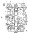
- Compressor 10 includes cylindrical housing assembly 20 including cylinder block 21, front end plate 23 disposed at one end of cylinder block 21, crank chamber 22 formed within cylinder block 21, and rear end plate 24 disposed at the opposite end of cylinder block 21.
- Front end plate 23 is mounted on the open forward end of cylinder block 21 by a plurality of bolts 101 to enclose crank chamber 22 therein.
- Rear end plate 24 is mounted on cylinder block 21 at its opposite end by a plurality of bolts 102.
- Valve plate 25 is located between rear end plate 24 and cylinder block 21. Opening 231 is centrally formed in front end plate 23.
- Drive shaft 26 is supported by bearing 30 disposed in opening 231.
- Central bore 210 extends through cylinder block 21 to a rearward end surface.
- the inner (rear) end portion of drive shaft 26 is rotatably supported by bearing 31 disposed within central bore 210 of cylinder block 21.
- Valve control mechanism 19 is disposed in bore 210 to the rear of drive shaft 26.
- Cam rotor 40 is fixed on drive shaft 26 by pin member 261, and rotates with shaft 26.
- Thrust needle bearing 32 is disposed between the axial inner (rear) end surface of front end plate 23 and the adjacent forward axial end surface of cam rotor 40.
- Cam rotor 40 includes arm 41 having pin member 42 extending therefrom.
- Slant plate 50 is disposed about drive shaft 26 and includes opening 53 through which drive shaft 26 passes.
- Slant plate 50 is disposed adjacent cam rotor 40.
- Slant plate 50 includes arm 51 having slot 52 and boss 54.
- Cam rotor 40 and slant plate 50 are connected by pin member 42, which is inserted in slot 52 to create a hinged joint. Pin member 42 is slidable within slot 52 to allow adjustment of the angular position of slant plate 50 with respect to the longitudinal axis of drive shaft 26.
- Wobble plate 60 is mounted about boss 54 of slant plate 50 through bearings 61 and 62 so that slant plate 50 is rotatable with respect thereto. Rotational motion of slant plate 50 causes nutational motion of wobble plate 60.
- Fork shaped slider 63 is attached to the outer peripheral end of wobble plate 60 and is slidably mounted on sliding rail 64 held between front end plate 23 and cylinder block 21. Fork shaped slider 63 prevents rotation of wobble plate 60 and wobble plate 60 reciprocates along rail 64 when cam rotor 40 and slant plate 50 rotate.
- Cylinder block 21 includes a plurality of peripherally located cylinder chambers 70 in which pistons 71 reciprocate. Each pistons 71 is connected to wobble plate 60 at a peripheral location by a corresponding connecting rod 72. Nutational motion of wobble plate 60 causes pistons 71 to reciprocate in cylinders 70 to compress refrigerant therein.
- Rear end plate 24 includes peripherally located annular suction chamber 241 and centrally located discharge chamber 251.
- Valve plate 25 is located between cylinder block 21 and rear end plate 24 and includes a plurality of valved suction ports 242 linking suction chamber 241 with respective cylinders 70.
- Valve plate 25 also includes a plurality of valved discharge ports 252 linking discharge chamber 251 with respective cylinders 70.
- Suction ports 242 and discharge ports 252 are provided with suitable reed valves as described in U.S. Patent No. 4,011,029 to Shimizu.
- Suction chamber 241 includes inlet portion 241a which is connected to an evaporator of the external cooling circuit (not shown).
- Discharge chamber 251 is provided with outlet portion 251a connected to a condenser of the cooling circuit (not shown).
- Gaskets 27 and 28 are located between cylinder block 21 and the inner surface of valve plate 25, and the outer surface of valve plate 25 and rear end plate 24, respectively, to seal the mating surfaces of cylinder block 21, valve plate 25 and rear end plate 24.
- Communication path 400 links crank chamber 22 and suction chamber 241 and includes central bore 210 and passageway 150.
- Valve control mechanism 19 controls the opening and closing of communication path 400 in order to vary the capacity of the compressor, as disclosed in Japanese Patent Application Publication No. 01-142,276.
- drive shaft 26 is rotated by the engine of the vehicle through electromagnetic clutch 300.
- Cam rotor 40 is rotated with drive shaft 26, rotating slant plate 50 as well, causing wobble plate 60 to nutate.
- Nutational motion of wobble plate 60 reciprocates pistons 71 in their respective cylinders 70.
- refrigerant gas which is introduced into suction chamber 241 through inlet portion 241a, flows into each cylinder 70 through suction ports 242 and is compressed therein.
- the compressed refrigerant gas is discharged into discharge chamber 251 from each cylinder 70 through discharge ports 252, and therefrom into the cooling circuit through outlet portion 251a.
- the capacity of compressor 10 may be adjusted to maintain a constant pressure in suction chamber 241 in response to a change in the heat load of the evaporator, or a change in the rotating speed of the compressor.
- the capacity of the compressor is adjusted by changing the angle of slant plate 50 with respect to a plane perpendicular to the axis of drive shaft 26. This angle is dependent upon the crank chamber pressure.
- An increase in crank chamber pressure decreases the slant angle of slant plate 50 and wobble plate 60, decreasing the capacity of the compressor.
- a decrease in the crank chamber pressure increases the angle of slant plate 50 and wobble plate 60 and thus increases the capacity of the compressor.
- valve control mechanism 19 acts in response to the crank chamber pressure, such that the acting point is modified according to the discharge chamber pressure, to control the link between the crank and suction chambers, to adjust the crank chamber pressure and thereby change the slant angle of slant plate 50 and vary the operating capacity of the compressor.
- valve control mechanism 19 acts in response to the crank chamber pressure, such that the acting point is modified according to the discharge chamber pressure, to control the link between the crank and suction chambers, to adjust the crank chamber pressure and thereby change the slant angle of slant plate 50 and vary the operating capacity of the compressor.
- valve control mechanism 19 acts in response to the crank chamber pressure, such that the acting point is modified according to the discharge chamber pressure, to control the link between the crank and suction chambers, to adjust the crank chamber pressure and thereby change the slant angle of slant plate 50 and vary the operating capacity of the compressor.
- other types of valve control mechanisms or none at all may be used according to the present invention.
- Compressor 10 further includes annular groove 55 formed in the radially outer surface of smaller diameter portion 54a of boss 54.
- Boss 54 includes annular shoulder 541 forward of smaller diameter portion 54a.
- Balance weight ring 500 includes annular depression 501 formed at a rearward, radially inner peripheral region, resulting in the thin plate portion 502 formed axially forward of depression 501.
- Thin plate portion 502 fits on annular shoulder 541 of boss 54.
- Annular member 80 made of soft metal, for example, untempered iron, disposed on thin plate portion 502 is caulked into groove 55 so as to retain balance weight ring 500 on boss 54 of slant plate 50 by sandwiching thin plate portion 502 against annular shoulder 541.
- Annular projection 601 is formed at an inner periphery of the axially rearward surface of wobble plate 60 and terminated to the radially outermost of the axially forward surface of thin plate portion 502. Consequently, an axially rearward end surface of annular projection 601 always contacts the radially outermost of the axially forward surface of thin plate portion 502 during operation of the compressor. Thereby, while axial movement of wobble plate 60 is prevented during compressor operation, rotational friction is created between annular projection 601 of wobble plate 60 and thin plate portion 502 of balance weight ring 500.
- balance weight ring 500 includes annular depression 501 of which annular side wall 501a is radially inwardly slanted.
- Thin plate portion 502 is provided with a plurality of axial holes 503 aligned with the periphery of the forward end of side wall 501a with an equiangular interval so as to face the rearward end surface of annular projection 601 of wobble plate 60.
- the refrigerant mixed with the mists of lubricating oil (hereinafter, this mixture is represented by "the refrigerant" for explanation only) is introduced into cylinders 70 from suction chamber 241 by the forward motion of pistons 71 and is compressed by the rearward motion of pistons 71.
- the refrigerant is blown into crank chamber 22 from cylinders 70 through the gap between an outer peripheral surface of pistons 71 and an inner peripheral surface of cylinders 70.
- a part of the refrigerant in crank chamber 22 flows back to suction chamber 241 through communication path 400.
- the separated oil sticking to the bottom surface of annular depression 501 of balance weight ring 500 moves radially outward and is gathered at the forward end of side wall 501a of annular depression 501.
- the separated oil sticking to annular side wall 501a moves forward along a slanted surface of side wall 501a due to the centrifugal force and gathers at the forward end of side wall 501a.
- the lubricating oil gathered at the forward end of side wall 501a flows into the friction surface between the rearward end surface of annular projection 601 of wobble plate 60 and the forward surface of thin plate portion 502 of balance weight ring 500 through axial holes 503. Accordingly, unusual wear or seizure between annular projection 601 and thin plate portion 502 is prevented without disposing a bearing between the axially rearward end surface of annular projection 601 and the axially forward surface of balance weight ring 500, even under extreme conditions.
- balance weight ring 500 Since balance weight ring 500 is located near central bore 210, the refrigerant adjacent to balance weight ring 500 is always replaced with the fresh refrigerant which is returning to suction chamber 241 from crank chamber 22 through communicating path 400. Therefore, lubricating oil is sufficiently supplied to the friction surface between the rearward end surface of annular projection 601 of wobble plate 60 and the forward surface of thin plate portion 502 of balance weight ring 500.
- FIG. 4 shows a second embodiment of the present invention.
- thin plate portion 502 of balance weight ring 500 is provided with a plurality of inclined holes 503′ aligned with the periphery of the forward end of side wall 501a at an equiangular interval.
- the inclined angle of holes 503′ corresponds to the slant angle of annular side wall 501a, that is, the line extending forward from the forward end of side wall 501a corresponds to the radially outermost line of holes 503′.
- the lubricating oil gathered at the forward end of side wall 501a is effectively conducted into the friction surface between the rearward end surface of annular projection 601 of wobble plate 60 and the forward surface of thin plate portion 502 of balance weight ring 500 through inclined holes 503′ due to centrifugal force.
Landscapes
- Engineering & Computer Science (AREA)
- Mechanical Engineering (AREA)
- General Engineering & Computer Science (AREA)
- Manufacturing & Machinery (AREA)
- Compressors, Vaccum Pumps And Other Relevant Systems (AREA)
- Compressor (AREA)
Applications Claiming Priority (2)
| Application Number | Priority Date | Filing Date | Title |
|---|---|---|---|
| JP1988159478U JPH0338461Y2 (fr) | 1988-12-09 | 1988-12-09 | |
| JP159478/88 | 1988-12-09 |
Publications (2)
| Publication Number | Publication Date |
|---|---|
| EP0372913A1 true EP0372913A1 (fr) | 1990-06-13 |
| EP0372913B1 EP0372913B1 (fr) | 1993-01-07 |
Family
ID=15694651
Family Applications (1)
| Application Number | Title | Priority Date | Filing Date |
|---|---|---|---|
| EP89312684A Expired - Lifetime EP0372913B1 (fr) | 1988-12-09 | 1989-12-06 | Compresseur à plateau en biais |
Country Status (9)
| Country | Link |
|---|---|
| US (1) | US4979877A (fr) |
| EP (1) | EP0372913B1 (fr) |
| JP (1) | JPH0338461Y2 (fr) |
| KR (1) | KR970004806B1 (fr) |
| CN (1) | CN1016208B (fr) |
| AU (1) | AU616327B2 (fr) |
| CA (1) | CA2005011C (fr) |
| DE (1) | DE68904301T2 (fr) |
| SG (1) | SG63993G (fr) |
Cited By (2)
| Publication number | Priority date | Publication date | Assignee | Title |
|---|---|---|---|---|
| EP0856662A3 (fr) * | 1997-01-31 | 1999-12-08 | Zexel Corporation | Compresseur à plateau en biais à capacité variable |
| EP0848162A3 (fr) * | 1996-12-13 | 1999-12-08 | Zexel Corporation | Compresseur à plateau en biais à capacité variable |
Families Citing this family (19)
| Publication number | Priority date | Publication date | Assignee | Title |
|---|---|---|---|---|
| JP2943935B2 (ja) * | 1990-04-10 | 1999-08-30 | サンデン株式会社 | 容量可変型斜板式圧縮機 |
| US5094590A (en) * | 1990-10-09 | 1992-03-10 | General Motors Corporation | Variable displacement compressor with shaft end play compensation |
| JP3026518B2 (ja) * | 1991-07-03 | 2000-03-27 | サンデン株式会社 | 容量可変型揺動板式圧縮機 |
| US5440878A (en) * | 1992-08-27 | 1995-08-15 | Vernon E. Gleasman | Variable hydraulic machine |
| JPH0968162A (ja) * | 1995-06-20 | 1997-03-11 | Toyota Autom Loom Works Ltd | 容量可変型斜板式圧縮機 |
| US5743090A (en) * | 1995-09-29 | 1998-04-28 | Barrowman; Andrew W. | Hydraulic torque transmitter and synchronizer |
| US6112639A (en) * | 1995-12-18 | 2000-09-05 | Kabushiki Kaisha Toyoda Jidoshokki Seisakusho | Structure for collecting leaking oil in compressor |
| JPH10196525A (ja) * | 1997-01-09 | 1998-07-31 | Sanden Corp | 斜板式圧縮機 |
| JPH10266953A (ja) * | 1997-03-25 | 1998-10-06 | Zexel Corp | 斜板式圧縮機 |
| JPH1193833A (ja) * | 1997-09-17 | 1999-04-06 | Toyota Autom Loom Works Ltd | 可変容量型斜板式圧縮機 |
| JPH11193781A (ja) * | 1997-12-26 | 1999-07-21 | Toyota Autom Loom Works Ltd | 可変容量型圧縮機 |
| EP1026397A3 (fr) * | 1999-02-01 | 2001-02-07 | Kabushiki Kaisha Toyoda Jidoshokki Seisakusho | Soupape de contrôle pour compresseur à capacité variable |
| JP2001140755A (ja) | 1999-11-17 | 2001-05-22 | Sanden Corp | 斜板式圧縮機 |
| US6823768B2 (en) | 2001-11-22 | 2004-11-30 | Sanden Corporation | Nitrided surface layer on a swash plate boss |
| JP2003269329A (ja) * | 2002-03-15 | 2003-09-25 | Sanden Corp | 自動車用コンプレッサ |
| CN100359164C (zh) * | 2003-10-29 | 2008-01-02 | 上海三电贝洱汽车空调有限公司 | 旋转斜盘式压缩机的旋转斜盘 |
| CN102997524A (zh) * | 2011-09-16 | 2013-03-27 | 万事康股份有限公司 | 制冷剂回收机 |
| FR2998023B1 (fr) * | 2012-11-12 | 2015-09-04 | Skf Ab | Dispositif de poulie, machine tournante equipee d'un tel dispositif et procede de montage d'un tel dispositif sur une machine tournante |
| CN110748468B (zh) * | 2019-11-28 | 2020-07-03 | 厦门大学 | 一种高速高压轴向柱塞泵 |
Citations (2)
| Publication number | Priority date | Publication date | Assignee | Title |
|---|---|---|---|---|
| FR2362285A1 (fr) * | 1976-02-06 | 1978-03-17 | Borg Warner | Compresseur a pistons axiaux et a cylindree variable |
| DE3638000A1 (de) * | 1985-11-08 | 1987-05-21 | Toyoda Automatic Loom Works | Taumelscheibenkompressor mit variabler foerderleistung |
Family Cites Families (5)
| Publication number | Priority date | Publication date | Assignee | Title |
|---|---|---|---|---|
| DE2609970A1 (de) * | 1975-03-13 | 1976-09-30 | Central Automotive Ind | Kuehlgaskompressor |
| US4475871A (en) * | 1982-08-02 | 1984-10-09 | Borg-Warner Corporation | Variable displacement compressor |
| US4506648A (en) * | 1982-11-01 | 1985-03-26 | Borg-Warner Corporation | Controlled displacement supercharger |
| JPS6365177A (ja) * | 1986-09-05 | 1988-03-23 | Hitachi Ltd | 可変容量斜板式圧縮機 |
| JPS6429679A (en) * | 1987-07-24 | 1989-01-31 | Sanden Corp | Capacity variable swash plate type compressor |
-
1988
- 1988-12-09 JP JP1988159478U patent/JPH0338461Y2/ja not_active Expired
-
1989
- 1989-12-06 EP EP89312684A patent/EP0372913B1/fr not_active Expired - Lifetime
- 1989-12-06 DE DE8989312684T patent/DE68904301T2/de not_active Expired - Fee Related
- 1989-12-07 US US07/447,430 patent/US4979877A/en not_active Expired - Fee Related
- 1989-12-08 CA CA002005011A patent/CA2005011C/fr not_active Expired - Fee Related
- 1989-12-08 KR KR1019890018143A patent/KR970004806B1/ko not_active Expired - Fee Related
- 1989-12-09 CN CN89109786A patent/CN1016208B/zh not_active Expired
- 1989-12-11 AU AU46100/89A patent/AU616327B2/en not_active Ceased
-
1993
- 1993-05-13 SG SG639/93A patent/SG63993G/en unknown
Patent Citations (2)
| Publication number | Priority date | Publication date | Assignee | Title |
|---|---|---|---|---|
| FR2362285A1 (fr) * | 1976-02-06 | 1978-03-17 | Borg Warner | Compresseur a pistons axiaux et a cylindree variable |
| DE3638000A1 (de) * | 1985-11-08 | 1987-05-21 | Toyoda Automatic Loom Works | Taumelscheibenkompressor mit variabler foerderleistung |
Cited By (2)
| Publication number | Priority date | Publication date | Assignee | Title |
|---|---|---|---|---|
| EP0848162A3 (fr) * | 1996-12-13 | 1999-12-08 | Zexel Corporation | Compresseur à plateau en biais à capacité variable |
| EP0856662A3 (fr) * | 1997-01-31 | 1999-12-08 | Zexel Corporation | Compresseur à plateau en biais à capacité variable |
Also Published As
| Publication number | Publication date |
|---|---|
| JPH0338461Y2 (fr) | 1991-08-14 |
| JPH0280784U (fr) | 1990-06-21 |
| CN1016208B (zh) | 1992-04-08 |
| DE68904301T2 (de) | 1993-05-27 |
| KR900010228A (ko) | 1990-07-06 |
| AU616327B2 (en) | 1991-10-24 |
| EP0372913B1 (fr) | 1993-01-07 |
| KR970004806B1 (ko) | 1997-04-04 |
| US4979877A (en) | 1990-12-25 |
| SG63993G (en) | 1993-08-06 |
| CA2005011A1 (fr) | 1990-06-09 |
| AU4610089A (en) | 1990-06-14 |
| CA2005011C (fr) | 1995-09-12 |
| DE68904301D1 (de) | 1993-02-18 |
| CN1045160A (zh) | 1990-09-05 |
Similar Documents
| Publication | Publication Date | Title |
|---|---|---|
| EP0372913B1 (fr) | Compresseur à plateau en biais | |
| EP0410453B1 (fr) | Mécanisme de lubrification d'un montage de piston pour un compresseur à plateau en biais | |
| US4685866A (en) | Variable displacement wobble plate type compressor with wobble angle control unit | |
| EP0486257B1 (fr) | Compresseur à plateau en biais avec mécanisme de contrôle de capacité | |
| EP1614896B1 (fr) | Compresseur à capacité variable | |
| US4960367A (en) | Slant plate type compressor with variable displacement mechanism | |
| EP0653563B1 (fr) | Compresseur à plateau en biais avec mécanisme à déplacement variable | |
| EP0340024A1 (fr) | Compresseur du type à plateau en biais avec mécanisme à déplacement variable | |
| EP0499343B1 (fr) | Compresseur à plateau oscillant | |
| US5255569A (en) | Slant plate type compressor with variable displacement mechanism | |
| CA1331369C (fr) | Compresseur a plateau incline muni d'un mecanisme a cylindree variable | |
| EP0777050B1 (fr) | Mécanisme de lubrification pour compresseur à piston | |
| EP0339897B1 (fr) | Compresseur du type à plateau en biais avec mécanisme à déplacement variable | |
| US5299918A (en) | Bearing for compressor drive shaft | |
| JP2001027177A (ja) | 可変容量型斜板式圧縮機 |
Legal Events
| Date | Code | Title | Description |
|---|---|---|---|
| PUAI | Public reference made under article 153(3) epc to a published international application that has entered the european phase |
Free format text: ORIGINAL CODE: 0009012 |
|
| AK | Designated contracting states |
Kind code of ref document: A1 Designated state(s): DE FR GB IT SE |
|
| 17P | Request for examination filed |
Effective date: 19901116 |
|
| 17Q | First examination report despatched |
Effective date: 19920228 |
|
| GRAA | (expected) grant |
Free format text: ORIGINAL CODE: 0009210 |
|
| AK | Designated contracting states |
Kind code of ref document: B1 Designated state(s): DE FR GB IT SE |
|
| REF | Corresponds to: |
Ref document number: 68904301 Country of ref document: DE Date of ref document: 19930218 |
|
| ET | Fr: translation filed | ||
| ITF | It: translation for a ep patent filed | ||
| PLBE | No opposition filed within time limit |
Free format text: ORIGINAL CODE: 0009261 |
|
| STAA | Information on the status of an ep patent application or granted ep patent |
Free format text: STATUS: NO OPPOSITION FILED WITHIN TIME LIMIT |
|
| 26N | No opposition filed | ||
| EAL | Se: european patent in force in sweden |
Ref document number: 89312684.7 |
|
| PGFP | Annual fee paid to national office [announced via postgrant information from national office to epo] |
Ref country code: GB Payment date: 19971127 Year of fee payment: 9 |
|
| PGFP | Annual fee paid to national office [announced via postgrant information from national office to epo] |
Ref country code: SE Payment date: 19971218 Year of fee payment: 9 |
|
| PG25 | Lapsed in a contracting state [announced via postgrant information from national office to epo] |
Ref country code: GB Free format text: LAPSE BECAUSE OF NON-PAYMENT OF DUE FEES Effective date: 19981206 |
|
| PG25 | Lapsed in a contracting state [announced via postgrant information from national office to epo] |
Ref country code: SE Free format text: LAPSE BECAUSE OF NON-PAYMENT OF DUE FEES Effective date: 19981207 |
|
| GBPC | Gb: european patent ceased through non-payment of renewal fee |
Effective date: 19981206 |
|
| PGFP | Annual fee paid to national office [announced via postgrant information from national office to epo] |
Ref country code: DE Payment date: 20001129 Year of fee payment: 12 |
|
| PGFP | Annual fee paid to national office [announced via postgrant information from national office to epo] |
Ref country code: FR Payment date: 20001212 Year of fee payment: 12 |
|
| PG25 | Lapsed in a contracting state [announced via postgrant information from national office to epo] |
Ref country code: DE Free format text: LAPSE BECAUSE OF NON-PAYMENT OF DUE FEES Effective date: 20020702 |
|
| PG25 | Lapsed in a contracting state [announced via postgrant information from national office to epo] |
Ref country code: FR Free format text: LAPSE BECAUSE OF NON-PAYMENT OF DUE FEES Effective date: 20020830 |
|
| REG | Reference to a national code |
Ref country code: FR Ref legal event code: ST |
|
| PG25 | Lapsed in a contracting state [announced via postgrant information from national office to epo] |
Ref country code: IT Free format text: LAPSE BECAUSE OF NON-PAYMENT OF DUE FEES;WARNING: LAPSES OF ITALIAN PATENTS WITH EFFECTIVE DATE BEFORE 2007 MAY HAVE OCCURRED AT ANY TIME BEFORE 2007. THE CORRECT EFFECTIVE DATE MAY BE DIFFERENT FROM THE ONE RECORDED. Effective date: 20051206 |