EP0373301B1 - Dispositif de fixation réglable d'une vitre de voiture sur un appareil de lève-vitre - Google Patents
Dispositif de fixation réglable d'une vitre de voiture sur un appareil de lève-vitre Download PDFInfo
- Publication number
- EP0373301B1 EP0373301B1 EP89116170A EP89116170A EP0373301B1 EP 0373301 B1 EP0373301 B1 EP 0373301B1 EP 89116170 A EP89116170 A EP 89116170A EP 89116170 A EP89116170 A EP 89116170A EP 0373301 B1 EP0373301 B1 EP 0373301B1
- Authority
- EP
- European Patent Office
- Prior art keywords
- guide
- spring
- lift rail
- spring clasp
- clasp
- Prior art date
- Legal status (The legal status is an assumption and is not a legal conclusion. Google has not performed a legal analysis and makes no representation as to the accuracy of the status listed.)
- Expired - Lifetime
Links
- 210000002105 tongue Anatomy 0.000 claims description 28
- 210000000078 claw Anatomy 0.000 claims description 13
- 238000006073 displacement reaction Methods 0.000 claims description 12
- 229920003023 plastic Polymers 0.000 claims description 4
- 239000004033 plastic Substances 0.000 claims description 4
- 230000001154 acute effect Effects 0.000 claims description 2
- 238000004519 manufacturing process Methods 0.000 description 8
- 229910000639 Spring steel Inorganic materials 0.000 description 4
- 238000009434 installation Methods 0.000 description 3
- 239000002184 metal Substances 0.000 description 3
- 238000007789 sealing Methods 0.000 description 2
- 230000015572 biosynthetic process Effects 0.000 description 1
- 239000005357 flat glass Substances 0.000 description 1
- 230000009191 jumping Effects 0.000 description 1
- 239000000463 material Substances 0.000 description 1
- 238000000034 method Methods 0.000 description 1
- 238000010008 shearing Methods 0.000 description 1
Images




Classifications
-
- E—FIXED CONSTRUCTIONS
- E05—LOCKS; KEYS; WINDOW OR DOOR FITTINGS; SAFES
- E05F—DEVICES FOR MOVING WINGS INTO OPEN OR CLOSED POSITION; CHECKS FOR WINGS; WING FITTINGS NOT OTHERWISE PROVIDED FOR, CONCERNED WITH THE FUNCTIONING OF THE WING
- E05F11/00—Man-operated mechanisms for operating wings, including those which also operate the fastening
- E05F11/38—Man-operated mechanisms for operating wings, including those which also operate the fastening for sliding windows, e.g. vehicle windows, to be opened or closed by vertical movement
- E05F11/44—Man-operated mechanisms for operating wings, including those which also operate the fastening for sliding windows, e.g. vehicle windows, to be opened or closed by vertical movement operated by one or more lifting arms
- E05F11/445—Man-operated mechanisms for operating wings, including those which also operate the fastening for sliding windows, e.g. vehicle windows, to be opened or closed by vertical movement operated by one or more lifting arms for vehicle windows
-
- B—PERFORMING OPERATIONS; TRANSPORTING
- B60—VEHICLES IN GENERAL
- B60J—WINDOWS, WINDSCREENS, NON-FIXED ROOFS, DOORS, OR SIMILAR DEVICES FOR VEHICLES; REMOVABLE EXTERNAL PROTECTIVE COVERINGS SPECIALLY ADAPTED FOR VEHICLES
- B60J1/00—Windows; Windscreens; Accessories therefor
- B60J1/08—Windows; Windscreens; Accessories therefor arranged at vehicle sides
- B60J1/12—Windows; Windscreens; Accessories therefor arranged at vehicle sides adjustable
- B60J1/16—Windows; Windscreens; Accessories therefor arranged at vehicle sides adjustable slidable
- B60J1/17—Windows; Windscreens; Accessories therefor arranged at vehicle sides adjustable slidable vertically
-
- E—FIXED CONSTRUCTIONS
- E05—LOCKS; KEYS; WINDOW OR DOOR FITTINGS; SAFES
- E05F—DEVICES FOR MOVING WINGS INTO OPEN OR CLOSED POSITION; CHECKS FOR WINGS; WING FITTINGS NOT OTHERWISE PROVIDED FOR, CONCERNED WITH THE FUNCTIONING OF THE WING
- E05F11/00—Man-operated mechanisms for operating wings, including those which also operate the fastening
- E05F11/38—Man-operated mechanisms for operating wings, including those which also operate the fastening for sliding windows, e.g. vehicle windows, to be opened or closed by vertical movement
- E05F11/382—Man-operated mechanisms for operating wings, including those which also operate the fastening for sliding windows, e.g. vehicle windows, to be opened or closed by vertical movement for vehicle windows
-
- E—FIXED CONSTRUCTIONS
- E05—LOCKS; KEYS; WINDOW OR DOOR FITTINGS; SAFES
- E05Y—INDEXING SCHEME ASSOCIATED WITH SUBCLASSES E05D AND E05F, RELATING TO CONSTRUCTION ELEMENTS, ELECTRIC CONTROL, POWER SUPPLY, POWER SIGNAL OR TRANSMISSION, USER INTERFACES, MOUNTING OR COUPLING, DETAILS, ACCESSORIES, AUXILIARY OPERATIONS NOT OTHERWISE PROVIDED FOR, APPLICATION THEREOF
- E05Y2201/00—Constructional elements; Accessories therefor
- E05Y2201/20—Brakes; Disengaging means; Holders; Stops; Valves; Accessories therefor
- E05Y2201/21—Brakes
-
- E—FIXED CONSTRUCTIONS
- E05—LOCKS; KEYS; WINDOW OR DOOR FITTINGS; SAFES
- E05Y—INDEXING SCHEME ASSOCIATED WITH SUBCLASSES E05D AND E05F, RELATING TO CONSTRUCTION ELEMENTS, ELECTRIC CONTROL, POWER SUPPLY, POWER SIGNAL OR TRANSMISSION, USER INTERFACES, MOUNTING OR COUPLING, DETAILS, ACCESSORIES, AUXILIARY OPERATIONS NOT OTHERWISE PROVIDED FOR, APPLICATION THEREOF
- E05Y2201/00—Constructional elements; Accessories therefor
- E05Y2201/60—Suspension or transmission members; Accessories therefor
- E05Y2201/622—Suspension or transmission members elements
- E05Y2201/64—Carriers
-
- E—FIXED CONSTRUCTIONS
- E05—LOCKS; KEYS; WINDOW OR DOOR FITTINGS; SAFES
- E05Y—INDEXING SCHEME ASSOCIATED WITH SUBCLASSES E05D AND E05F, RELATING TO CONSTRUCTION ELEMENTS, ELECTRIC CONTROL, POWER SUPPLY, POWER SIGNAL OR TRANSMISSION, USER INTERFACES, MOUNTING OR COUPLING, DETAILS, ACCESSORIES, AUXILIARY OPERATIONS NOT OTHERWISE PROVIDED FOR, APPLICATION THEREOF
- E05Y2600/00—Mounting or coupling arrangements for elements provided for in this subclass
- E05Y2600/50—Mounting methods; Positioning
-
- E—FIXED CONSTRUCTIONS
- E05—LOCKS; KEYS; WINDOW OR DOOR FITTINGS; SAFES
- E05Y—INDEXING SCHEME ASSOCIATED WITH SUBCLASSES E05D AND E05F, RELATING TO CONSTRUCTION ELEMENTS, ELECTRIC CONTROL, POWER SUPPLY, POWER SIGNAL OR TRANSMISSION, USER INTERFACES, MOUNTING OR COUPLING, DETAILS, ACCESSORIES, AUXILIARY OPERATIONS NOT OTHERWISE PROVIDED FOR, APPLICATION THEREOF
- E05Y2800/00—Details, accessories and auxiliary operations not otherwise provided for
- E05Y2800/69—Permanence of use
- E05Y2800/692—Temporary use, e.g. removable tools
-
- E—FIXED CONSTRUCTIONS
- E05—LOCKS; KEYS; WINDOW OR DOOR FITTINGS; SAFES
- E05Y—INDEXING SCHEME ASSOCIATED WITH SUBCLASSES E05D AND E05F, RELATING TO CONSTRUCTION ELEMENTS, ELECTRIC CONTROL, POWER SUPPLY, POWER SIGNAL OR TRANSMISSION, USER INTERFACES, MOUNTING OR COUPLING, DETAILS, ACCESSORIES, AUXILIARY OPERATIONS NOT OTHERWISE PROVIDED FOR, APPLICATION THEREOF
- E05Y2900/00—Application of doors, windows, wings or fittings thereof
- E05Y2900/50—Application of doors, windows, wings or fittings thereof for vehicles
- E05Y2900/53—Type of wing
- E05Y2900/55—Windows
Definitions
- the invention relates to a device for the adjustable fastening of a car window to a window lifting device.
- Car window panes are generally located between two guides and are moved along these guides by the window lifting device when the car window is opened and closed.
- the car window should be tight in every position, run in the guides without jamming and should not rattle. For this purpose it is necessary to be able to adjust the articulation point of the window lifting device transversely to the lifting direction.
- Such adjustment devices generally need to be adjusted when installed to ensure that the car window glass follows the intended lifting path during the up and down movement.
- the side windows of the car window should run smoothly and without gaps and assume the desired orientation in their upper setting.
- a stop for the articulation point in the form of an embossed sheet metal part which is clamped by a screw in the guide and lifting rail, has been used as a means for fastening the upper articulation point of the cross-arm window lifter in a second setting position in the horizontal direction, close to the original position. used. If you also want to secure the opposite horizontal direction of displacement of the articulation point, a second sheet metal part on the other side of the articulation point is additionally clamped in the same way by means of a screw in the guide and lifting rail.
- a window lifter according to the preamble of claim 1, in particular for motor vehicles, has become known with a lifting rail engaging on a window pane, a driver connected to the lifting rail, displaceable along a guide rail for guiding the lifting rail and thus the Window pane on a predetermined path and a drive for raising and lowering the window pane.
- the lifting rail can be adjusted relative to the driving rail, ie parallel to the lower transverse edge of the window pane.
- a "third elongated hole” is provided at the left end of the lifting rail, which runs in the longitudinal direction of parallel rails.
- a pivot pin attached to the left end of a scissor arm penetrates the slot.
- a set screw running along the elongated hole is provided, the right end of which can be rotated in a transverse bore of the pivot pin, but is axially immovably fastened, and which, with its threaded portion, protrudes from a Z angle interspersed with a corresponding internal thread.
- the adjusting screw When the adjusting screw is rotated, it is consequently displaced in the direction of the screw axis and with it the pivot pin. Accordingly, the lifting rail shifts in the longitudinal direction, since the two elongated holes guiding the rail are parallel to one another.
- the invention is therefore based on the object of creating a device of the type mentioned which can be attached in a simple manner before the final assembly of the car window pane or the lifting devices and can be preset in small steps which can be varied slightly on both sides.
- a spring clip which can be fixed on the articulation part and the guiding and lifting rail and has a plurality of snap elements, at least one of which snap element into one or more horizontally on the guide and the lifting rail can be snapped into place at a distance from one another for horizontal adjustment of the spring clip.
- the invention opens up a wide range of applications wherever the course of a pivot point for lifting and lowering a car window pane has to be offset in parallel for manufacturing or dimensioning reasons.
- Deviations in the window pane guides in the motor vehicle doors and window panes originating from different productions and in the window lifting devices intended for different customers can already be compensated in the factory by presetting the window lifting system.
- a previously customary readjustment after installation of the window lifting device in the motor vehicle door can be avoided as far as possible when the device according to the invention is set in the factory, but it remains possible in a simple manner subsequently in the installed state of the window lifting device in the door.
- the articulation part is designed in the form of a pivot pin which is held on its end facing the U-shaped guide of a guide and lifting rail piece with a flattened hemisphere and on its other end by two nose-shaped clip tongues of the spring clip on a conical surface is, the conical surface at the level of the spring clip base ends as a cylindrical pivot pin for geared articulation with the window lifting device. Due to the design of this pivot bolt located on a scissor arm of the window lifting device, the force of the scissor arm of the window lifting device is transmitted directly to the car window pane via the articulation part and the guide and lifting rail. Due to the hemispherical design of the pivot pin, different angles of inclination of the car window pane in the door relative to the window lifting device are compensated for.
- the spring clip grips the guide and lifting rail piece in a lid-like manner on the end walls via two spring arms arranged on one of their long sides, opposite one another and provided with shoulders. It is also held on the one hand on the spring arm articulations and on the other hand on its opposite longitudinal side via holding and guiding claws on the guiding and lifting rail piece and guided and has in the middle two further opposite spring arms provided with lobes, which can be snapped into corresponding recesses in the guide and lifting rail piece. Due to the two spring arms with shoulders, the zero adjustment of the displaceable articulation part on the guide and lifting rail piece can be carried out easily and safely in the factory.
- the articulation piece is held and guided on the guiding and lifting rail piece, so that one of the tabs of the spring arms into the corresponding recess in the guiding and. In a simple manner even after a necessary displacement of the preset zero point Lifting rail piece can be snapped into place.
- the spring clip can be clipped onto retaining webs of the guide and lifting rail piece according to a further advantageous embodiment of the invention.
- the articulation part can be easily and inexpensively placed and anchored vertically from above onto the guide and lifting rail piece.
- the spring arms each have two bent tabs that are separated from them and parallel to the axis of symmetry of the guide rail.
- This double formation of the tabs in each spring arm improves the engagement of the spring arms and thus the spring clip in the guide and lifting rail piece. This further reduces the possibility of the tabs jumping out or shearing off from the cutouts in the guide and lifting rail piece.
- the free ends of the tabs are rounded to make it easier to snap the spring arm ends into the guide and lifting rail piece. This makes it easier to adjust the spring clip in relation to the guide and lifting rail piece at the factory as well as at a later date.
- the swivel pin which is hemispherical at its end, can be easily connected to the spring clip together with the window lifting device by simply pushing it in, that the nose-shaped clip tongues of the spring clip are two mutually resistant, resistant of the spring clip base plane have obtuse-angled tongues which are bent at an acute angle on the conical surface of the pivot pin.
- the clip tongues are bent back at an obtuse angle in the direction of the hemisphere surface of the pivot pin after a further advantageous embodiment of the invention after the acute-angled bends.
- the spring clip is resiliently mounted at the four outermost corners of its base plane by resilient bends in the direction of the flattened retaining webs of the U-shaped guide and lifting rail piece. It is thereby achieved that the holding and guiding claws of the spring clip bear with pretension in the holding webs of the guiding and lifting rail piece. When the spring clip is moved, the resilient support of the spring clip on the guide and lifting rail piece can temporarily remove the hooking of the holding and guide claws.
- the spring clip In its central area between the retaining and guide claws, the spring clip has two mutually opposite sliding tabs projecting beyond the flattened retaining webs.
- the articulation part is designed in the form of a plastic slide known per se, which can be displaced in a guide and lifting rail is, tabs of a spring clip connected to the slider are arranged on spring arms protruding beyond the slider, which cooperate with recesses in the guide and lifting rail.
- the resilient brackets of the slider have a compensating function if in practice this articulation point of the window lifting device should not follow the straight ideal trigger line.
- the spring clip is slotted in the longitudinal direction over a third of its length so that it has two spring arms, that each of these spring arms has at least one tab, that the two tabs associated recesses are offset in the direction of displacement and the spring clip is additionally provided with two tongues which engage in recesses in the slider.
- the spring clip engages with tongues in already existing recesses in the slider. This eliminates the need for a separate fastening of the spring clip to the slider and makes assembly easier.
- the width of the recess is approximately equal to half its center distance.
- the adjustment steps in the adjustment then correspond to the width of the cutout and easier adjustment is possible when assembling the parts.
- the tongues of the spring clip which engage in the already existing recesses in the slide can advantageously be parallel to the wall of the slide, i.e. be separated from the spring clip at an obtuse angle and formed bent. Through this arrangement of the tongues, they nestle better against the inner walls of the slide and thus prevent damage or tearing of the inner walls of the plastic slide in the event of strong transverse loads.
- the tongues are arranged at a distance from one another on the spring clip which is somewhat smaller than the thickness of an intermediate wall of the sliding piece, so that the spring clip at assembly can be clipped into the slider via the tongues.
- the spring clip is corrugated.
- the slide in addition to the pre-tension already existing between the four resilient brackets of the slide and the guide and lifting rail, the slide also receives a further pre-tension at right angles to prevent rattling noises and to flexibly adapt the slide within the guide and lifting rail without the risk of Deadlock.
- the spring arms are arranged at an obtuse angle on the spring clip.
- the spring arms projecting at an obtuse angle from the spring clip are displaced in the direction of displacement, their force component acting in the direction of displacement on the guide rail increases, so that the risk of the tabs slipping out of the recesses is advantageously reduced.
- the spring arms have barb-shaped bends at their extreme ends. This makes it easier and safer to intervene, i.e. a better hold against slipping of the hook-shaped assembly tool from the direction of the inside of the door or linkage given the subsequent factory adjustment.
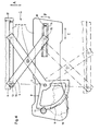
- the cross arm window lifter 1 essentially consists of a base plate 2 attached in the interior of the door, which can also be formed by an assembly carrier or the like, a cross arm arrangement comprising a main arm 3 and an auxiliary arm 4. Shift the upper end points of the cross arm arrangement two guide and lifting rails 105, 105 'attached to the lower transverse edge of a car window pane 106 in the vertical direction A back and forth.
- the main arm 3 is rotatably mounted on the base plate 2 via a bearing pin 7.
- a toothed segment arch 8 is rigidly connected, in particular welded, to the main arm 3 and engages in its external toothing 9 a pinion 11 indicated in FIG. 1 and driven by an electric motor 10, also indicated.
- an electric motor 10 also indicated.
- a hand crank drive can also be provided.
- the free end of the main arm 3 distant from the bearing pin 7 is e.g. connected to the guide and lifting rail 105 via guide rollers or sliders.
- the auxiliary arm 4 is pivoted when the main arm 3 rotates, for which purpose it is rotatably mounted on the rigid component - main arm 3, toothed segment 8 - via a rotary bearing 12.
- pivot bearing 12 is located exactly in the middle of the length of the main arm.
- the auxiliary arm 4 is pivoted when the main arm 3 rotates, for which purpose it is rotatably mounted on the rigid component — main arm 3, toothed segment arch 8 — via the pivot bearing 12.
- the auxiliary arm 4 therefore forms a double-arm lever, one end of which engages the guide and lifting rail 105 'via a spring clip (not shown) which can be displaced horizontally along the rail 105'.
- the other end of the auxiliary arm 4 is guided with a sliding block, a guide roller or the like in the auxiliary rail 14 in the longitudinal direction E of the rail.
- the first spring clip 119 is shown in a sectional side view AA and in Figure 2a in a plan view. It is constructed symmetrically to the axis of the articulation point 13 in the longitudinal direction.
- the first spring clip 119 has spring arms 128, 128 'in its outer regions, each with a lid-shaped shoulder 129, 129'.
- the spring arms 128, 128 ' point downward at an obtuse angle with respect to the spring clip base plane 143.
- At the extreme ends of these spring arms 120, 121 there are recessed surfaces 126, 127 to facilitate the actuation of the spring arms when a zero point adjustment may become necessary.
- Two nose-shaped clip tongues 130, 131 which are bent out at an obtuse angle from the spring clip base plane 143, protrude into the central circular cutout of the first spring clip 119.
- the articulation part 139 (not shown) is attached to them.
- the first spring clip 119 for its attachment to the guide and lifting rail piece 105 'approximately in the area of the resilient bends 132, 132'; 133, 133 'with holding and guide claws 142, 142', 142 ⁇ , 142 ′′′, provided.
- On the spring arms 122, 123 are parallel to the tabs 122 and 123 two more tabs 122 'and 123' to improve the engagement of these spring arms in the locking elements to be described later.
- Figures 3, 3a and 3b the first spring clip 119 is shown in the installed state with the guide and lifting rail piece 105 'and the articulation part in the form of a cylindrical pivot pin 139.
- Figure 3 is a longitudinal section along line BB in Figure 3a.
- the end walls 134, 134' of the guide and lifting rail piece 105 ' In the zero position of the spring clip 119 with respect to the guide and lifting rail piece 105 'embrace lid-shaped shoulders 129, 129' of the spring arms 128, 128 'of the first spring clip 119 the end walls 134, 134' of the guide and lifting rail piece 105 '.
- the nose-shaped clip tongues 130, 131 the articulation part in the form of the cylindrical pivot pin 139, which is attached to the auxiliary arm 4, not shown, is held and rotatably guided.
- the flattened hemisphere 136 of the pivot pin 139 works with a U-shaped profile ( Figure 3b) of the guide and lifting rail piece 105 '. It is over the first spring clip 119 and its guide claws 142, 142 ', 142 '', 142 '''and held in the guide and lifting rail piece 105' via the holding webs 141, 141 '.
- the first and the second spring arms 120, 121 rest in the illustrated zero position of the spring clip 119 with these tabs 122, 122 'and 123, 123' on the profile base of the U-shaped profile. These tabs are therefore not in the recesses 135, 135 'arranged at the base of the U-shaped profile; 137, 137 'engaged.
- the operation of the device for the adjustable fastening of a car window to a window lifting device is as follows: If it turns out due to a new batch of car doors or window panes that the factory setting of the zero position of the first spring clip 119 on the guide and lifting rail piece 105 'no longer leads to an optimal window pane guide in the car door, but rather this is jammed, depending on the clamping direction first spring clip 119 on the guide and lifting rail 105 'horizontally shifted to the right or to the left. For this purpose, the lid-shaped shoulders 129, 129 'must first be lifted off the end walls 134, 134'.
- FIG. 4 corresponds except for the guide and lifting rails 105, 105 ', the window pane 106' and the slider 16 identical to that already described Figure 1.
- the structure and operation of this arrangement are therefore except for the slider 16, which is made of plastic, as above described.
- a second spring clip 19 made of hardened spring steel, shown in FIG. 5 and FIG. 5a, is provided for the above-mentioned possibly necessary displacement of this slide piece in the horizontal direction on the guide and lifting rail 105 '.
- FIG. 5 shows the second spring clip in a sectional side view from the view DD. It has a corrugated shape in its central region and carries at its right end a first spring arm 20 and a second spring arm 21 (FIG. 5a).
- the spring arms 20 and 21 are located on the right and left of the central axis of the second spring clip 19, so that the right end of the spring clip is approximately half slotted.
- Both spring arms have tongue-shaped tabs 22 and 23 bent downward from the material of the second spring clip, which latch into recesses in a continuous guide and lifting rail 5 (FIG. 6) to be described later.
- At the end regions of the spring arms 20 and 21 downward bent barb-shaped bends 24 and 25 are also arranged.
- FIGS. 6, 6a and 6b show an enlarged detail of the upper articulation point 13 of the auxiliary arm 4 shown in FIG. 4 with the slider 16 in the profiled, continuous guide and lifting rail 5 in the installed state with the second spring clip 19.
- FIG. 6 shows the second spring clip 19 shown in section in FIG. 5 together with the slider 16 (FIG. 4) in the installed state in the guide and lifting rail 5.
- the spring clip 19 expresses itself on the one hand with its two wave-shaped bulges 32 and 33 on the slider 16 and on the other hand with the opposite wave-shaped bulge 34 and the spring arm 20 or the spring arm 21 (not shown) on the profiled guide and lifting rail 5.
- the spring arm 20 engages with its bent tab 22 in a first small rectangular recess 35 in the rail 5.
- the sliding piece 16 is pressed against the rail 5 and held and guided in the direction of displacement with the aid of the tongues 30 and 31 (FIG. 6a).
- An extension beyond the tab 22 on the spring arm 20 in the form of the oblique recess surface 26 has a barb-shaped bend 24 behind the end of the rail 5.
- At the other end of the second spring clip 19 there are the centrally arranged further spring arm 28 with a downwardly bent holding and guide tab 29 which engages in a corresponding recess 36 assigned to it.
- the recess 36 represents an adjustment path limitation of the spring clip in the rail 5 and protects during adjustment against sliding of the spring clip 19 and slide 16 out of the reach of the assembly tool into the profile rail.
- Figure 6a shows in section EE a plan view of the detailed view of Figure 6 with the slider 16, the spring clip 19 and the guide and lifting rail 5.
- the first spring arm 20 of the second spring clip 19 engages with its bent tab 22 in the small, shown in dashed lines , rectangular recess 35 of the rail 5.
- the second spring arm 21 comes with its bent tab 23 between the second and third recesses 37 and 38 (also shown in broken lines) to lie on the profile base 40 of the guide and lifting rail 5.
- the distance between the second recess 37 and the third recess 38 corresponds approximately to the width of the recess 35.
- the tongues 30 and 31 of the second spring clip 19 which are inclined along the wall 39, can be seen in engagement with the recess 42, 43 of the slider 16. Due to the inclined position, a particularly good hold of the spring clip in the recesses 42 and 43 of the slide 16 is achieved without the possibility of slipping.
- the intermediate wall 41 of the slider 16 is somewhat thicker than the distance between the two tongues 30 and 31 on the spring clip 19.
- the left-hand end of the spring clip 19 projects with the spring arm 28 and the holding and guide tab 29 into the recess 36 delimiting the adjustment path of the recess 35, 37 and 38.
- FIG. 6b shows a section along the line GG from FIG. 6a.
- the car window 6 is shown broken off anchored in the guide and lifting rail 5.
- the slider 16 slides resiliently within the guideways of the rail 5.
- the second spring clip 19 which presses via its spring arms 20 and 21 against the profile base 40 of the U-shaped rail 5.
- the bent tab 22 of the spring arm 20 falls into the small, rectangular recess 35 of the rail.
- the spring arm 21 arranged under the spring arm 20, on the other hand, is pressed against the bent base 23 on the profile base 40 of the rail. At this point, the tab cannot engage in the small, rectangular recess 37 in the rail.
- the fixation of the second spring clip 19 with the slider 16 was not drawn in this illustration for reasons of clarity.
- FIG. 6a is considered in more detail.
- the hardened spring clip 19 made of spring steel is located in the profile base 40 between the guide and lifting rail designed as a profile rail 5 and the slider 16. On the one hand, it engages with its tongues 30 and 31 behind the wall 39 of the slider 16 and, on the other hand, via its spring arm 20 and the bent-over tab 22 into the recess 35 of the rail 5, shown underneath it in dashed lines.
- this recess 35 is located in the engagement area of the spring arm 21 with its tab 23 two further rectangular recesses 37 and 38, the center distance of which corresponds to twice their width.
- the hook-shaped tool must reach behind the bend 25 of the spring arm 21 to remove the tab 23 Lift out the rectangular recess 37 and at the same time pull the entire second spring clip 19 with the slider 16 to the right until the tab 23 snaps into the recess 38 of the rail 5 shown in broken lines. Only then can the hook-shaped tool be removed from the bend 25 and a renewed attempt to ensure that the window pane runs properly in the guides.
- the spring arm 28 with the holding and guiding tab 29 is located at the rear end of the second spring clip 19, which lugs into a corresponding adjustment path limiting recess 36 intervenes.
- the recess 36 is therefore a little larger than the adjustment path that is possible through the recess 35, 36 and 38.
- the invention is of course not limited to these three setting cases described, but can by Arrangement of further recesses on the profile rail 5 or further spring arms on the second spring clip 19 can be varied in any width and adjustment step subdivision.
Landscapes
- Engineering & Computer Science (AREA)
- Mechanical Engineering (AREA)
- Window Of Vehicle (AREA)
Claims (18)
- Dispositif de fixation réglable d'une vitre de voiture (6, 106) sur un dispositif lève-vitre (1) présentant une pièce d'articulation (136, 16) qui peut être articulée à un rail de guidage et de levage (105, 5) assemblé à la vitre de voiture (6, 106) et qui peut être déplacée horizontalement sur le rail de guidage et de levage (105, 5), caractérisé en ce qu'il existe, entre le rail de guidage et de levage (105, 5) et la pièce d'articulation (136, 16),une agrafe élastique (119, 19) pouvant être fixée à la pièce d'articulation (136, 16) et au rail de guidage et de levage (105, 5) qui comporte plusieurs éléments d'encliquetage (129, 129', 122, 123, 22, 23) dont au moins un élément d'encliquetage (129, 129', 122, 123, 22, 23) peut venir s'encliqueter dans un ou plusieurs éléments d'encliquetage(134, 134', 135, 135', 137, 137', 35, 37, 38) placés horizontalement à une certaine distance les uns des autres sur le rail de guidage et de levage (105, 5), pour permettre le réglage horizontal de l'agrafe élastique (119, 19).
- Dispositif selon la revendication 1, caractérisé en ce que la pièce d'articulation se présente sous forme d'un boulon de pivotement (139) qui est maintenu à son extrémité tournée vers le guidage en forme de U du rail de guidage et de levage (105') par un hémisphère aplati (136) et, à son autre extrémité, par deux languettes de clipsage en forme de nez (130,131) de l'agrafe élastique (119) sur une face conique (138), dans lequel la face conique se prolonge à hauteur du plan de base de l'agrafe élastique (143) sous forme d'un boulon de pivotement cylindrique (139) pour assurer l'entraînement avec articulation du dispositif lève-vitre (1).
- Dispositif selon la revendication 1 ou 2, caractérisé en ce que l'agrafe élastique (119) entoure le rail de guidage et de levage (105') par deux bras élastiques (128, 128') en forme de couvercle sur les parois frontales pourvues de gradins (129, 129') opposés l'un à l'autre et disposés sur leurs côtés longitudinaux, en ce que l'agrafe élastique (119) est maintenue et guidée, d'une part, par les articulations de bras élastique (132, 133) et, d'autre part, par son côté longitudinal opposé (132', 133') par des griffes de maintien et de guidage (142, 142', 142''') sur le rail de guidage et de levage et en ce qu'elle présente au centre deux autres bras élastiques (120, 121) pourvus de pattes (122, 123) opposées dans la direction longitudinale des agrafes élastiques, ces bras pouvant s'engager dans des cavités correspondantes (135, 137) du rail de guidage et de levage (105').
- Dispositif selon la revendication 3, caractérisé en ce que l'agrafe élastique (119) peut être clipsée au moyen de griffes de maintien et de guidage (142, 142') sur des nervures de maintien (141, 141') du rail de guidage et de levage (105').
- Dispositif selon la revendication 3 ou 4, caractérisé en ce que les bras élastiques (120, 121) présentent chacun deux pattes (122, 122', 123, 123') repliées et parallèles qui partent de ceux-ci depuis l'axe de symétrie de l'agrafe élastique, lesdites pattes pouvant s'engager dans des cavités correspondantes (135, 135', 137, 137') du rail de guidage et de levage (105').
- Dispositif selon la revendication 5, caractérisé en ce que l'extrémité libre des pattes (122, 122', 123, 123') est arrondie.
- Dispositif selon une ou plusieurs des revendications précédentes, caractérisé en ce que les languettes de clipsage en forme de nez (130, 131) de l'agrafe élastique (119) présentent deux languettes repliées à angle obtus depuis le plan de base de l'agrafe élastique présentant une bonne résistance et orientées l'une contre l'autre, qui sont repliées à angle aigu sur la surface conique (138) du boulon de pivotement (139).
- Dispositif selon la revendication 7, caractérisé en ce que les languettes de clipsage (330, 131) sont repliées, après le repli à angle aigu, encore une fois à angle obtus dans la direction de la surface hémisphérique (136) du boulon de pivotement (139).
- Dispositif selon une ou plusieurs des revendications précédentes,caractérisé en ce que l'agrafe élastique est montée élastiquement par les quatre angles extérieurs de son plan de base (143) au moyen de replis élastiques (132, 132', 133, 133') dans la direction de la nervure de maintien aplatie (141, 141') du rail de guidage et de levage (105') en forme de U.
- Dispositif selon une ou plusieurs des revendications précédentes, caractérisé en ce que la languette élastique (119) présente, dans sa zone centrale entre les griffes de maintien et de guidage (142, 142'), deux pattes de déplacement (144, 144') en saillie opposées l'une à l'autre par-dessus les nervures de maintien aplaties (141, 141').
- Dispositif selon la revendication 1, caractérisé en ce que la pièce d'articulation se présente sous forme d'un coulisseau connu en soi (16) en matière plastique qui peut se déplacer dans le rail de guidage et de levage (5) tandis que les pattes (22, 23) d'une agrafe élastique (19) assemblées au coulisseau sont disposées sur les bras élastiques (20, 21) faisant saillie au-dessus du coulisseau (16) et coopérant avec des cavités dans le rail de guidage et de levage (5).
- Dispositif selon la revendication 11, caractérisé en ce que l'agrafe élastique (19) est fendue au milieu dans la direction longitudinale jusqu'à un tiers de sa longueur, en ce qu'elle présente deux bras élastiques (20, 21), en ce que chacun de ces bras élastiques (20, 21) présente au moins une patte (22, 23), en ce que les deux pattes (22, 23) sont décalées l'une par rapport à l'autre en direction de déplacement pour des cavités correspondantes (35, 37, 38) tandis que l'agrafe élastique (19) comporte, en outre, deux languettes (30, 31) qui s'engagent dans les cavités (42, 43) du coulisseau (16).
- Dispositif selon la revendication 11 ou 12, caractérisé en ce que la largeur des cavités (35, 37, 38) est à peu près égale à la moitié de leur distance entre axes.
- Dispositif selon la revendication 13, caractérisé en ce que les languettes (30, 31) de l'agrafe élastique (19) s'engageant dans le coulisseau (16) sont séparées l'une de l'autre parallèlement à la paroi du coulisseau (16) en formant entre elles un angle obtus depuis l'agrafe élastique (19) et sont repliées.
- Dispositif selon la revendication 14, caractérisé en ce que les languettes (30, 31) sont disposées à une certaine distance l'une de l'autre sur l'agrafe élastique (19), cette distance étant un peu plus petite que l'épaisseur d'une paroi intermédiaire (41) du coulisseau (16), si bien que l'agrafe élastique (19) peut être clipsée dans le coulisseau (16) au cours du montage au moyen des languettes (30, 31).
- Dispositif selon une ou plusieurs des revendications précédentes 11 - 15, caractérisé en ce que l'agrafe élastique (9) est ondulée.
- Dispositif selon une ou plusieurs des revendications précédentes 11 - 16, caractérisé en ce que les bras élastiques (20, 21) sont disposés a angle obtus sur l'agrafe élastique (19).
- Dispositif selon une ou plusieurs des revendications précédentes 11 - 17, caractérisé en ce que les bras élastiques (20, 21) présentent, à leurs extrémités extérieures, des replis en forme de crochets (24,25).
Applications Claiming Priority (2)
| Application Number | Priority Date | Filing Date | Title |
|---|---|---|---|
| DE3841781 | 1988-12-12 | ||
| DE19883841781 DE3841781C2 (de) | 1987-12-12 | 1988-12-12 | Vorrichtung zur einstellbaren Befestigung einer Autofensterscheibe an einer Fensterhebeeinrichtung |
Publications (2)
| Publication Number | Publication Date |
|---|---|
| EP0373301A1 EP0373301A1 (fr) | 1990-06-20 |
| EP0373301B1 true EP0373301B1 (fr) | 1993-09-22 |
Family
ID=6368973
Family Applications (1)
| Application Number | Title | Priority Date | Filing Date |
|---|---|---|---|
| EP89116170A Expired - Lifetime EP0373301B1 (fr) | 1988-12-12 | 1989-09-01 | Dispositif de fixation réglable d'une vitre de voiture sur un appareil de lève-vitre |
Country Status (3)
| Country | Link |
|---|---|
| EP (1) | EP0373301B1 (fr) |
| DE (1) | DE58905685D1 (fr) |
| ES (1) | ES2045314T3 (fr) |
Families Citing this family (1)
| Publication number | Priority date | Publication date | Assignee | Title |
|---|---|---|---|---|
| FR2690388A1 (fr) * | 1992-04-22 | 1993-10-29 | Rockwell Abs France | Dispositif support de vitre dans un lève-vitre de véhicule automobile et lève-vitre incorporant ce dispositif. |
Family Cites Families (2)
| Publication number | Priority date | Publication date | Assignee | Title |
|---|---|---|---|---|
| US4183178A (en) * | 1978-12-01 | 1980-01-15 | Ford Motor Company | Window glass adjusting device |
| DE3037851C2 (de) * | 1980-10-07 | 1986-12-04 | Brose Fahrzeugteile GmbH & Co KG, 8630 Coburg | Fensterheber, insbesondere für Kraftfahrzeuge |
-
1989
- 1989-09-01 DE DE89116170T patent/DE58905685D1/de not_active Expired - Fee Related
- 1989-09-01 ES ES89116170T patent/ES2045314T3/es not_active Expired - Lifetime
- 1989-09-01 EP EP89116170A patent/EP0373301B1/fr not_active Expired - Lifetime
Also Published As
| Publication number | Publication date |
|---|---|
| EP0373301A1 (fr) | 1990-06-20 |
| DE58905685D1 (de) | 1993-10-28 |
| ES2045314T3 (es) | 1994-01-16 |
Similar Documents
| Publication | Publication Date | Title |
|---|---|---|
| EP0956416B1 (fr) | Dispositif pour fixer une vitre deplacable de fenetre d'automobile sur le systeme de guidage d'un leve-vitre | |
| DE29503036U1 (de) | Vorrichtung zum Verbinden einer Fensterscheibe mit einem Fensterheber | |
| DE2313690C2 (de) | Treibstangenbeschlag für Fenster, Türen od.dgl | |
| EP2270403A1 (fr) | Rail de support | |
| EP3722527A1 (fr) | Dispositif de fixation permettant de fixer des éléments de façade d'une façade à éléments | |
| EP1641993B1 (fr) | Dispositif de deflexion pour leve-vitre de vehicule automobile | |
| DE69408612T2 (de) | Antriebs- und Arretiervorrichtung für Kraftfahrzeugfenster | |
| EP1840314B1 (fr) | Composant coupe-feu | |
| DE3841781C2 (de) | Vorrichtung zur einstellbaren Befestigung einer Autofensterscheibe an einer Fensterhebeeinrichtung | |
| EP1002923A2 (fr) | Dispositif d'ouverture et de fermeture d'une ouverture dans une paroi au moyen d'une porte coulissante | |
| EP0539672B1 (fr) | Ferrure pour fixation dans une rainure d'un profilé rétréci des deux côtés | |
| EP0373301B1 (fr) | Dispositif de fixation réglable d'une vitre de voiture sur un appareil de lève-vitre | |
| EP3667005B1 (fr) | Système de charnière, carrosserie de véhicule, véhicule et procédé de montage d'une porte | |
| DE29514640U1 (de) | Treibstangenbeschlag für Türen, Fenster o.dgl. | |
| DE102007007457B4 (de) | Innenverkleidung für eine Kraftfahrzeugtür | |
| WO2013083265A1 (fr) | Elément de support pour un lève-glace pour véhicule automobile avec structure de renforcement | |
| DE19913306A1 (de) | Beschlagsystem | |
| EP0398196A2 (fr) | Arrêt pour porte à force d'arrêt réglable | |
| DE4321616A1 (de) | Vorrichtung zum Verbinden eines Mitnehmers eines Fensterhebers mit einer Fensterscheibe | |
| DE102009054644B4 (de) | Beschlagteilanordnung für ein Fenster, eine Tür, eine Klappe oder dergleichen | |
| WO2005088053A1 (fr) | Cassette pour la transmission de force dans un leve-vitre | |
| EP3101207B1 (fr) | Dispositif de porte coulissante | |
| DE102005027909B4 (de) | Einrichtung zur Einstellung der Lage einer Führungsschiene für einen Kraftfahrzeugfensterheber | |
| EP1216336B1 (fr) | Element de garniture | |
| DE4434589A1 (de) | Vorrichtung zum Verbinden einer Fensterscheibe mit einem Fensterheber |
Legal Events
| Date | Code | Title | Description |
|---|---|---|---|
| PUAI | Public reference made under article 153(3) epc to a published international application that has entered the european phase |
Free format text: ORIGINAL CODE: 0009012 |
|
| 17P | Request for examination filed |
Effective date: 19890901 |
|
| AK | Designated contracting states |
Kind code of ref document: A1 Designated state(s): DE ES FR GB |
|
| 17Q | First examination report despatched |
Effective date: 19920123 |
|
| GRAA | (expected) grant |
Free format text: ORIGINAL CODE: 0009210 |
|
| AK | Designated contracting states |
Kind code of ref document: B1 Designated state(s): DE ES FR GB |
|
| REF | Corresponds to: |
Ref document number: 58905685 Country of ref document: DE Date of ref document: 19931028 |
|
| GBT | Gb: translation of ep patent filed (gb section 77(6)(a)/1977) |
Effective date: 19931103 |
|
| ET | Fr: translation filed | ||
| REG | Reference to a national code |
Ref country code: ES Ref legal event code: FG2A Ref document number: 2045314 Country of ref document: ES Kind code of ref document: T3 |
|
| PLBE | No opposition filed within time limit |
Free format text: ORIGINAL CODE: 0009261 |
|
| STAA | Information on the status of an ep patent application or granted ep patent |
Free format text: STATUS: NO OPPOSITION FILED WITHIN TIME LIMIT |
|
| 26N | No opposition filed | ||
| PGFP | Annual fee paid to national office [announced via postgrant information from national office to epo] |
Ref country code: GB Payment date: 19990726 Year of fee payment: 11 |
|
| PGFP | Annual fee paid to national office [announced via postgrant information from national office to epo] |
Ref country code: FR Payment date: 19990817 Year of fee payment: 11 |
|
| PGFP | Annual fee paid to national office [announced via postgrant information from national office to epo] |
Ref country code: ES Payment date: 19990914 Year of fee payment: 11 |
|
| PG25 | Lapsed in a contracting state [announced via postgrant information from national office to epo] |
Ref country code: GB Free format text: LAPSE BECAUSE OF NON-PAYMENT OF DUE FEES Effective date: 20000901 |
|
| PG25 | Lapsed in a contracting state [announced via postgrant information from national office to epo] |
Ref country code: ES Free format text: LAPSE BECAUSE OF NON-PAYMENT OF DUE FEES Effective date: 20000902 |
|
| GBPC | Gb: european patent ceased through non-payment of renewal fee |
Effective date: 20000901 |
|
| PG25 | Lapsed in a contracting state [announced via postgrant information from national office to epo] |
Ref country code: FR Free format text: LAPSE BECAUSE OF NON-PAYMENT OF DUE FEES Effective date: 20010531 |
|
| REG | Reference to a national code |
Ref country code: FR Ref legal event code: ST |
|
| PGFP | Annual fee paid to national office [announced via postgrant information from national office to epo] |
Ref country code: DE Payment date: 20011109 Year of fee payment: 13 |
|
| PG25 | Lapsed in a contracting state [announced via postgrant information from national office to epo] |
Ref country code: DE Free format text: LAPSE BECAUSE OF NON-PAYMENT OF DUE FEES Effective date: 20030401 |
|
| REG | Reference to a national code |
Ref country code: ES Ref legal event code: FD2A Effective date: 20011011 |