EP0373331B1 - Procédé et appareil pour manipuler des piles de feuilles de papier dans des machines d'emballage - Google Patents
Procédé et appareil pour manipuler des piles de feuilles de papier dans des machines d'emballage Download PDFInfo
- Publication number
- EP0373331B1 EP0373331B1 EP89119879A EP89119879A EP0373331B1 EP 0373331 B1 EP0373331 B1 EP 0373331B1 EP 89119879 A EP89119879 A EP 89119879A EP 89119879 A EP89119879 A EP 89119879A EP 0373331 B1 EP0373331 B1 EP 0373331B1
- Authority
- EP
- European Patent Office
- Prior art keywords
- path
- commodities
- conveyor
- elevator
- speed
- Prior art date
- Legal status (The legal status is an assumption and is not a legal conclusion. Google has not performed a legal analysis and makes no representation as to the accuracy of the status listed.)
- Expired - Lifetime
Links
- 238000000034 method Methods 0.000 title claims description 18
- 230000010006 flight Effects 0.000 claims description 32
- 230000033001 locomotion Effects 0.000 claims description 22
- 238000012545 processing Methods 0.000 claims description 15
- 230000008859 change Effects 0.000 claims description 9
- 239000000463 material Substances 0.000 claims description 9
- 238000011144 upstream manufacturing Methods 0.000 claims description 5
- 230000001174 ascending effect Effects 0.000 claims description 3
- 230000008878 coupling Effects 0.000 claims description 2
- 238000010168 coupling process Methods 0.000 claims description 2
- 238000005859 coupling reaction Methods 0.000 claims description 2
- 230000007423 decrease Effects 0.000 claims description 2
- 239000012530 fluid Substances 0.000 claims description 2
- 238000006243 chemical reaction Methods 0.000 description 5
- 230000007246 mechanism Effects 0.000 description 4
- 238000012546 transfer Methods 0.000 description 4
- 239000000853 adhesive Substances 0.000 description 3
- 230000001070 adhesive effect Effects 0.000 description 3
- 238000012856 packing Methods 0.000 description 3
- 230000008901 benefit Effects 0.000 description 2
- 230000005540 biological transmission Effects 0.000 description 2
- 238000001514 detection method Methods 0.000 description 2
- 239000011888 foil Substances 0.000 description 2
- 230000005855 radiation Effects 0.000 description 2
- 230000004044 response Effects 0.000 description 2
- 230000003467 diminishing effect Effects 0.000 description 1
- 230000008030 elimination Effects 0.000 description 1
- 238000003379 elimination reaction Methods 0.000 description 1
- 238000009963 fulling Methods 0.000 description 1
- 238000012544 monitoring process Methods 0.000 description 1
- 230000008569 process Effects 0.000 description 1
- 230000000750 progressive effect Effects 0.000 description 1
- 230000009467 reduction Effects 0.000 description 1
- 238000005204 segregation Methods 0.000 description 1
Images


Classifications
-
- B—PERFORMING OPERATIONS; TRANSPORTING
- B65—CONVEYING; PACKING; STORING; HANDLING THIN OR FILAMENTARY MATERIAL
- B65H—HANDLING THIN OR FILAMENTARY MATERIAL, e.g. SHEETS, WEBS, CABLES
- B65H31/00—Pile receivers
- B65H31/30—Arrangements for removing completed piles
- B65H31/3054—Arrangements for removing completed piles by moving the surface supporting the lowermost article of the pile, e.g. by using belts or rollers
-
- B—PERFORMING OPERATIONS; TRANSPORTING
- B65—CONVEYING; PACKING; STORING; HANDLING THIN OR FILAMENTARY MATERIAL
- B65B—MACHINES, APPARATUS OR DEVICES FOR, OR METHODS OF, PACKAGING ARTICLES OR MATERIALS; UNPACKING
- B65B25/00—Packaging other articles presenting special problems
- B65B25/14—Packaging paper or like sheets, envelopes, or newspapers, in flat, folded, or rolled form
-
- B—PERFORMING OPERATIONS; TRANSPORTING
- B65—CONVEYING; PACKING; STORING; HANDLING THIN OR FILAMENTARY MATERIAL
- B65H—HANDLING THIN OR FILAMENTARY MATERIAL, e.g. SHEETS, WEBS, CABLES
- B65H31/00—Pile receivers
- B65H31/30—Arrangements for removing completed piles
- B65H31/3081—Arrangements for removing completed piles by acting on edge of the pile for moving it along a surface, e.g. by pushing
-
- B—PERFORMING OPERATIONS; TRANSPORTING
- B65—CONVEYING; PACKING; STORING; HANDLING THIN OR FILAMENTARY MATERIAL
- B65H—HANDLING THIN OR FILAMENTARY MATERIAL, e.g. SHEETS, WEBS, CABLES
- B65H2301/00—Handling processes for sheets or webs
- B65H2301/40—Type of handling process
- B65H2301/42—Piling, depiling, handling piles
- B65H2301/422—Handling piles, sets or stacks of articles
- B65H2301/4226—Delivering, advancing piles
- B65H2301/42266—Delivering, advancing piles by acting on edge of the pile for moving it along a surface, e.g. pushing
-
- B—PERFORMING OPERATIONS; TRANSPORTING
- B65—CONVEYING; PACKING; STORING; HANDLING THIN OR FILAMENTARY MATERIAL
- B65H—HANDLING THIN OR FILAMENTARY MATERIAL, e.g. SHEETS, WEBS, CABLES
- B65H2701/00—Handled material; Storage means
- B65H2701/10—Handled articles or webs
- B65H2701/17—Nature of material
- B65H2701/176—Cardboard
Definitions
- the Invention relates to a method of and to an apparatus for supplying stacks of paper sheets or similar block-shaped commodities to a processing machine pursuant to the preambles of claims 1 and 5 resp.
- stacks of sheets which are advanced from the sheeter into the wrapper must be transported along an elongated path, and the arrival of stacks into the wrapper must be properly timed to ensure that each stack will reach the wrapping station during a predetermined phase or stage of the respective cycle of the wrapper. This necessitates the provision of a satisfactory infeed apparatus which can control the advancement of successive stacks toward the wrapping station.
- the stacks are normally advanced by a series of successive endless conveyors each of which comprises several discrete tapes trained over pulleys and being driven to advance the stacks along the elongated path.
- tails namely, groups of lowermost sheets which are shifted relative to the sheets above them.
- a tail extends from the rear end face of the respective stack, and its sheets are likely to be damaged or defaced during transport toward the wrapping station.
- Such transport normally involves engagement of the rear end faces of successive stacks by discrete flights of a transfer conveyor which serves to advance successive stacks at predetermined intervals in order to ensure that the stacks will reach the wrapping station during the aforementioned phase or stage of the respective wrapping cycle.
- Vorachek et al. discloses an elevator which is provided at the wrapping station to move successive stacks from a first to a second level while the stack is in the process of being draped into a blank of wrapping material. This involves conversion of the blank into a tube which surrounds the stack on the elevator, and closing of the ends of the tube by suitable tucking and folding instrumentalities in order to convert the tube into a prismatic envelope which completely surrounds and confines the respective stack. Problems arise when the stacks are wrapped at a high frequency because the marginal portions of a blank, which are to overlie each other, in order to convert the blank into a tube, are likely to be flexed and/or otherwise deformed by currents of air at the wrapping station.
- the object of the invention is to provide a novel and improved method of and apparatus for supplying stacks of superimposed paper sheets or other block-shaped commodities toward a processing station, particularly toward a station where the commodities are draped into blanks of wrapping paper, foil or the like, and to provide a method and an apparatus which render it possible to eliminate, or at least reduce the dimensions of, so-called tails which develop during transport of stacked paper sheets along a path wherein the stacks are caused to move from at least one preceding conveyor onto a next-following conveyor with resultant shifting of lowermost sheets relative to the sheets in the upper portions of the stacks.
- One feature of the present invention resides in the provision of a method of supplying stacks of paper sheets or similar block-shaped commodities to a processing machine, particularly to a wrapping machine wherein the commodities are draped into blanks of paper or the like.
- the method is characterised by the steps of transporting a series of spaced-apart flights at a second speed along an endless path a portion of which is located in a predetermined plane (preferably a horizontal plane) and wherein the flights advance in a predetermined direction, and advancing said commodities at a higher first speed in said predetermined direction along said elongated first path which leads toward the processing machine and a portion of which coincides with said portion of the endless path so that the front sides of successive commodities catch up with successive flights and their speed is reduced from the first to the second speed.
- the method under the invention further comprises the steps of disengaging the flights from the respective commodities while the flights and the commodities advance at the same speed, and advancing the commodities along the first path at the second speed.
- the method preferably further comprises the step of changing the orientation of commodities upstream of the aforementioned portion of the first path when the orientation of commodities deviates from a predetermined orientation in which the front and rear sides or end faces of the commodities extend at right angles to the predetermined direction.
- the method can further comprise the steps of moving successive commodities from a first level to a second level subsequent to disengagement of commodities from the respective flights, and draping blanks of wrapping material around successive commodities during movement between the two levels so that each blank is converted into a portion of a tube while moving with the commodity toward the second level.
- the apparatus under the invention is characterised by a second conveyor defining an endless second path including a first portion which coincides with a predetermined portion of the first path and an ascending second portion which precedes said first portion, a plurality of spaced-apart flights on said second conveyor, and means for driving said second conveyor at a second speed which is less than said first speed so that a commodity which advances along said predetermined portion of the first path catches up with and engages a flight in said first portion of the second path and is decelerated by the thus engaged flight.
- the flights are transported at a speed which is less than the speed of the infeed conveyor so that the commodities can catch up with the flights which are located ahead of them.
- the infeed conveyor preferably comprises at least two endless tapes which are disposed in two spaced-apart parallel vertical planes, and each flight preferably includes a portion which is disposed between such planes and extends into the predetermined portion of the first path during movement along the first portion of the second path.
- the apparatus can further comprise a third conveyor defining a third path which is substantially aligned with and is located downstream of the first path, and means for driving the third conveyor at a speed which matches or approximates the speed of the flights. This ensures that the flights can be readily separated from the respective commodities by descending below the level of the third path while the commodities advance toward the processing machine.
- the apparatus can further comprise two novel lead-in conveyors which flank a second portion of the first path ahead of the predetermined portion (i.e., upstream of the first portion of the second path).
- Each lead-in conveyor has an endless flexible belt with an elongated reach adjacent the first path.
- Each such reach includes a front section which extends in the predetermined direction and a rear section which slopes forwardly toward the first path so that the second sections of the two reaches define a tapering channel the width of which decreases in the predetermined direction to thus enable the belts to change the orientation of commodities which lie askew during advancement along the first path.
- the lead-in conveyors further comprise means for driving the belts at a speed which is higher than the speed of the adjacent section of the infeed conveyor.
- the belts are trained about pulleys having axes extending at right angles to the direction of advancement of commodities along the first path.
- the apparatus preferably further comprises sidewalls which flank at least the predetermined portion of the first path, and means for jointly moving the sidewalls and the respective lead-in conveyors transversely of the first path, i.e., for jointly moving the lead-in conveyors toward or away from each other while the sidewalls move toward or away from each other.
- Such adjustments of the positions of lead-in conveyors and sidewalls are necessary when the apparatus is to be converted for advancement and proper orientation of larger or smaller commodities.
- the apparatus can further comprise outer conveyors which are disposed between the sidewalls and the predetermined portion of the first path to support the adjacent lateral portions of commodities which advance toward the third conveyor.
- Means is provided for moving the outer conveyors toward or away from each other transversely of the first path to thereby change the loci of the outer conveyors relative to each other, relative to the first path and preferably also relative to the adjacent sidewalls. This can be achieved by coupling the moving means for the outer conveyors with the means for moving the sidewalls in such a way that the extent of movement of the outer conveyors toward or away from each other is less than the extent of movement of the sidewalls toward or away from each other.
- a stop gate is preferably installed downstream of the lead-in conveyors, and the apparatus then comprises means for moving the stop gate into and from the first path (i.e., into and from the path for the commodities) at predetermined intervals.
- Such moving means can comprise means for monitoring the first path and for generating signals in response to detection of irregularities in the manner of advancement of commodities toward the flights, e.g., when two successive commodities abut each other or are too close to one another.
- the apparatus or the processing machine can further comprise means for draping successive commodities into blanks of paper or the like, and the third conveyor can be designed to advance successive commodities directly to an elevator of the draping means.
- the end portions of the tapes which form part of the infeed conveyor and/or third conveyor are connected to each other by joints which are preferably offset or staggered in the longitudinal direction of the tapes so as to ensure smooth transfer of commodities from the infeed conveyor onto the third conveyor and/or from the third conveyor onto the elevator of the draping means.
- Still another feature of the invention resides in the provision of a draping arrangement which can be embodied in a wrapping machine wherein blanks of paper or the like are draped around stacks of superimposed sheets.
- the improved draping arrangement comprises an elevator which is movable between a lower level and a higher level, conveyor means (such as the aforementioned infeed conveyor or the aforementioned third conveyor) for delivering discrete stacks directly onto the elevator while the elevator is located at the lower level, one or more suction chambers or other suitable means for releasably holding a blank above the stack on the elevator while the elevator is located at the lower level, and means for converting the blank into an envelope which surrounds a substantial part (e.g., nearly four sides) of the stack during movement of the elevator from the lower level to the higher level.
- the arrangement preferably further comprises a stop which is located opposite the conveyor means, and at least one loader finger which is operative to move a stack on the elevator against the stop while the elevator is located at the lower level.
- the converting means preferably comprises choke bars or other suitable means for flexing the marginal portions of the blank along two end faces of the stack on the elevator during movement of the elevator to the upper level, and two underfolders which have means for folding parts of the flexed marginal portions of the blank beneath the raised stack. At least one of the underfolders can be provided with a so-called vacuum bar to attract the respective marginal portion of the blank.
- the stop can be provided with a suction chamber to flex a part of the respective marginal portion of the blank away from the stack during movement of the elevator to the higher level.
- Means e.g., a so-called air bar
- Means can be provided to direct at least one jet of compressed air or another gaseous fluid against the topmost sheet of the stack which is adjacent the elevator while the elevator descends toward the lower level so as to ensure that the topmost sheet or sheets of the stack are not shifted relative to the sheets below by turbulence which is created by the rapidly descending elevator.
- the method and the apparatus according to the invention are to improve the manipulation of block-shaped commodities, particularly stacks of paper sheets or the like, during transport along a path.
- a remarkable advantage of the invention is, that it eliminates tails caused by shifted lowermost sheets, or at least reduces their dimensions.
- a further advantage resides in that it renders it possible to change the orientation of misoriented stacks to adjust their orientation for the next following processing station.
- the invention advantageously provides the possibility for varying the effective width of the path along which the stacks advance between a sheeter and a following processing unit.
- the present invention provides improved method and means for properly transporting block-shaped commodities at high frequency so as to meet the requirements of a modern high-speed processing machine, such as a wrapper for stacks of sheets of paper, foil, cardboard or the like. And advantageously it provides progressive means for draping successively feeded stacks of paper sheets into separated blanks of packing material without damaging the packing material or the sheets of the stacks and without distortion of the configuration of the stacks during draping them into the packing material.
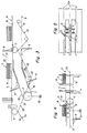
- FIG. 1 there is shown a portion of a processing machine which includes a frame or support 1 for an apparatus having an infeed conveyor 2 for a series of spaced-apart block-shaped commodities 3.
- Each such commodity constitutes a stack of superimposed paper sheets 3a (FIG. 1a) which are advanced in the direction of arrow 4 along an elongated horizontal path A toward an elevator 5 forming part of a wrapping mechanism wherein the commodities (hereinafter called stacks) are draped into blanks 6 (FIG. 6) of paper or other suitable wrapping material.
- the infeed conveyor 2 comprises a first section 2A which has five endless flexible tapes or bands 2a, a second section 2B which partly overlaps the first section 2A and has four endless tapes or bands 2b, and a third section 2C partly overlapping the second section 2B and having three endless tapes or bands 2c.
- the tapes or bands (hereinafter called tapes) of the sections 2A, 2B, 2C are disposed in parallel vertical planes which are spaced apart from each other so that the rearmost portions of the upper reaches or stretches of the tapes 2b can extend into the spaces between the front portions of upper reaches or stretches of the tapes 2a and the rearmost portions of the upper reaches or stretches of the tapes 2c can extend into the spaces between the front portions of upper reaches of the tapes 2b.
- the upper reaches of the tapes 2b are coplanar or substantially coplanar with the upper reaches of the tapes 2a and 2c.
- tail 3b (see FIG. 1a) which normally consists of a few sheets 3a (e.g., up to six sheets).
- tails can also develop during manipulation of stacks ahead of the tapes 2a, for example, in a so-called sheeter 15 a part of which is shown in the left-hand portion of FIG. 2.
- the sheets 3a of the tail 3b are offset relative to each other and/or relative to the sheets 3a forming the major part of the respective stack 3, and the tail extends rearwardly beyond the rear end face 3c of the respective stack.
- the sheets 3a forming the tail 3b are the lowermost sheets of the respective stack 3.
- the front end face 3d and the rear end face 3c of each stack 3 which is properly oriented on the infeed conveyor 2 extend at right angles to the direction (arrow 4) of advancement of stacks with the tapes 2a-2c, and each properly oriented stack 3 extends transversely of such direction, i.e., the front and rear end faces 3d, 3c are longer than the lateral faces 3e and 3f of the stack.
- the apparatus further comprises an endless second conveyor 7 (FIG. 3) which includes two endless tapes or bands 7a and carries a set of uniformly spaced-apart flights 8 which cooperate with the tapes 2c to eliminate or at least reduce the dimensions of tails 3b on stacks 3 in the elongated horizontal path A defined by the infeed conveyor 2.
- the pulleys 9 for the tapes 2c are driven by at least one first prime mover 10 at a first speed
- at least one pulley 11 for the tapes 7a of the second conveyor 7 is driven by a second prime mover 12 at a speed which is less than the first speed.
- the path A which is defined by the infeed conveyor 2 has an elongated portion A1 substantially coinciding with a first portion B1 of the path B which is defined by the second conveyor 7 for the flights 8, and the path B includes an upwardly sloping second portion B2 which merges into and is located ahead of the portions A1 and B1.
- a flight 8 which advances along the path portion B2 toward the path portion B1 gradually enters the path A at a time when it is spaced apart from the rear end face 3c of a stack 3 in the path portion A1 so that it never catches up with such stack.
- the front end face 3d of the stack 3 catches up with and engages the rear side of the preceding flight 8 whereby the tapes 2c begin to move relative to the tail 3b and cause the sheets 3a of the tail to move forwardly (arrow 4) relative to the sheets 3a above the tail.
- the tapes 2c can cover a distance of 22 inches while a flight 8 covers a distance of 18 inches.
- Each flight 8 includes two portions or prongs which are disposed in two vertical planes including the spaces between the tapes 2c of the infeed conveyor section 2c.
- the tapes 2c move forwardly (arrow 4) at a speed which exceeds the speed of the tapes 7a in the path portions B2 and B1 to thus ensure that the stacks 3 move faster than the flights 8 and that the front end faces 3d of the stacks actually engage the flights 8 in front of them whereby the stacks 3 are decelerated and the sheets 3a of the tails 3b move relative to the remaining sheets of such stacks.
- the infeed conveyor 2 is followed by a third conveyor 13 having three endless tapes or bands 13a each of which is coplanar with one of the tapes 2c.
- One of the pulleys 14 for the tapes 13a is driven by the prime mover 12 at the speed of the conveyor 7 so that the tendency of lowermost sheets 3a of a stack 3 to move forwardly relative to the sheets above them is terminated as soon as the stack advances beyond the upper reaches of the tapes 2c and begins to advance with the tapes 13a.
- the tapes 13a transport the stacks 3 all the way to the elevator 5 at the wrapping station.
- the flights 8 are automatically disengaged from the front end faces 3c of the respective stacks 3 when they reach and travel around the right-hand pulley 11 (FIG. 4) for the tapes 7c.
- FIG. 2 shows the left-hand portion of the apparatus of FIGS. 1, 3 and 4, and a portion of a sheeter 15 which serves to supply stacks 3 to the infeed conveyor 2.
- a conveyor 16 (indicated by an arrow) serves to advance a series of successive stacks 3 onto the upper reaches of tapes 2a forming part of the first section 2A of the infeed conveyor 2.
- the tapes 2a of the conveyor section 2A are driven at the speed of the conveyor 16 and can receive motion from the prime mover PM of the sheeter 16.
- the speed of the conveyor 16 and conveyor section 2A is variable.
- FIG. 2 further shows a photoelectronic detector having a radiation source 17a at one side and a transducer 17b at the other side of the conveyor 16.
- the transducer 17b transmits phasing signals which are used to regulate the rate of delivery of stacks 3 to the infeed conveyor 2, for example, in a manner as disclosed in the aforementioned U.S. Pat. No. 4,683,704 to Vorachek et al.
- That portion of the path A which is located ahead of the path portion A1 is flanked by two endless lead-in conveyors 18A, 18B which serve to change the orientation of misoriented stacks 3 on their way toward engagement with the flights 8.
- Each lead-in conveyor has an endless belt conveyor with a substantially V-shaped inner reach 18a backed by a squaring guide 18d and including a front section 18b which extends in parallelism with the direction (arrow 4) of advancement of stacks 3 along the path A, and a rear section 18c which tapers forwardly and inwardly toward the adjacent tape 2b and defines with the other section 18c a channel of diminishing width wherein a misoriented stack 3 is caused to change its orientation and to be properly oriented (so that its end faces 3c, 3d are normal to the direction of arrow 4) not later than on leaving the channel between the sections 18b of the reaches 18a.
- One of the pulleys 19 for each of the lead-in conveyors is driven by a prime mover 20 at a speed which matches the speed of the tapes 2a.
- the pulleys 19 are rotatable about vertical axes.
- the lead-in conveyors 18A, 18B are movable relative to the support 1 together with two elongated sidewalls or guide rails 21A, 21B which flank the path portion A1 and are movable toward and away from each other transversely of the path portion A1 to thereby change the effective width of the path A in the region ahead of the conveyor 13.
- the means for moving the sidewalls 21A, 21B toward and away from each other comprises two rotary knobs 22A, 22B.
- Additional (outer) conveyors 23A, 23B flank the two outer tapes 2c of the infeed conveyor section 2C and are inwardly adjacent the respective sidewalls 21A, 21B.
- These outer conveyors include so-called guide rail tapes and are movable toward and away from each other by either of the two knobs 22A, 22B.
- the knobs 22A, 22B can move the guide rails 21A, 21B at a first rate through the medium of transmissions (note the arrow 24 in FIG. 2), and the conveyors 23A, 23B through the medium of take-off devices (note the arrow 25 in FIG.
- the knob 22A or 22B is rotated by hand in order to change the mutual spacing of the sidewalls 21A, 21B and of the outer conveyors 23A, 23B when the format of the stacks 3 is changed. It is presently preferred to select the ratio of movement of the guide rails 21A, 21B and conveyors 23A, 23B in such a way that the extent of movement of conveyors 23A, 23B toward or away from each other equals or approximates two-thirds of the extent of movement of the sidewalls 21A, 21B toward and away from each other. This has been found to ensure that the lateral portions of stacks 3 which advance between the sidewalls 21A, 21B are properly supported from below in the regions between the outer tapes 2c and the respective sidewalls.
- the transmissions 24 and the take-off devices 25 are shown only symbolically. These parts can constitute a unit which includes suitable links, gears, levers, feed screws, hand wheels and like components enabling an operator to rapidly change the mutual spacing of lead-in conveyors 18A, 18B, sidewalls 21A, 21B and outer conveyors 23A, 23B.
- the conveyors 18A, 23A and the sidewall 22A can be mounted on a first platform 26A which is movable relative to the support 1
- the conveyors 18B, 23B and the sidewall 21B can be mounted on a second platform 26B which is also movable relative to the support 1.
- knobs 22A, 22B are located at opposite sides of the support 1 so as to ensure that adjustments can be carried out at either side of the support.
- the lead-in conveyors 18A, 18b are movable toward and away from each other jointly with the respective sidewalls 21A, 21B.
- the speed of the tapes 2b is less than the speed of the lead-in conveyors 18A, 18B.
- a prime mover 2b′ can drive one of the pulleys 2b ⁇ for the tapes 2b at a speed of 14 inches per cycle.
- the improved apparatus further comprises two stop gates 28A, 28B which are disposed downstream of the respective lead-in conveyors 18A, 18B and are movable by suitable mechanisms 29A, 29B to periodically enter the path A in order to engage the adjacent portions of the front end faces 3d of successive stacks 3 on their way toward the path portion A1.
- stop gates are in use in existing apparatus for advancing stacks of paper sheets to a wrapping station.
- a photoelectric detector including a radiation source 30a and a transducer 30b is provided ahead of the stop gates 28A, 28B in order to transmit signals to the mechanisms 29A, 29B in response to detection of oncoming stacks 3.
- the gates 28A, 28B can be moved into the path A if the orientation of an oncoming stack 3 is unsatisfactory. Reference may be had to the disclosure in U.S. Pat. No. 4,683,704 to Vorachek et al.
- FIG. 5 shows that the joints 31 between the end portions of tapes 13a forming part of the conveyor 13 are offset for smooth transfer of stacks 3 onto the conveyor 13 as well as for equally smooth transfer of stacks from the conveyor 13 onto the elevator 5.
- the conveyor 13 defines an elongated path C which extends all the way to the elevator 5, i.e., the conveyor 13 can deliver successive stacks 3 directly onto the plates 5a of the elevator.
- Loader fingers 33 (FIGS. 5-7) are provided to move along an endless path 32 and to engage the rear end face 3c of a stack 3 on the elevator 5 in order to push the front end face 3d of such stack against a stop plate 34.
- each stack 3 which is about to be lifted by the elevator 5 assumes an optimum position with respect to a blank 6 of wrapping material as well as with respect to several instrumentalities which are provided in the wrapper and serve to convert the blank 6 into an envelope completely confining the stack 3.
- Such confinement namely conversion of the blank 6 into a tube
- the elevator 5 changes the level of the stack 3 by moving it upwardly from the level of FIG. 6 to the level of FIG. 8.
- the manner in which the loader fingers 33 are moved along its endless path 32 departs from the heretofore known manner in that the loader fingers have a variable stroke.
- the arrangement is such that the stroke of the loader fingers 33 is shorter for narrower stacks. This renders it possible to reduce the velocity of loading stacks onto the elevator at higher speeds of the stacks.
- the apparatus comprises means for adjusting the return strokes of loader fingers 33.
- the blank 6 is attracted to the undersides of two suction chambers 35 which are mounted in the frame of the wrapper and flank two choke bars 36 serving to fold the marginal portions of the blank 6 along the front and rear end faces 3d, 3c of a stack 3 which rises with the elevator 5.
- Such lifting of the stack 3 results in folding of the web 6 along the top surface as well as along the front and rear end faces of the stack.
- the marginal portions 6a, 6b of the blank 6 extend downwardly beyond the choke bars 36, and the underside of the marginal portion 6a is provided with a film of a suitable adhesive which causes the marginal portion 6a to adhere to the marginal portion 6b when the conversion of the web 6 into a tube is completed.
- a front underfolder 38 is movable by an arm 38a in directions which are indicted by a double-headed arrow 38b and is provided with a built-in vacuum bar 39 serving to attract the marginal portion 6a of the blank 6 at a level above the film of adhesive while the underfolder 38 moves in a direction to the left (see FIG. 8) in order to fold the marginal portion 6a along the adjacent portion of the underside of the stack 3 on the elevator 5.
- a rear underfolder 40 (which is reciprocable in directions indicated by an arrow 40a) is caused to move to the right and to fold the rear marginal portion 6b of the blank 6 beneath the adjacent portion of the underside of the stack 3.
- the elevator plates 5a are spaced apart from the lifted stack 3 so that the latter rests only on the central elevator platform 5b and on the underfolders 38, 40.
- the platform 5b is then lowered, the underfolder 40 moves to the right beyond the position of FIG. 8 to ensure that the marginal portion 6b is disposed in a horizontal plane, and the underfolder 38 is moved further to the left to cause the marginal portion 6a to underlie and to adhere to the marginal portion 6b. This completes the conversion of the blank 6 into a tube.
- the vacuum bar 39 replaces air bars which are provided in the rear underfolders of conventional wrapping mechanisms.
- An air bar 41 which is built into a guide for the web 6 serves to discharge jets of air which keep the topmost sheet 3a of the stack 3 in place during rapid downward movement of the elevator 5 to the position of FIG. 6. In the absence of the air bar 41, turbulence which is created by the descending elevator 5 could result in shifting of one or more sheets 3a on the adjacent stack 3.
- An air bar 37 of the stop plate 34 discharges one or more jets of air which ensure that the lowermost part of the marginal portion 6a is flexed outwardly and can be properly attracted by the vacuum bar 39 of the front underfolder 38 as the elevator 5 continues to lift the stack 3 which rests on the plates 5a and platform 5b.
- the purpose of the vacuum bar 39 is to maintain the marginal portion 6a away from the elevator 5 and from the rear underfolder 40.
- a conventional means for converting the tube (converted blank 6) into a parallelepiped envelope which completely surrounds the stack 3 comprises a front gripper 42, cover plates 43, pusher plates 44, a rear tucker 45 and overhead flights 46 which provide the open ends of the tube with pairs of tucks and thereupon fold the resulting pairs of flaps over each other in a manner not forming part of the present invention.
- One flap of each pair is provided with a film of adhesive to ensure that the flaps of each pair adhere to each other.
Landscapes
- Engineering & Computer Science (AREA)
- Mechanical Engineering (AREA)
- Separation, Sorting, Adjustment, Or Bending Of Sheets To Be Conveyed (AREA)
- Delivering By Means Of Belts And Rollers (AREA)
- Making Paper Articles (AREA)
Claims (20)
- Procédé destiné à amener des piles (3) de feuilles de papier (3a) ou des produits en forme de bloc similaires vers une machine de traitement, en particulier vers une machine d'emballage, en avançant une série de produits espacés (3) à une première vitesse le long d'une première trajectoire allongée (A) qui conduit à la machine de traitement, caractérisé par les étapes de transport d'une série de poussoirs espacés (8) à une deuxième vitesse le long d'une trajectoire sans fin (B) dont une partie (B1) se trouve dans un plan prédéterminé, et dans lesquels les poussoirs avancent dans une direction prédéterminée (4), et d'avance desdits produits (3) à une première vitesse plus élevée dans ladite direction prédéterminée (4) le long de ladite première trajectoire (A), qui mène à la machine de traitement et dont une partie (A1) coïncide avec ladite partie (B1) de la trajectoire sans fin (B) de telle sorte que les côtés avant (3d) des produits successifs rattrapent des poussoirs (8) successifs et leur vitesse est réduite de la première à la deuxième vitesse.
- Procédé selon la revendication 1, caractérisé par les étapes de désengagement des poussoirs (8) des produits respectifs (3) et d'avance des produits le long de ladite première trajectoire à ladite deuxième vitesse.
- Procédé selon la revendication 1, caractérisé par l'étape de changement de l'orientation des produits (3) en amont de ladite partie (A1) de ladite première trajectoire (A) lorsque l'orientation des produits s'écarte d'une orientation prédéterminée dans laquelle les côtés avant et arrière (3d, 3c) des produits s'étendent perpendiculairement à ladite direction (4).
- Procédé selon la revendication 1, caractérisé par les étapes de désengagement des poussoirs (8) des produits respectifs (3), le déplacement des produits successifs d'un premier niveau (31) à un deuxième niveau différent lors du désengagement des poussoirs respectifs (8), et de mise en place de flans (6) de matière d'emballage autour des produits successifs pendant le déplacement de ces produits entre les niveaux.
- Appareil destiné à amener des piles de feuilles de papier ou autre produits (3) en forme de bloc vers une machine de traitement, en particulier une machine d'emballage, comportant un transporteur d'entrée (2) ayant des moyens destinés à avancer une série de produits espacés dans une direction prédéterminée (4) à une première vitesse le long d'une première trajectoire allongée (A), caractérisé par un deuxième transporteur (7) définissant une deuxième trajectoire sans fin (B) comprenant une première partie (B1) coïncidant avec une partie prédéterminée (A1) de ladite première trajectoire et une deuxième partie ascendante (B2) précédant ladite première partie, plusieurs poussoirs espacés (8) sur ledit deuxième transporteur, et des moyens (12) destinés à entraîner ledit deuxième transporteur (7) à une deuxième vitesse qui est inférieure à ladite première vitesse de sorte qu'un produit (3) qui avance le long de ladite partie prédéterminée (A1) de la première trajectoire (A) rattrape et engage un poussoir (8) dans ladite première partie (B1) de la deuxième trajectoire (B) et est décélérée par le poussoir ainsi engagé.
- Appareil selon la revendication 5, caractérisé en ce que ledit transporteur d'entrée (2) comporte au moins deux bandes sans fin (2b, 2c) qui sont disposées dans deux plans verticaux parallèles espacés et chacun desdits poussoirs (8) comprend une partie qui est disposée entre lesdits plans et s'étend dans ladite partie prédéterminée de ladite première trajectoire (A) pendant le déplacement le long de ladite première partie (B1) de ladite deuxième trajectoire (B).
- Appareil selon la revendication 5, caractérisé par un troisième transporteur (13) définissant une troisième trajectoire qui est sensiblement alignée avec et se trouve en aval de ladite partie prédéterminée (A1) de ladite première trajectoire (A), et des moyens destinés à entraîner ledit troisième transporteur à une vitesse correspondant à ou s'approchant de ladite deuxième vitesse.
- Appareil selon la revendication 5, caractérisé par deux transporteurs d'introduction flexibles sans fin (18A, 18B) bordant une deuxième partie de ladite première trajectoire (A) en avant de la première partie (B1) de ladite deuxième trajectoire (B), chacun desdits transporteurs d'introduction ayant un brin (18a) adjacent à ladite première trajectoire (A) et chaque brin comprenant une section avant (18b) s'étendant dans ladite direction et une section arrière (18c) inclinée vers l'avant en direction de ladite première trajectoire (A) de telle sorte que les deuxièmes sections (18c) desdits brin définissent un canal rétréci dont la largeur diminue dans ladite direction (4) afin de modifier l'orientation des produits (3) qui se trouvent décalés pendant l'avance le long de ladite première trajectoire, et des moyens (20) destinés à entraîner lesdits transporteurs d'introduction.
- Appareil selon la revendication 5, caractérisé par des transporteurs d'introduction (18A, 18B) bordant une deuxième partie de ladite première trajectoire (A) en amont de ladite partie prédéterminée (A1), des parois latérales (21A, 21B) bordant ladite partie prédéterminée de ladite première trajectoire, et des moyens (22A, 22B) destinés à déplacer conjointement lesdites parois latérales et lesdits transporteurs d'introduction transversalement à ladite première trajectoire.
- Appareil selon la revendication 5, caractérisé par des parois latérales (21A, 21B) bordant ladite partie prédéterminée de ladite première trajectoire (A), un transporteur extérieur (23A, 23B) disposé entre chaque paroi latérale et ledit transporteur d'entrée (2B, 2C) afin de supporter des parties des produits (3) qui avancent le long de ladite partie prédéterminée de ladite première trajectoire (A), des moyens (22A, 22B) destinés à déplacer lesdites parois latérales vers et à l'écart l'une de l'autre transversalement à ladite première trajectoire (A) afin de choisir ainsi la largeur effective de ladite partie prédéterminée de la première trajectoire, et des moyens (22A, 22B, 24) destinés à déplacer lesdits transporteurs extérieurs vers et à l'écart l'un de l'autre transversalement à ladite première trajectoire.
- Appareil selon la revendication 10, caractérisé par des moyens (24, 25) destinés à relier lesdits moyens de déplacement (22A, 22B) pour lesdits transporteurs extérieurs (23A, 23B) auxdits moyens de déplacement (22A, 22B) pour lesdites parois latérales (21A, 21B) de telle sorte que l'amplitude de déplacement desdits transporteurs extérieurs l'un par rapport à l'autre est inférieure à la valeur de déplacement desdites parois latérales l'une par rapport à l'autre.
- Appareil selon la revendication 5, caractérisé par des transporteurs d'introduction (18A, 18B) bordant ladite première trajectoire (A) en amont de la première partie (B1) de ladite deuxième trajectoire (B), une partie d'arrêt (28A, 28B) en aval desdits transporteurs d'introduction, et des moyens (29A, 29B) destinés à déplacer ladite partie d'arrêt dans et hors de ladite première trajectoire (A) à un intervalle prédéterminé.
- Appareil selon la revendication 5, caractérisé par un troisième transporteur (13) définissant une troisième trajectoire (C) alignée avec et disposée en aval de ladite partie prédéterminée (A1) de ladite première trajectoire (A), des moyens (12) destinés à entraîner ledit troisième transporteur sensiblement à ladite deuxième vitesse, et des moyens (5, 39, 40) destinés à entourer des produits successifs (3) dans des flans successifs (6) de matière d'emballage, lesdits moyens pour envelopper se trouvant en aval de ladite troisième trajectoire (C) et ayant un élévateur (5) recevant des produits successifs directement dudit troisième transporteur (13).
- Appareil selon l'une des revendications 5 à 13, caractérisé par un troisième transporteur (13) définissant une troisième trajectoire (C) qui est sensiblement alignée avec et se trouve en aval de ladite partie prédéterminée (A1) de ladite première trajectoire (A), et des moyens (12) destinés à entraîner ledit troisième transporteur à une vitesse correspondant à ou s'approchant de ladite deuxième vitesse, au moins un desdits transporteur d'entrée (2) et troisième transporteur (13) comprenant plusieurs bandes flexibles sans fin (2c, 13a) disposées dans des plans parallèles espacés et lesdites bandes ayant des parties d'extrémité et des jonctions (31) raccordant les parties d'extrémité l'une à l'autre, lesdites jonctions étant étagées l'une par rapport à l'autre dans la direction longitudinale desdites bandes.
- Appareil selon l'une des revendications 5 à 14, caractérisé par des moyens (5, 39, 40) destinés à appliquer des flans (6) de papier ou équivalent autour de piles (3) de feuilles superposées, comportant la combinaison d'un élévateur (5) mobile entre un niveau supérieur et un niveau inférieur; des moyens transporteurs (13) destinés à délivrer des piles discrètes (3) directement sur ledit élévateur (5) alors que l'élévateur se trouve au niveau inférieur; des moyens (35) destinés à maintenir de façon amovible un flan (6) au-dessus de la pile sur l'élévateur alors que l'élévateur se trouve au niveau inférieur; et des moyens destinés à convertir les flans en une enveloppe qui entoure une partie substantielle de la pile pendant le déplacement de l'élévateur du niveau inférieur au niveau supérieur.
- Appareil selon la revendication 15, caractérisé par une butée (34) opposée audit troisième transporteur (13) et au moins un doigt de chargement (33) qui agit de façon à déplacer une pile (3) sur ledit élévateur (5) contre ladite butée (34) alors que l'élévateur se trouve audit niveau inférieur.
- Appareil selon la revendication 15, caractérisé en ce que le flan (6) qui est maintenu par lesdits moyens de maintien (35) possède une première partie marginale (6a) s'étendant au-delà d'une face d'extrémité (3d) et une deuxième partie marginale (6b) s'étendant au-delà de l'autre face d'extrémité (3c) de la pile (3) sur ledit élévateur (5) alors que l'élévateur se trouve audit niveau inférieur, lesdits moyens de conversion comportant des moyens (36) destinés à fléchir les parties marginales du flan le long de la face d'extrémité respective de la pile pendant le déplacement de l'élévateur vers le niveau supérieur, et des premier et deuxième dispositifs de pliage par en dessous (38, 40) ayant des moyens destinés à plier des parties des parties marginales fléchies du flan sous la pile soulevée.
- Appareil selon la revendication 17, caractérisé en ce qu'au moins un desdits dispositifs de pliage par en dessous (38) possède des moyens (39) destinés à attirer la partie marginale respective (6a) du flan (6).
- Appareil selon la revendication 17, caractérisé par une butée (34) pour la pile (6) qui est délivrée sur ledit élévateur (5) par lesdits moyens transporteurs (13), ladite butée ayant des moyens (37) destinés à fléchir une partie d'une partie marginale (6a) du flan à l'écart de la pile (3) pendant le déplacement de l'élévateur (5) vers ledit niveau supérieur.
- Appareil selon la revendication 17, caractérisé par des moyens (41) destinés à diriger au moins un jet de fluide gazeux comprimé contre la feuille du dessus (3a) de la pile (3a) qui est adjacente audit élévateur (5) alors que l'élévateur descend vers ledit niveau inférieur.
Applications Claiming Priority (2)
| Application Number | Priority Date | Filing Date | Title |
|---|---|---|---|
| US272125 | 1988-11-16 | ||
| US07/272,125 US5081821A (en) | 1988-11-16 | 1988-11-16 | Method and apparatus for manipulating stacks of paper sheets in wrapping machines |
Related Child Applications (1)
| Application Number | Title | Priority Date | Filing Date |
|---|---|---|---|
| EP93100827.0 Division-Into | 1993-01-21 |
Publications (3)
| Publication Number | Publication Date |
|---|---|
| EP0373331A2 EP0373331A2 (fr) | 1990-06-20 |
| EP0373331A3 EP0373331A3 (en) | 1990-09-05 |
| EP0373331B1 true EP0373331B1 (fr) | 1993-08-04 |
Family
ID=23038512
Family Applications (2)
| Application Number | Title | Priority Date | Filing Date |
|---|---|---|---|
| EP89119879A Expired - Lifetime EP0373331B1 (fr) | 1988-11-16 | 1989-10-26 | Procédé et appareil pour manipuler des piles de feuilles de papier dans des machines d'emballage |
| EP93100827A Ceased EP0547027A1 (fr) | 1988-11-16 | 1989-10-26 | Dispositif pour envelopper des piles de feuilles en papier |
Family Applications After (1)
| Application Number | Title | Priority Date | Filing Date |
|---|---|---|---|
| EP93100827A Ceased EP0547027A1 (fr) | 1988-11-16 | 1989-10-26 | Dispositif pour envelopper des piles de feuilles en papier |
Country Status (3)
| Country | Link |
|---|---|
| US (1) | US5081821A (fr) |
| EP (2) | EP0373331B1 (fr) |
| DE (1) | DE68908120T2 (fr) |
Families Citing this family (21)
| Publication number | Priority date | Publication date | Assignee | Title |
|---|---|---|---|---|
| DE4119511A1 (de) * | 1991-06-13 | 1992-12-17 | Jagenberg Ag | Vorrichtung zum abbremsen von auf einem stapel abzulegenden boegen, insbesondere papier- oder kartonboegen |
| DE4235413A1 (de) * | 1992-10-21 | 1994-04-28 | Bielomatik Leuze & Co | Positioniervorrichtung für Stückgut |
| CH690855A5 (de) * | 1996-05-07 | 2001-02-15 | Grapha Holding Ag | Vorrichtung zum Transportieren von Druckbogen insbesondere in einem Sammelhefter oder in einer Zusammentragmaschine. |
| DE19743978B4 (de) * | 1997-10-06 | 2008-08-21 | Ssb Strapping Systeme Bindlach Gmbh | Vorrichtung zum Transport von Stapeln |
| DE19945114A1 (de) * | 1999-09-21 | 2001-03-22 | Jagenberg Papiertech Gmbh | Vorrichtung zum Querschneiden von Materialbahnen, insbesondere Kartonbahnen |
| US6293544B1 (en) * | 1999-12-22 | 2001-09-25 | Xerox Corporation | Apparatus and method for registering and conveying a compiled set of sheets |
| DE10102590C1 (de) * | 2001-01-20 | 2002-07-11 | Uhlmann Pac Systeme Gmbh & Co | Packguttransportsystem |
| ATE280124T1 (de) * | 2001-09-12 | 2004-11-15 | Segbert Gmbh & Co Kg | Vorrichtung zum ausrichten und abtransportieren von paketen lose gestapelter druckerzeugnisse |
| ITBO20020319A1 (it) * | 2002-05-24 | 2003-11-24 | Tmc Spa | Metodo per il confezionamento di pacchi di rotoli di carta disposti su piu file |
| EP1389592A1 (fr) | 2002-08-13 | 2004-02-18 | Innopack S.r.l. | Dispositif de transport de piles de feuilles de papier ou similaire |
| ITMI20022177A1 (it) | 2002-10-14 | 2004-04-15 | Sitma Spa | Dispositivo e metodo di allineamento di prodotti in |
| US20080315510A1 (en) * | 2007-06-22 | 2008-12-25 | Cary Brzinski | Alignment device for use with a book binder |
| JP2009083962A (ja) * | 2007-09-28 | 2009-04-23 | Canon Inc | シート処理装置及び画像形成装置 |
| DE102008023900A1 (de) * | 2008-05-16 | 2009-11-19 | Wincor Nixdorf International Gmbh | Einrichtung zum Stapeln von Wertscheinen, insbesondere Banknoten |
| CH699597A1 (de) * | 2008-09-29 | 2010-03-31 | Ferag Ag | Fördervorrichtung zum Fördern und Ausrichten von flachen und optional flexiblen Produkten oder von Stapeln von flachen Produkten. |
| ATE501936T1 (de) * | 2008-12-02 | 2011-04-15 | Gd Spa | Verpackungsverfahren und einheit zum falten eines verpackungsmaterialblatts über einen parallelepiped-förmigen artikel |
| ITFI20120172A1 (it) * | 2012-08-30 | 2014-03-01 | Kpl Packaging Spa | "macchina per il confezionamento di prodotti disposti in gruppi ordinati" |
| RU2625964C1 (ru) * | 2013-08-09 | 2017-07-20 | Тотани Корпорейшн | Устройство для заворачивания листового изделия |
| US10797435B2 (en) * | 2014-10-20 | 2020-10-06 | Enphase Energy, Inc. | Method and apparatus for securing a segmented power cable for shipping and storage |
| US10106363B1 (en) * | 2017-08-04 | 2018-10-23 | Packaging Progressions, Inc. | Flap folder |
| CN114735284B (zh) * | 2022-04-28 | 2024-05-10 | 深圳威尔智能系统有限公司 | 标签自动分堆打包方法及装置 |
Family Cites Families (20)
| Publication number | Priority date | Publication date | Assignee | Title |
|---|---|---|---|---|
| US1841714A (en) * | 1929-11-30 | 1932-01-19 | Libbey Owens Ford Glass Co | Sheet glass apparatus |
| US1816085A (en) * | 1930-03-25 | 1931-07-28 | Package Machinery Co | Wrapping machine and process |
| US2488551A (en) * | 1947-08-19 | 1949-11-22 | American Can Co | Sheet feeding and gauging mechanism |
| US2536961A (en) * | 1949-03-28 | 1951-01-02 | George T Smith Inc | Conveyer end connector and gap plate |
| US3000151A (en) * | 1956-05-11 | 1961-09-19 | Berkley Machine Co | Method and apparatus for forming and wrapping packs of envelopes and similar articles |
| US3006119A (en) * | 1960-01-13 | 1961-10-31 | Gen Foods Corp | Wrapping machine |
| GB912327A (en) * | 1960-03-25 | 1962-12-05 | Verpackungs Und Schokoladenmas | Packing machine |
| DE1198288B (de) * | 1961-12-04 | 1965-08-05 | Windmoeller & Hoelscher | Vorrichtung zum schuppenfoermigen Ablegen von zu Stapeln zusammengefassten Schlauchabschnitten aus Papier od. dgl. auf einem Transportband |
| US3198105A (en) * | 1963-11-12 | 1965-08-03 | Signode Corp | Method for aligning and tying stacked bundles |
| US3212230A (en) * | 1965-04-02 | 1965-10-19 | Forgrove Mach | Wrapping machines |
| BE735444A (fr) * | 1968-07-15 | 1969-12-01 | ||
| US3776404A (en) * | 1969-06-17 | 1973-12-04 | Rockwell International Corp | Method of handling books |
| DE2206682B2 (de) * | 1972-02-12 | 1976-09-09 | Windmöller & Hölscher, 4540 Lengerich | Vorrichtung zum bilden und weiterfoerdern von stapeln aus flachen werkstuecken |
| US3964598A (en) * | 1974-04-19 | 1976-06-22 | Strachan & Henshaw Limited | Stacking mechanism and method |
| US4015843A (en) * | 1975-10-14 | 1977-04-05 | Tennant James R | Newspaper streamliner |
| US4381108A (en) * | 1981-06-29 | 1983-04-26 | Newsome John R | Device for aligning signatures fed in shingled relation |
| US4529082A (en) * | 1981-09-28 | 1985-07-16 | Oscar Mayer Foods Corporation | Stack forming method and apparatus |
| US4518300A (en) * | 1982-11-12 | 1985-05-21 | Control Process, Inc. | Take-away technique for sliced bulk products |
| US4683704A (en) * | 1983-10-18 | 1987-08-04 | Pemco, Inc. | Method of and apparatus for wrapping |
| US4667809A (en) * | 1983-10-19 | 1987-05-26 | Trimmer Machine Co., Inc. | Apparatus for aligning signatures |
-
1988
- 1988-11-16 US US07/272,125 patent/US5081821A/en not_active Expired - Lifetime
-
1989
- 1989-10-26 EP EP89119879A patent/EP0373331B1/fr not_active Expired - Lifetime
- 1989-10-26 EP EP93100827A patent/EP0547027A1/fr not_active Ceased
- 1989-10-26 DE DE89119879T patent/DE68908120T2/de not_active Expired - Lifetime
Also Published As
| Publication number | Publication date |
|---|---|
| EP0373331A2 (fr) | 1990-06-20 |
| DE68908120D1 (de) | 1993-09-09 |
| US5081821A (en) | 1992-01-21 |
| EP0373331A3 (en) | 1990-09-05 |
| DE68908120T2 (de) | 1993-12-16 |
| EP0547027A1 (fr) | 1993-06-16 |
Similar Documents
| Publication | Publication Date | Title |
|---|---|---|
| US5081821A (en) | Method and apparatus for manipulating stacks of paper sheets in wrapping machines | |
| JP3868491B2 (ja) | 多数個パックの包装装置 | |
| US4765790A (en) | Apparatus for accumulating stacks of paper sheets and the like | |
| EP1177980B1 (fr) | Machine d'emballage | |
| GB2139176A (en) | Method and apparatus for inserting sheet material into envelopes | |
| US5579895A (en) | Crosspush conveyor for carton loader | |
| US4359214A (en) | Apparatus for feeding flat articles | |
| US12325606B2 (en) | Transfer module for a converting machine | |
| GB2060571A (en) | Device for stacking flat articles such as box blanks | |
| US4524564A (en) | Cartoning method | |
| EP0923497A1 (fr) | Dispositif de maintien a galets pour cartons tronconiques | |
| EP0203397B1 (fr) | Procédé et dispositif pour mettre dans des cartons des unités de piles de papier emballées | |
| US3517482A (en) | Continuous motion mechanical vertical compression apparatus | |
| EP0081628B1 (fr) | Dispositif permettant de grouper et d'empiler un certain nombre d'objets | |
| GB2059380A (en) | Introducing stacks of sheets into prefabricated cartons or the like | |
| US4480422A (en) | Apparatus for packaging stacks of sheet material | |
| GB2065585A (en) | Packaging apparatus | |
| US12492093B2 (en) | Stacker module for a converting machine | |
| US4444383A (en) | Rotary slotter sheet feeder | |
| US4683705A (en) | Method and apparatus for confining wrapped reams of paper sheets in cardboard boxes | |
| JPS5941897B2 (ja) | 連続的に紙シ−トを箱詰めする装置 | |
| GB2349626A (en) | Folding a sleeve-forming sheet around a tray | |
| GB1574895A (en) | Apparatus for depositing sheets |
Legal Events
| Date | Code | Title | Description |
|---|---|---|---|
| PUAI | Public reference made under article 153(3) epc to a published international application that has entered the european phase |
Free format text: ORIGINAL CODE: 0009012 |
|
| AK | Designated contracting states |
Kind code of ref document: A2 Designated state(s): CH DE FR GB IT LI NL SE |
|
| PUAL | Search report despatched |
Free format text: ORIGINAL CODE: 0009013 |
|
| AK | Designated contracting states |
Kind code of ref document: A3 Designated state(s): CH DE FR GB IT LI NL SE |
|
| 17P | Request for examination filed |
Effective date: 19901220 |
|
| 17Q | First examination report despatched |
Effective date: 19920312 |
|
| ITF | It: translation for a ep patent filed | ||
| GRAA | (expected) grant |
Free format text: ORIGINAL CODE: 0009210 |
|
| AK | Designated contracting states |
Kind code of ref document: B1 Designated state(s): CH DE FR GB IT LI NL SE |
|
| XX | Miscellaneous (additional remarks) |
Free format text: TEILANMELDUNG 93100827.0 EINGEREICHT AM 26/10/89. |
|
| REF | Corresponds to: |
Ref document number: 68908120 Country of ref document: DE Date of ref document: 19930909 |
|
| ET | Fr: translation filed | ||
| PLBE | No opposition filed within time limit |
Free format text: ORIGINAL CODE: 0009261 |
|
| STAA | Information on the status of an ep patent application or granted ep patent |
Free format text: STATUS: NO OPPOSITION FILED WITHIN TIME LIMIT |
|
| 26N | No opposition filed | ||
| EAL | Se: european patent in force in sweden |
Ref document number: 89119879.8 |
|
| REG | Reference to a national code |
Ref country code: GB Ref legal event code: IF02 |
|
| PGFP | Annual fee paid to national office [announced via postgrant information from national office to epo] |
Ref country code: NL Payment date: 20081028 Year of fee payment: 20 |
|
| PGFP | Annual fee paid to national office [announced via postgrant information from national office to epo] |
Ref country code: CH Payment date: 20081027 Year of fee payment: 20 Ref country code: DE Payment date: 20081103 Year of fee payment: 20 |
|
| PGFP | Annual fee paid to national office [announced via postgrant information from national office to epo] |
Ref country code: SE Payment date: 20081023 Year of fee payment: 20 Ref country code: IT Payment date: 20081022 Year of fee payment: 20 |
|
| PGFP | Annual fee paid to national office [announced via postgrant information from national office to epo] |
Ref country code: FR Payment date: 20081024 Year of fee payment: 20 |
|
| PGFP | Annual fee paid to national office [announced via postgrant information from national office to epo] |
Ref country code: GB Payment date: 20081028 Year of fee payment: 20 |
|
| REG | Reference to a national code |
Ref country code: CH Ref legal event code: PL |
|
| REG | Reference to a national code |
Ref country code: GB Ref legal event code: PE20 Expiry date: 20091025 |
|
| EUG | Se: european patent has lapsed | ||
| NLV7 | Nl: ceased due to reaching the maximum lifetime of a patent |
Effective date: 20091026 |
|
| PG25 | Lapsed in a contracting state [announced via postgrant information from national office to epo] |
Ref country code: NL Free format text: LAPSE BECAUSE OF EXPIRATION OF PROTECTION Effective date: 20091026 |
|
| PG25 | Lapsed in a contracting state [announced via postgrant information from national office to epo] |
Ref country code: GB Free format text: LAPSE BECAUSE OF EXPIRATION OF PROTECTION Effective date: 20091025 |