EP0373336A1 - Pièce d'insertion pour chaussure - Google Patents
Pièce d'insertion pour chaussure Download PDFInfo
- Publication number
- EP0373336A1 EP0373336A1 EP89120182A EP89120182A EP0373336A1 EP 0373336 A1 EP0373336 A1 EP 0373336A1 EP 89120182 A EP89120182 A EP 89120182A EP 89120182 A EP89120182 A EP 89120182A EP 0373336 A1 EP0373336 A1 EP 0373336A1
- Authority
- EP
- European Patent Office
- Prior art keywords
- insert
- sole
- shoe
- profile
- insert according
- Prior art date
- Legal status (The legal status is an assumption and is not a legal conclusion. Google has not performed a legal analysis and makes no representation as to the accuracy of the status listed.)
- Granted
Links
- 210000004744 fore-foot Anatomy 0.000 claims abstract description 28
- 239000000463 material Substances 0.000 claims description 66
- 210000002683 foot Anatomy 0.000 claims description 39
- 239000004033 plastic Substances 0.000 claims description 25
- 229920003023 plastic Polymers 0.000 claims description 25
- 239000002131 composite material Substances 0.000 claims description 17
- 150000001875 compounds Chemical class 0.000 claims description 12
- 238000005096 rolling process Methods 0.000 claims description 12
- 229910000639 Spring steel Inorganic materials 0.000 claims description 8
- 239000002184 metal Substances 0.000 claims description 8
- 229910052751 metal Inorganic materials 0.000 claims description 8
- 210000001255 hallux Anatomy 0.000 claims description 7
- 230000005540 biological transmission Effects 0.000 claims description 6
- 229910000831 Steel Inorganic materials 0.000 claims description 5
- 239000000945 filler Substances 0.000 claims description 5
- 239000010959 steel Substances 0.000 claims description 5
- 239000007921 spray Substances 0.000 claims description 2
- 238000005507 spraying Methods 0.000 claims description 2
- 239000012858 resilient material Substances 0.000 claims 1
- 238000005452 bending Methods 0.000 abstract description 11
- 239000010410 layer Substances 0.000 description 22
- 230000008901 benefit Effects 0.000 description 7
- 229940126639 Compound 33 Drugs 0.000 description 5
- PNUZDKCDAWUEGK-CYZMBNFOSA-N Sitafloxacin Chemical compound C([C@H]1N)N(C=2C(=C3C(C(C(C(O)=O)=CN3[C@H]3[C@H](C3)F)=O)=CC=2F)Cl)CC11CC1 PNUZDKCDAWUEGK-CYZMBNFOSA-N 0.000 description 5
- 230000000386 athletic effect Effects 0.000 description 4
- 206010065433 Ligament rupture Diseases 0.000 description 3
- 210000003423 ankle Anatomy 0.000 description 3
- 238000010276 construction Methods 0.000 description 3
- 238000005187 foaming Methods 0.000 description 3
- 238000004519 manufacturing process Methods 0.000 description 3
- 230000007704 transition Effects 0.000 description 3
- 239000004809 Teflon Substances 0.000 description 2
- 229920006362 Teflon® Polymers 0.000 description 2
- 208000027418 Wounds and injury Diseases 0.000 description 2
- 238000004026 adhesive bonding Methods 0.000 description 2
- 238000004873 anchoring Methods 0.000 description 2
- 238000005266 casting Methods 0.000 description 2
- 230000006378 damage Effects 0.000 description 2
- 238000009826 distribution Methods 0.000 description 2
- 230000000694 effects Effects 0.000 description 2
- 229920002457 flexible plastic Polymers 0.000 description 2
- 230000006872 improvement Effects 0.000 description 2
- 208000014674 injury Diseases 0.000 description 2
- 230000035515 penetration Effects 0.000 description 2
- 230000009467 reduction Effects 0.000 description 2
- 238000007493 shaping process Methods 0.000 description 2
- 210000003371 toe Anatomy 0.000 description 2
- 238000004073 vulcanization Methods 0.000 description 2
- 229910000838 Al alloy Inorganic materials 0.000 description 1
- 241001295925 Gegenes Species 0.000 description 1
- 239000000853 adhesive Substances 0.000 description 1
- 230000001070 adhesive effect Effects 0.000 description 1
- 230000015572 biosynthetic process Effects 0.000 description 1
- 230000001413 cellular effect Effects 0.000 description 1
- 230000008859 change Effects 0.000 description 1
- 238000007765 extrusion coating Methods 0.000 description 1
- 239000006260 foam Substances 0.000 description 1
- -1 for example Substances 0.000 description 1
- 239000003292 glue Substances 0.000 description 1
- 238000007373 indentation Methods 0.000 description 1
- 210000003041 ligament Anatomy 0.000 description 1
- 239000006223 plastic coating Substances 0.000 description 1
- 229920000642 polymer Polymers 0.000 description 1
- 230000002787 reinforcement Effects 0.000 description 1
- 230000035939 shock Effects 0.000 description 1
- 239000002356 single layer Substances 0.000 description 1
- 239000002689 soil Substances 0.000 description 1
- 239000010935 stainless steel Substances 0.000 description 1
- 229910001220 stainless steel Inorganic materials 0.000 description 1
- 208000008918 voyeurism Diseases 0.000 description 1
- 238000003466 welding Methods 0.000 description 1
Images




Classifications
-
- A—HUMAN NECESSITIES
- A43—FOOTWEAR
- A43B—CHARACTERISTIC FEATURES OF FOOTWEAR; PARTS OF FOOTWEAR
- A43B7/00—Footwear with health or hygienic arrangements
- A43B7/14—Footwear with health or hygienic arrangements with foot-supporting parts
- A43B7/1405—Footwear with health or hygienic arrangements with foot-supporting parts with pads or holes on one or more locations, or having an anatomical or curved form
- A43B7/1415—Footwear with health or hygienic arrangements with foot-supporting parts with pads or holes on one or more locations, or having an anatomical or curved form characterised by the location under the foot
- A43B7/1425—Footwear with health or hygienic arrangements with foot-supporting parts with pads or holes on one or more locations, or having an anatomical or curved form characterised by the location under the foot situated under the ball of the foot, i.e. the joint between the first metatarsal and first phalange
-
- A—HUMAN NECESSITIES
- A43—FOOTWEAR
- A43B—CHARACTERISTIC FEATURES OF FOOTWEAR; PARTS OF FOOTWEAR
- A43B13/00—Soles; Sole-and-heel integral units
- A43B13/02—Soles; Sole-and-heel integral units characterised by the material
- A43B13/10—Metal
-
- A—HUMAN NECESSITIES
- A43—FOOTWEAR
- A43B—CHARACTERISTIC FEATURES OF FOOTWEAR; PARTS OF FOOTWEAR
- A43B13/00—Soles; Sole-and-heel integral units
- A43B13/02—Soles; Sole-and-heel integral units characterised by the material
- A43B13/12—Soles with several layers of different materials
-
- A—HUMAN NECESSITIES
- A43—FOOTWEAR
- A43B—CHARACTERISTIC FEATURES OF FOOTWEAR; PARTS OF FOOTWEAR
- A43B13/00—Soles; Sole-and-heel integral units
- A43B13/14—Soles; Sole-and-heel integral units characterised by the constructive form
- A43B13/141—Soles; Sole-and-heel integral units characterised by the constructive form with a part of the sole being flexible, e.g. permitting articulation or torsion
-
- A—HUMAN NECESSITIES
- A43—FOOTWEAR
- A43B—CHARACTERISTIC FEATURES OF FOOTWEAR; PARTS OF FOOTWEAR
- A43B13/00—Soles; Sole-and-heel integral units
- A43B13/14—Soles; Sole-and-heel integral units characterised by the constructive form
- A43B13/18—Resilient soles
- A43B13/181—Resiliency achieved by the structure of the sole
- A43B13/183—Leaf springs
-
- A—HUMAN NECESSITIES
- A43—FOOTWEAR
- A43B—CHARACTERISTIC FEATURES OF FOOTWEAR; PARTS OF FOOTWEAR
- A43B13/00—Soles; Sole-and-heel integral units
- A43B13/38—Built-in insoles joined to uppers during the manufacturing process, e.g. structural insoles; Insoles glued to shoes during the manufacturing process
-
- A—HUMAN NECESSITIES
- A43—FOOTWEAR
- A43B—CHARACTERISTIC FEATURES OF FOOTWEAR; PARTS OF FOOTWEAR
- A43B5/00—Footwear for sporting purposes
-
- A—HUMAN NECESSITIES
- A43—FOOTWEAR
- A43B—CHARACTERISTIC FEATURES OF FOOTWEAR; PARTS OF FOOTWEAR
- A43B5/00—Footwear for sporting purposes
- A43B5/001—Golf shoes
-
- A—HUMAN NECESSITIES
- A43—FOOTWEAR
- A43B—CHARACTERISTIC FEATURES OF FOOTWEAR; PARTS OF FOOTWEAR
- A43B5/00—Footwear for sporting purposes
- A43B5/04—Ski or like boots
- A43B5/0411—Ski or like boots for cross-country
-
- A—HUMAN NECESSITIES
- A43—FOOTWEAR
- A43B—CHARACTERISTIC FEATURES OF FOOTWEAR; PARTS OF FOOTWEAR
- A43B7/00—Footwear with health or hygienic arrangements
- A43B7/14—Footwear with health or hygienic arrangements with foot-supporting parts
- A43B7/1405—Footwear with health or hygienic arrangements with foot-supporting parts with pads or holes on one or more locations, or having an anatomical or curved form
- A43B7/1415—Footwear with health or hygienic arrangements with foot-supporting parts with pads or holes on one or more locations, or having an anatomical or curved form characterised by the location under the foot
- A43B7/1435—Footwear with health or hygienic arrangements with foot-supporting parts with pads or holes on one or more locations, or having an anatomical or curved form characterised by the location under the foot situated under the joint between the fifth phalange and the fifth metatarsal bone
-
- A—HUMAN NECESSITIES
- A43—FOOTWEAR
- A43B—CHARACTERISTIC FEATURES OF FOOTWEAR; PARTS OF FOOTWEAR
- A43B7/00—Footwear with health or hygienic arrangements
- A43B7/14—Footwear with health or hygienic arrangements with foot-supporting parts
- A43B7/1405—Footwear with health or hygienic arrangements with foot-supporting parts with pads or holes on one or more locations, or having an anatomical or curved form
- A43B7/1415—Footwear with health or hygienic arrangements with foot-supporting parts with pads or holes on one or more locations, or having an anatomical or curved form characterised by the location under the foot
- A43B7/144—Footwear with health or hygienic arrangements with foot-supporting parts with pads or holes on one or more locations, or having an anatomical or curved form characterised by the location under the foot situated under the heel, i.e. the calcaneus bone
-
- A—HUMAN NECESSITIES
- A43—FOOTWEAR
- A43B—CHARACTERISTIC FEATURES OF FOOTWEAR; PARTS OF FOOTWEAR
- A43B7/00—Footwear with health or hygienic arrangements
- A43B7/14—Footwear with health or hygienic arrangements with foot-supporting parts
- A43B7/1405—Footwear with health or hygienic arrangements with foot-supporting parts with pads or holes on one or more locations, or having an anatomical or curved form
- A43B7/1415—Footwear with health or hygienic arrangements with foot-supporting parts with pads or holes on one or more locations, or having an anatomical or curved form characterised by the location under the foot
- A43B7/145—Footwear with health or hygienic arrangements with foot-supporting parts with pads or holes on one or more locations, or having an anatomical or curved form characterised by the location under the foot situated under the toes, i.e. the phalanges
Definitions
- the invention relates to an insert for a shoe, in particular for a sports shoe, which extends at least in the forefoot area, preferably in the entire foot area, of the sole.
- the invention also relates to a sole provided with such an insert and to a shoe having such a sole.
- the wearer of such a shoe with a very thin and stiff sole could stand well and safely on level ground, i.e. such a shoe would give the wearer good stability on level ground, however, the wearer of such a shoe could walk poorly and unsafe with this shoe, and furthermore he would not have good stability on uneven ground because the rigid sole of such a shoe would do not adapt to an uneven floor and make it impossible for the sole of the shoe to roll while walking on the floor.
- the sole of the shoe In order to enable the wearer of the shoe to walk well and safely by a good rolling movement of the sole of the shoe on the floor, the sole of the shoe must be soft and flexible.
- British patent specification GB-A-1 257 524 discloses a spiked stiffening insert made of metal or plastic material which is embedded in the sole of the shoe and is intended in particular for golf shoes.
- the task underlying this stiffening insert is to solve the problems of holding the spikes and isolating the foot from the pressure of the spikes when using lighter, softer and more flexible cellular sole materials.
- an uncontrolled bending of the shoe, in particular an uncontrolled torsional bending of the middle part can be avoided in order to avoid a reduction in the comfort of the foot and an early deformation of the upper shoe.
- the generally flat insert extends over the entire length of the shoe sole and all spikes of the forefoot area are attached to it, the attachment points of the spikes forming slight indentations on the insert.
- This stiffening insert therefore not only achieves the desired transverse reinforcement in the forefoot area of the shoe sole, but at the same time the forefoot area is also stiffened in the longitudinal direction of the sole, which undesirably complicates the rolling movement of the shoe sole when running.
- a stiffening insert made of metal is known from US Pat. No. 4,439,937, which extends from the central part of the forefoot area of the shoe sole backwards to the rear end of the heel area and has the function of a support in the joint or instep area to build.
- the front part of the forefoot area of the shoe sole is expressly released from the stiffening insert so that it remains vertically flexible, as is necessary for a good rolling movement, but this has the disadvantageous consequence that there is little lateral stability here.
- the stiffening insert which in the embodiment of interest extends over practically the entire length of the shoe sole, is designed and inserted into the shoe sole in such a way that the toe area for supporting a toe steel cap and the joint area for supporting the ankle each directly under the insole In contrast, the remaining part of the forefoot area and the heel area of this insert are deepened so that they can be covered continuously by a layer of soft elastic sole material, in order to improve foot comfort in the ball and heel area compared to the use of a stiffening insert that can be used directly anywhere stretches under the insole.
- These recessed areas of the stiffening insert are formed in that the material of the insert at the transition from the respective raised to the respective recessed area is bent in a step-like manner along bending lines which run transversely to the longitudinal axis of the sole.
- these bending lines do not significantly change the stiffness of the insert, so that the insert stiffens the sole in practically the same extent in the transverse and in the longitudinal direction, and thereby the rolling movement of the shoe sole is hindered to the extent that the transverse stiffness is increased.
- the object of the invention is, in particular, to provide an insert for the production of shoes in which the risk of the foot bending sideways and thus the risk of ligament tears and strains is as low as possible and which at the same time has an excellent running movement of the Allow shoe sole with optimal stability.
- the invention is intended to provide a shoe sole and a shoe, in particular a sports shoe, with these properties.
- This object is achieved according to the invention with an insert which extends at least in the forefoot area, preferably in the entire area of the sole, in that the insert is rigid at least in the forefoot area in the transverse direction of the sole, in particular in the respective rolling area of the sole, but vertically in the longitudinal direction of the sole is flexible.
- a sole according to the invention for a shoe is characterized in that it has an insert according to the invention, which is preferably firmly connected to the sole, preferably by foaming, extrusion coating, casting or other shaping with or vulcanizing into a plastic material, the forms at least part of the sole or the entire sole.
- the invention provides a shoe which has a sole according to the invention which has an insert according to the invention.
- a particularly preferred embodiment of the insert according to the invention is characterized in that the insert extends over substantially the entire length of the sole and is well twistable in the longitudinal direction of the sole from the heel to the big toe.
- Such an insert enables twisting movements of the foot, as are required, for example, in many athletics sports, golf, tennis and the like.
- the insert according to the invention is very particularly preferably designed to be elastically resilient, as a result of which the sole of the shoe always returns to its original position on its own.
- the insert according to the invention in its particularly preferred embodiment, is designed to be pressure-resistant perpendicular to the sole plane, which is very important because it causes selective pressures from the floor to be distributed over the entire surface of the insert, so that pressures from small stones, uneven floors o. The like. Do not selectively transfer to the sole of the foot.
- a very particularly preferred and highly practicable embodiment of the insert according to the invention which has all the advantageous features mentioned above, is characterized in that the, in particular one-piece, insert consists of hard, resilient plate material and at least in the forefoot area, preferably over essentially the entire sole area, has a transverse profile, in particular perpendicular, to the longitudinal direction of the sole, which preferably extends over the entire insert width, the hard, resilient plate material preferably being metal and / or plastic plate material, preferably steel sheet, particularly preferably spring steel sheet.
- the high lateral stability of the insert according to the invention in Combined with the good pressure distribution, a very flat design of the shoe soles provided with it, ie the production of thin soles without a significant tipping effect, since the tipping moment is as small as possible due to the low thickness of the sole and the resistance moment against tipping due to the high lateral stability as large as possible, while at the same time providing a high level of comfort for the foot, since punctual pressures from the floor are not transferred to the sole of the foot and the foot is able to roll slightly while running, and furthermore a thin one to adapt to uneven floors A layer of soft, elastic sole material on the underside of the insert is sufficient (high stability).
- An insert designed as a one-piece, profiled plate, in particular with a sole-shaped outline, can be produced as such efficiently and inexpensively on the one hand, and on the other hand it can also be integrated rationally and inexpensively into the sole of a shoe.
- the insert according to the invention is produced from a composite layer material that consists of different material layers, such as metal and plastic.
- it can consist of separate strip-shaped regions in the transverse direction of the sole, which are connected to one another in an articulated manner by the plastic layer.
- the ability of the insert to twist from the heel to the big toe can be increased if the insert has a longitudinal profile in the longitudinal direction of the sole instead of the transverse profile in the joint area and / or in the heel area. Such longitudinal profiling is also advantageous in the joint area for supporting the ankle.
- the insert it is preferable to design the insert so that it extends over substantially the entire area of the sole, it may also be sufficient in some cases if the insert extends over essentially the entire width and / or extends over substantially the entire length of the forefoot area, since most of the advantages set out above are thereby achieved.
- the hard, resilient plate material can have a thickness between 0.1 mm and 1.5 mm, preferably between 0.3 mm and 0.8 mm.
- the transverse and / or longitudinal profiling can be, in particular in cross-section, groove, groove, rib, groove, wave, corrugated or bead-shaped, preferably meandering, trapezoidal, zigzag-shaped or meandering.
- the direction of the profiling is understood here to mean the direction in which such a profiling is rolled, drawn, extruded or the like, that is to say, for example in the case of a profiling which is grooved in cross section, the longitudinal direction of the groove of an individual groove.
- the width is preferably periodically again fetching profile cross-sectional elements 3 mm to 20 mm, preferably 6 mm to 16 mm, particularly preferably 8 mm to 13 mm.
- the insert according to the invention already has an excellent anchoring ability because of the profiling per se and therefore does not need such an increase in the vast majority of cases, to design the profiling so that it is in the direction of profiling is corrugated, serrated, grooved, grooved or corrugated or has another secondary profile running transversely to the direction of profiling.
- the insert in particular if it is designed as a one-piece plate, can have a depression directed towards the floor in a predetermined foot area or in a plurality of predetermined foot areas, and preferably in this area the big toe, the ball of the foot and / or the heel, this depression, so that it fulfills the above-mentioned function particularly well, preferably has a flat or flat depression bottom.
- the insert can be provided with through holes for the plastic material, which are distributed over the surface of the insert, preferably with one or more spray channels for spraying the plastic material through and / or with a plurality or a plurality of through openings which can be breakthroughs in particular.
- the insert according to the invention allows it to be excellent In such a way that knobs or spikes are non-releasably attached or can be exchangeably attached via fastening means which are provided on or in the insert. This practically eliminates all mounting and fastening problems that otherwise arise when attaching knobs or spikes to a normal sole.
- the aforementioned fastening means can be threaded holes provided in the insert or threaded inserts attached to the insert.
- a particularly stable, in particular directionally stable, attachment of the knobs or spikes to the insert can be achieved according to the invention in that the foot parts of the knobs or spikes or the fastening means, such as threaded inserts, are fastened in depressions in the insert and are supported on the side walls of the depressions, preferably fit positively with the adjacent side walls of the depressions and / or are firmly attached to these side walls, these depressions preferably being the profile depressions formed by the transverse and / or longitudinal profiling.
- the spikes can also be attached in other ways, e.g. by riveting or welding.
- the insert according to the invention can also consist of a composite panel material which has several layers combined to form an integrated composite structure, of which at least one layer has the transverse profile, preferably consists of the transverse profile.
- a composite panel material which has several layers combined to form an integrated composite structure, of which at least one layer has the transverse profile, preferably consists of the transverse profile.
- the composite panel material can have a first layer, which consists of a flat, preferably non-profiled, flexible, resilient panel material, and a second layer, which is designed as a profile layer and consists, for example, of individual profiles arranged next to one another, which are connected to the resilient plate material by gluing, vulcanization or the like, so that the first and second layers are integrated into a composite material.
- a first layer which consists of a flat, preferably non-profiled, flexible, resilient panel material
- a second layer which is designed as a profile layer and consists, for example, of individual profiles arranged next to one another, which are connected to the resilient plate material by gluing, vulcanization or the like, so that the first and second layers are integrated into a composite material.
- This type of construction makes it possible to use a particularly resiliently flexible and thin material, for example Teflon or particularly thin spring steel, for the first layer, which has the function of an elastic joint connection of the profiles, on the other hand for that of the second layer, which in particular the The function is to give the insert a high degree of lateral stability, to use a particularly stiff and pressure-resistant material, such as, for example, stainless steel or rigid plastic material.
- a particularly resiliently flexible and thin material for example Teflon or particularly thin spring steel
- an insert according to the invention By means of a composite plate material it is also possible to give the insert according to the invention special special properties which cannot be achieved or can only be achieved with great difficulty with a single-layer plate material.
- an insert that allows only the sole to bend upwards, but not downwards, can be obtained as a transverse profile in a composite panel material by closely arranged rectangular profiles or U-profiles, which gives football shoes, for example, particularly good shooting properties.
- the insert according to the invention can in principle also be used as an "insole” or as an inserted midsole, it is preferably designed as an insole or firmly connected to the sole in order to integrate it stably into the overall structure of the sole and thus of the entire shoe, which is achieved by both Glue to the sole or vulcanize on or in the Sole can also be done by reshaping the insert with sole material.
- the insert according to the invention can be designed as an insole according to the invention in that the profiling cavities or interspaces of the transverse profiling and the longitudinal profiling optionally provided in certain embodiments as well as other depressions or the like. are filled by a filler material, preferably permanently connected to the insert, in such a way that the insert and filler material are preferably combined to form a composite material, the upper and / or lower surface of which is flat.
- the invention further provides a sole for a shoe which has an insert according to the invention which is firmly connected to the sole or forms a part of the sole, or in which the sole is an insole of the type specified above or is fixed to an insole such insole is connected.
- the insert can be foamed with plastic, overmolded, cast or otherwise formed or vulcanized into a plastic material, this plastic material forming at least part of the sole or the filling compound or the entire filling compound.
- insole or sole practically all types of shoes can be provided, the term "shoes" within the scope of the present description and claims also including boots, in particular shaft boots, rubber boots and the like, in addition to shoes in the narrower sense, such as for example, low shoes, high shoes and the like. includes.
- the shoes can be manufactured very inexpensively by using the insert, insole or sole according to the invention.
- the high lateral stability of the insert, insole or sole according to the invention provides advantages for all shoes, support and protection of the arch of the foot and protection in the ball area, in particular also against burning when running, the elastic resilience of the insert causing, inter alia, that the foot less tired.
- the insert, insole or sole according to the invention is advantageous for normal shoes, such as street or running shoes, and it is particularly advantageous for sports shoes, such as in particular, but by no means exclusively, for athletic shoes, jogging shoes, indoor sports shoes, sports shoes for lawn sports, golf shoes , Tennis shoes, high jump shoes, mountain shoes and. Like. And because of the excellent properties it gives the shoe, not only use-promoting and health-protecting, but also performance-enhancing effects that result from the individual properties, such as increased stability, connectivity, elastic resilience, etc. To give just one example, golf shoes have, among other things, an improved impact quality due to the improved stability, the high Rolling mobility and good torsional ability. Trials have shown that a higher jump height can be achieved with a high jump.
- FIG. 1 shows a top view of a first embodiment of an insert 1 according to the invention.
- This insert is made in one piece from hard, resilient plate material, preferably from spring steel, and extends over the entire sole area, that is to say it essentially has the outline of an insole, as shown.
- the insert 1 is provided over its entire surface with a transverse profile which extends in the transverse direction Q of the sole and perpendicular to the longitudinal direction L of the sole.
- a partial perspective view of this transverse profile 2 is illustrated in the lower left part of FIG. 1.
- this transverse profiling has a trapezoidal meander profile with rounded profile edges 3.
- These profile edges 3 are shown in FIG. 1 to characterize the profile direction and the profile period P, the distance between two profile edges 3 shown in FIG. 1 corresponding to half the profile period 1/2 P, since the flanks of the trapezoidal transverse profile 2 differ only slightly from the vertical, so that the two profile edges 3, which each delimit a profile flank, practically coincide into a line from above in the view of FIG. 1.
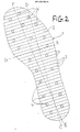
- FIG. 2 shows a further embodiment of an insert 1, which differs from the insert according to FIG. 1 essentially in that the transverse profiling 2 has a larger profile period P and that the insert is provided with through openings 4, which are designed in particular as openings .
- These through openings 4, which are distributed over the surface of the insert 1, serve as through openings for plastic material during foaming, overmolding, casting or other shaping of the insert with plastic for the purpose of integrating the insert into a shoe sole.
- the transverse profile 2 of the insert 1 according to FIG. 2 preferably has the profile shape shown in FIG. 1, below, but it can also have a different profile shape, for example one of the profile shapes shown in FIGS. 4, 5 and 6.
- FIGS. 4, 5 and 6 show partial perspective views of profiles which, instead of the profile shown at the bottom left in FIG. 1, are given as cross-profile 2 and / or longitudinal profile 8 and if transition profiling 9 can be used. It should be pointed out here that the profiles shown are only a few profiles from an abundance of the most varied profiles which are suitable for the insert according to the invention.
- FIG. 4 shows a rectangular meandering profile
- FIG. 5 shows a trapezoidal meandering profile with a secondary profiling 15 which is smaller than the trapezoidal meandering profile and whose profile direction runs perpendicular to the profile direction of the trapezoidal meandering profile.
- FIG. 6 shows a zigzag profile.
- the profile edges 3 can be more or less rounded, so that the profiles according to FIGS. 4 and 6 can, if desired, pass into groove profiles with grooves of semicircular or oval or arcuate cross-section.
- the profile period P is preferably in the range between 3 mm and 20 mm, preferably in the range between 6 mm and 16 mm and particularly preferably in the range between 8 mm and 13 mm, while the profile height H is preferably in the range between 1 mm and 5 mm is in the range between 2 mm and 3 mm, the hard, resilient plate material from which the insert 1 is made preferably consisting of metal or plastic material, particularly preferably spring steel.
- the thickness of this plate material depends on the type of material and is generally preferably in the range between 0.5 mm and 1.5 mm.
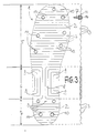
- FIG. 7 shows an insert 1 which has a transverse profile 2 in the forefoot area, but a continuous longitudinal profile 8 in the joint and heel area and with a passage holes 10 is provided for direct attachment of spikes or for attachment of fasteners for spikes.
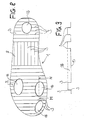
- FIG. 8 shows a plan view of a further embodiment of an insert 1 according to the invention, the transverse profile 2 of which, which is provided in the forefoot area and in the heel area between a longitudinal profile 8 in the joint area, is interrupted by a plurality of depressions 16 directed towards the floor.
- the depressions can be circular.
- the three depressions 16 provided in the forefoot area are located in the area of the big toe and the ball of the foot, while the rear depression 16 is located in the area of the heel.
- depressions 16 serve for better transmission of the foot pressure to the floor.
- FIG. 9 which shows a section along line M-N of FIG. 8 through one of the depressions, illustrates, the bottom 17 of the depression 16 is flat or at the deepest profiling level, that is to say it is closest to the floor.
- FIG. 10 shows a sole 18 with an insert 1 shown in broken lines, which extends only over the forefoot area and is provided with a transverse profile 2 throughout.
- FIG. 11 shows only the outsole of the sole 18 in the longitudinal section of FIG. 11 along the line ST through the sole of FIG. 10, only the outsole of the sole 18 is shown, while the plastic material in which the insert 1 is foamed and which is firmly connected to the outsole is omitted for the sake of illustration .
- FIGS. 12 and 13 show schematically how an insert 1 is preferably integrated into the overall structure of a sole, namely between the outsole 19 on the one hand and the insole 20 and the footbed 21 and the other on the other hand, the heel part 22 can be a wedge insert in the case of the flat sole 18 of FIG.
- Both the insert 1 of the sole 18 according to FIG. 12 and that of the sole according to FIG. 13 has a continuous transverse profile in the forefoot area and in the heel area, while a longitudinal profile 8 is provided in the joint area.
- this longitudinal profiling is designed to rise in an arc shape, as can be seen at 23, and it passes over a steeply sloping region 24 of the insert 1 at the beginning of the heel into the transverse profiling 2 of the heel region.
- spikes 12 are inserted into the transverse profiling 2 of the forefoot area and the heel area through corresponding through holes of the insert 1 and, at their foot parts 25, which are supported laterally on the vertical flanks of the transverse profiling 2, are welded or inlaid with the insert 1, for example otherwise attached to this insert.
- all customary materials can be used, wherein other customary inserts, such as the heel wedge in the wedge shoe according to FIG. 12, can be foamed into the sole together with the insert 1.
- FIG. 14 shows a partial cross section through an insert according to the invention, which consists of a composite panel material that is composed of several layers 26, 27 and 28, which are bonded to form an integral composite material:
- the bottom layer 28 in FIG. 14 consists of side by side the lying square box profiles 29, which are arranged at a very small distance U of, for example, 0.1 mm or less from one another or also closely next to one another. These box profiles 29 are firmly connected by means of the layer 27 made of adhesive to the layer 26 consisting of a resiliently flexible, flat plate material.
- insert 1 can only bend in the direction of arrow X upwards, but not in the opposite direction, since in the latter case the side parts 30 of adjacent box profiles 29 are supported against one another.
- a shoe, the sole of which is provided with such an insert is particularly suitable, for example, as a soccer shoe, since this insert prevents the sole from being bent down undesirably when the ball is kicked, for example when shooting at the goal.
- the plate material which forms the layer 26 can, for example, consist of spring steel or Teflon and have a thickness V, depending on the type of material, between preferably 0.1 mm and 2 mm, while the box profiles 29, which can be extruded from a high-strength aluminum alloy, for example , A side length W in the range of preferably 3 mm to 5 mm.
- the box profiles 29 or any other profiles that are provided in such a composite sheet material, if they are made of metal, can be provided with a soft plastic coating, which largely dampens the noise that occurs when the profiles collide.
- insole 31 which comprises an insert 1 with transverse profiling 2 and a filling compound 33 (shown hatched) which fills the profiling cavities or interspaces 32.
- This filler 33 fills the profiling cavities 32 so that the upper surface 34 and the lower surface 35 of the insole are flat.
- the insert 1 and the filling compound 33 are preferably firmly bonded to one another, for example by gluing or vulcanization, the insert, if it is made of metal, preferably being primed to improve adhesion.
- the filling compound can be or contain plastic and / or felt and / or other filling material.
- the thickness of the insole 31 is equal to the height H of the insert 1
- the thickness R of the filling compound 33 is greater than the height H of the insert 1, so that thin layers are provided on both sides of the insole Layers Y and Z of filling compound are present over the insert 1.
- the layer Y can also be provided only on one side, preferably on the side facing the foot, in particular to improve comfort for the foot.
- the insert 1 in FIG. 15, which has a trapezoidal cross-section 2 rounded in cross section, can be, for example, the insert shown in FIG. 1, in which, for example, the insert made of primed spring steel sheet is preferably 0.2 mm Material thickness with a profile period P of 5 mm and a height H of 2.0 mm and is made flat on both sides with a filling compound made of flexible plastic.
- the insert 1 in FIG. 16, which has a groove-shaped transverse profile, can be the insert shown in FIG. 2, for example.
- the insert 1 in FIG. 17, which has a zigzag-shaped transverse profile, can be, for example, the insert shown in FIG. 3, but preferably without the stud holes 10 and without the flat areas 13 of FIG. 3.
- the insole 31 can be made of
- Each insert according to the invention can be produced, and in the case of the insert according to FIGS. 8 and 9, the depressions 16 can also be filled with the filling compound 33, which can also have shock-absorbing properties.
- the filling compound has a substantially lower hardness than the material of the insert, for example it is soft-elastic and possibly also shock absorbing, so that the properties of the insert according to the invention are highly effective despite the filling compound.
- the plastic material with which an insert according to the invention can be formed is soft-elastic and possibly also shock absorbing.
Landscapes
- Health & Medical Sciences (AREA)
- General Health & Medical Sciences (AREA)
- Epidemiology (AREA)
- Public Health (AREA)
- Physical Education & Sports Medicine (AREA)
- Chemical & Material Sciences (AREA)
- Engineering & Computer Science (AREA)
- Materials Engineering (AREA)
- Footwear And Its Accessory, Manufacturing Method And Apparatuses (AREA)
- Organic Low-Molecular-Weight Compounds And Preparation Thereof (AREA)
Priority Applications (1)
| Application Number | Priority Date | Filing Date | Title |
|---|---|---|---|
| AT89120182T ATE83898T1 (de) | 1988-12-13 | 1989-10-31 | Einlage fuer einen schuh. |
Applications Claiming Priority (8)
| Application Number | Priority Date | Filing Date | Title |
|---|---|---|---|
| DE8815448U DE8815448U1 (de) | 1988-12-13 | 1988-12-13 | Golfschuh |
| DE8815448U | 1988-12-13 | ||
| DE8904336U DE8904336U1 (de) | 1989-04-07 | 1989-04-07 | Golfschuh |
| DE8904336U | 1989-04-07 | ||
| DE8905979U | 1989-05-12 | ||
| DE8905979U DE8905979U1 (de) | 1989-05-12 | 1989-05-12 | Sportschuh, insbesondere Golfschuh |
| EP89119833 | 1989-10-25 | ||
| EP89119833A EP0373330A1 (fr) | 1988-12-13 | 1989-10-25 | Pièce d'insertion pour chaussure |
Publications (2)
| Publication Number | Publication Date |
|---|---|
| EP0373336A1 true EP0373336A1 (fr) | 1990-06-20 |
| EP0373336B1 EP0373336B1 (fr) | 1992-12-30 |
Family
ID=27436346
Family Applications (1)
| Application Number | Title | Priority Date | Filing Date |
|---|---|---|---|
| EP89120182A Expired - Lifetime EP0373336B1 (fr) | 1988-12-13 | 1989-10-31 | Pièce d'insertion pour chaussure |
Country Status (13)
| Country | Link |
|---|---|
| US (1) | US5720118A (fr) |
| EP (1) | EP0373336B1 (fr) |
| JP (1) | JP2930118B2 (fr) |
| AT (1) | ATE83898T1 (fr) |
| AU (1) | AU624881B2 (fr) |
| BR (1) | BR8906360A (fr) |
| CA (1) | CA2003132A1 (fr) |
| DE (1) | DE58903176D1 (fr) |
| ES (1) | ES2037372T3 (fr) |
| HK (1) | HK25996A (fr) |
| HU (1) | HU215998B (fr) |
| PT (1) | PT92528B (fr) |
| RU (1) | RU1837821C (fr) |
Cited By (12)
| Publication number | Priority date | Publication date | Assignee | Title |
|---|---|---|---|---|
| DE4137350A1 (de) * | 1991-11-13 | 1993-05-19 | Esjot Werk Schiermeister U Jun | Mehrschichtige schuhsohle, insbesondere fuer sportschuhe |
| FR2697141A1 (fr) * | 1992-10-27 | 1994-04-29 | Rossignol Sa | Chaussure de ski de fond perfectionnée. |
| WO1995027416A1 (fr) * | 1994-04-12 | 1995-10-19 | Nordica S.P.A. | Semelle renforcee destinee notamment a des chaussures de sport |
| WO1996004811A1 (fr) * | 1994-08-12 | 1996-02-22 | One Sport, Inc. | Chaussure |
| WO1997046125A3 (fr) * | 1996-05-30 | 1998-03-26 | Helmut Mayer | Chaussure, son procede de production et son utilisation |
| US6557270B2 (en) | 2000-05-09 | 2003-05-06 | Mizuno Corporation | Sole design and structure for athletic shoe |
| USRE40474E1 (en) | 1991-12-24 | 2008-09-02 | Salomon S.A. | Multilayer sole for sport shoes |
| WO2013017277A1 (fr) * | 2011-08-03 | 2013-02-07 | Mayer Gbr | Châssis de semelle pour chaussures |
| DE202013003797U1 (de) | 2013-04-23 | 2013-05-27 | Fleximed Ag | Einlegesohle |
| WO2013167155A1 (fr) * | 2012-05-09 | 2013-11-14 | Norbert Schmid Gmbh & Co. Kg | Semelle intérieure pour chaussures |
| DE102013006962A1 (de) | 2013-04-23 | 2014-10-23 | Fleximed Ag | Einlegesohle |
| EP2684475B1 (fr) * | 2012-07-09 | 2018-02-14 | Stuppy Schuhfabrik GmbH | Semelle pour chaussure de sécurité pour diabétiques ainsi que chaussure de sécurité pour diabétiques équipée d'une telle semelle |
Families Citing this family (81)
| Publication number | Priority date | Publication date | Assignee | Title |
|---|---|---|---|---|
| JPH03273845A (ja) | 1990-01-17 | 1991-12-05 | Siegel:Kk | ステッピングモータにおける吸振構造 |
| JP2000502575A (ja) * | 1995-12-22 | 2000-03-07 | ヘキスト・セラニーズ・コーポレーション | 三次元の成形繊維生成物を含む靴 |
| IT1290354B1 (it) * | 1997-02-07 | 1998-10-22 | Vibram Spa | Suola biomeccanica |
| US6314664B1 (en) | 1997-04-18 | 2001-11-13 | Mizuno Corporation | Athletic shoe midsole design and construction |
| JPH119757A (ja) * | 1997-06-20 | 1999-01-19 | Fuji Heavy Ind Ltd | 滑走板 |
| FR2777429B1 (fr) | 1998-04-21 | 2000-05-26 | Salomon Sa | Chaussure a semelage avec structure deformable |
| JP3215664B2 (ja) * | 1998-05-22 | 2001-10-09 | 美津濃株式会社 | スポーツ用シューズのミッドソール構造 |
| JP3238129B2 (ja) | 1998-06-08 | 2001-12-10 | 美津濃株式会社 | スポーツ用シューズのミッドソール構造 |
| JP3207805B2 (ja) * | 1998-06-25 | 2001-09-10 | 美津濃株式会社 | スポーツ用シューズのミッドソール構造 |
| US6023861A (en) * | 1998-08-17 | 2000-02-15 | Calzaturificio S.C.A.A.P.A. Spa | Arch support for a sports shoe |
| JP3238132B2 (ja) | 1998-10-02 | 2001-12-10 | 美津濃株式会社 | スポーツ用シューズのミッドソール構造 |
| SG126668A1 (en) * | 1998-12-29 | 2006-11-29 | Bfr Holding Ltd | Protective boot and sole structure |
| DE19904744B4 (de) | 1999-02-05 | 2005-11-10 | Adidas International Marketing B.V. | Schuh |
| JP2000296001A (ja) * | 1999-04-16 | 2000-10-24 | Mizuno Corp | スポーツ用シューズのソール構造 |
| JP2001008704A (ja) | 1999-07-02 | 2001-01-16 | Mizuno Corp | スポーツ用シューズのミッドソール構造 |
| JP4906153B2 (ja) | 2001-06-28 | 2012-03-28 | 美津濃株式会社 | スポーツ用シューズのミッドソール構造 |
| JP3947658B2 (ja) | 2001-06-28 | 2007-07-25 | 美津濃株式会社 | スポーツ用シューズのミッドソール構造 |
| EP1354526A1 (fr) * | 2002-04-18 | 2003-10-22 | Astra S.r.l. | Insert en métal pour chaussures de travail et de securité |
| US7487604B2 (en) * | 2002-09-11 | 2009-02-10 | Perron Jr J Edward | Soccer shoe component or insert made of one material and/or a composite and/or laminate of one or more materials for enhancing the performance of the soccer shoe |
| US8191285B2 (en) | 2003-09-11 | 2012-06-05 | Perron Jr J Edward | Soccer shoe component or insert made of one material and/or a composite and/or laminate of one or more materials for enhancing the performance of the soccer shoe |
| US20050160630A1 (en) * | 2002-09-11 | 2005-07-28 | Perron J. E.Jr. | Soccer shoe component or insert made of one material and/or a composite and/or laminate of one or more materials for enhancing the performance of the soccer shoe |
| FR2848389B1 (fr) * | 2002-12-11 | 2006-02-10 | Salomon Sa | Semelage de chaussure |
| US7013581B2 (en) * | 2003-06-11 | 2006-03-21 | Nike, Inc. | Article of footwear having a suspended footbed |
| CN100528023C (zh) * | 2003-07-17 | 2009-08-19 | 红翼鞋业公司 | 鞋子的一体式龙骨结构 |
| WO2005096733A2 (fr) * | 2003-09-11 | 2005-10-20 | Perron Edward J Jr | Composant ou insert de chaussure de foot fait d'un materiau et/ou d'un materiau composite et/ou lamine fait d'un ou de plusieurs materiaux destines a ameliorer l'efficacite de la chaussure de foot |
| US7386945B2 (en) * | 2003-10-30 | 2008-06-17 | Reebok International Ltd. | Sole for increased circulation |
| DE112005001639A5 (de) * | 2004-05-08 | 2007-05-31 | Becker, Norbert L., Dr.med. | Verfahren zur zerstörungsfreien Ermittlung der Innenmasse und/oder Aussenmasse eines Schuhs und/oder der Aussenmasse eines Leistens |
| DE102004049369A1 (de) * | 2004-10-09 | 2006-04-20 | Caprice Schuhproduktion Gmbh & Co. Kg | Schuhsohle |
| US8549774B2 (en) * | 2005-11-15 | 2013-10-08 | Nike, Inc. | Flexible shank for an article of footwear |
| JP4851781B2 (ja) * | 2005-11-17 | 2012-01-11 | 株式会社アシックス | 横振れ抑制機能を備えた靴 |
| GB2432294A (en) * | 2005-11-18 | 2007-05-23 | Clifton Bradeley | Insert for cycling shoe |
| DE102006015649B4 (de) * | 2006-04-04 | 2008-02-28 | Adidas International Marketing B.V. | Schuh |
| US7685740B2 (en) * | 2006-07-13 | 2010-03-30 | Nike, Inc. | Dance shoe |
| US7954261B2 (en) * | 2006-09-27 | 2011-06-07 | Rush University Medical Center | Joint load reducing footwear |
| ITPD20060372A1 (it) * | 2006-10-06 | 2008-04-07 | Novation S P A | Soletta per calzature a struttura rinforzata |
| JP4764396B2 (ja) * | 2007-09-26 | 2011-08-31 | 美津濃株式会社 | スポーツ用シューズのソール構造 |
| JP5044529B2 (ja) * | 2008-11-13 | 2012-10-10 | アクシュネット カンパニー | ゴルフシューズ |
| DE102008059030B4 (de) * | 2008-11-26 | 2014-09-25 | Helmut Mayer Gbr Mbh | Einlegesohle |
| US20100212187A1 (en) * | 2009-02-20 | 2010-08-26 | Implus Footcare, Llc | Shoe insole element |
| US20120023776A1 (en) * | 2009-03-09 | 2012-02-02 | Aetrex Worldwide, Inc. | Shoe sole inserts for pressure distribution |
| CN102438478B (zh) * | 2009-03-23 | 2015-04-29 | 新平衡运动鞋公司 | 用于增加不稳定性的鞋底 |
| USD634524S1 (en) | 2009-10-23 | 2011-03-22 | New Balance Athletic Shoe, Inc. | Shoe |
| KR20120132692A (ko) * | 2010-03-31 | 2012-12-07 | 엑스오아틀레틱스, 엘엘씨 | 보호 패드를 형성하는 시스템 및 방법 |
| US9055784B2 (en) * | 2011-01-06 | 2015-06-16 | Nike, Inc. | Article of footwear having a sole structure incorporating a plate and chamber |
| US20120260527A1 (en) * | 2011-04-15 | 2012-10-18 | Ls Networks Corporated Limited | shoe having triple-hardness midsole, outsole, and upper with support for preventing an overpronation |
| ITRM20120251A1 (it) * | 2012-05-31 | 2013-12-01 | Itop S P A Officine Ortopediche | Ortesi. |
| US9615621B2 (en) * | 2012-06-04 | 2017-04-11 | Nike, Inc. | Sole structure with integrated cleat member and methods of making |
| FR2993758B1 (fr) * | 2012-07-27 | 2015-03-27 | Salomon Sas | Chaussure a semelage ameliore |
| US9427044B2 (en) | 2012-09-21 | 2016-08-30 | Nike, Inc. | Reinforcing member for article of footwear |
| US10010137B2 (en) | 2014-07-30 | 2018-07-03 | Nike, Inc. | Article of footwear with banking midsole with embedded resilient plate |
| JP2018501916A (ja) * | 2015-01-19 | 2018-01-25 | ザ・ロックポート・カンパニー・エルエルシー | 履物底 |
| DE202015102695U1 (de) | 2015-05-26 | 2016-08-29 | Willi Mander Gmbh | Einlegesohle |
| US10834990B2 (en) * | 2015-05-26 | 2020-11-17 | Nike, Inc. | Foot support members that provide dynamically transformative properties |
| CN104872924A (zh) * | 2015-05-27 | 2015-09-02 | 佛山市南方鞋材有限公司 | 一种耐弯折的鞋大底 |
| MX392120B (es) | 2015-10-02 | 2025-03-21 | Nike Innovate Cv | Placa para calzado. |
| US10448704B2 (en) | 2015-10-02 | 2019-10-22 | Nike, Inc. | Plate with foam for footwear |
| WO2017079249A1 (fr) * | 2015-11-05 | 2017-05-11 | Nike Innovate C.V. | Structure de semelle pour article de chaussures ayant une rigidité de flexion non linéaire dotée de rainures de compression et nervures descendantes |
| US10856610B2 (en) | 2016-01-15 | 2020-12-08 | Hoe-Phuan Ng | Manual and dynamic shoe comfortness adjustment methods |
| US11197514B2 (en) | 2016-02-29 | 2021-12-14 | Nike, Inc. | Layered sole structure for an article of footwear |
| CN112971269B (zh) | 2016-07-20 | 2022-12-16 | 耐克创新有限合伙公司 | 用于鞋类制品或装备的复合板 |
| CN113261746B (zh) | 2016-07-20 | 2023-02-17 | 耐克创新有限合伙公司 | 鞋板 |
| US10231514B2 (en) | 2017-02-02 | 2019-03-19 | Adidas Ag | Sole board |
| DE102017001266A1 (de) | 2017-02-10 | 2018-08-16 | Oliver Horsky | Einlegesohle für Schuhe aller Art zum Schutz vor Kälte, Nässe und Druckstellen |
| US11051586B2 (en) | 2017-05-11 | 2021-07-06 | OrthoGolfer, LLC | Insole and footbed for golf shoes that improves balance, posture and stability to enhance the golf swing |
| CN113876073A (zh) * | 2017-05-23 | 2022-01-04 | 耐克创新有限合伙公司 | 具有波状鞋底板的用于鞋类物品的鞋底结构 |
| CN115474732B (zh) | 2017-08-31 | 2026-02-06 | 耐克创新有限合伙公司 | 鞋类物品的鞋底结构和相关方法 |
| WO2019046432A1 (fr) | 2017-08-31 | 2019-03-07 | Nike Innovate C.V. | Structure de semelle d'un article chaussant et procédés associés |
| US11344078B2 (en) | 2018-04-16 | 2022-05-31 | Nike, Inc. | Outsole plate |
| WO2019204202A1 (fr) | 2018-04-16 | 2019-10-24 | Nike Innovate C.V. | Plaque de semelle d'usure |
| WO2019231594A1 (fr) | 2018-05-31 | 2019-12-05 | Nike Innovate C.V. | Plaque de semelle de chaussure à ondes non parallèles d'épaisseur variable |
| US11006695B2 (en) | 2018-05-31 | 2021-05-18 | Nike, Inc. | Footwear sole plate with forefoot through hole |
| US11930882B2 (en) | 2018-08-08 | 2024-03-19 | Nike, Inc. | Midsole structure of an article of footwear including mesh |
| MX2021013319A (es) * | 2019-05-08 | 2021-11-17 | Scholl´S Wellness Company Llc | Soporte de arco flexible para calzado. |
| US20220279895A1 (en) * | 2019-08-26 | 2022-09-08 | Hewlett-Packard Development Company, L.P. | Footwear midsoles with baffles |
| US11490679B2 (en) | 2019-09-25 | 2022-11-08 | Nike, Inc. | Foot support components for articles of footwear |
| DE102020202237B4 (de) * | 2020-02-21 | 2023-05-17 | Adidas Ag | Sohle umfassend individuell auslenkbare Verstärkungselemente, und Schuh mit einer solchen Sohle |
| US11641906B2 (en) | 2020-02-27 | 2023-05-09 | Nike, Inc. | Medially-located lateral footwear stabilizer |
| WO2021202318A1 (fr) | 2020-03-29 | 2021-10-07 | Nike Innovate C.V. | Structure de semelle destinée à un article de chaussure |
| TWI807436B (zh) * | 2021-09-30 | 2023-07-01 | 復盛應用科技股份有限公司 | 鞋底墊片 |
| US12471662B2 (en) * | 2022-04-14 | 2025-11-18 | Bass Pro Intellectual Property, L.L.C. | Footwear with cork outsole |
| WO2026010655A1 (fr) * | 2024-07-02 | 2026-01-08 | Robinson Pauline Patricia | Systèmes de chaussure renforcés |
Citations (9)
| Publication number | Priority date | Publication date | Assignee | Title |
|---|---|---|---|---|
| US2304936A (en) * | 1940-08-28 | 1942-12-15 | B F Mcdonald Company | Protective armor |
| FR1236470A (fr) * | 1959-09-25 | 1960-07-15 | Producteurs Europ Soc D | Semelle de chaussure comportant un dispositif de protection contre les perforations |
| GB1257524A (fr) * | 1969-02-12 | 1971-12-22 | ||
| DE2645007A1 (de) * | 1976-03-27 | 1978-04-13 | Continental Gummi Werke Ag | Skistiefel |
| US4186500A (en) * | 1978-04-27 | 1980-02-05 | Tyrol Shoe Co. Ltd. | Molded cross-country ski boot |
| FR2457081A1 (fr) * | 1979-05-21 | 1980-12-19 | Salomon & Fils F | Chaussure de sport et plus particulierement de ski de fond |
| US4439937A (en) * | 1982-07-26 | 1984-04-03 | Daswick Alexander C | Integrally cast shoe sole containing stiffener member |
| FR2556569A1 (fr) * | 1983-12-14 | 1985-06-21 | Salomon & Fils F | Semelle de chaussure de sport, notamment pour le ski de fond |
| US4674202A (en) * | 1983-12-16 | 1987-06-23 | Warrington Inc. | Cross-country ski boot |
Family Cites Families (14)
| Publication number | Priority date | Publication date | Assignee | Title |
|---|---|---|---|---|
| US1308395A (en) * | 1919-07-01 | Jesse a | ||
| US1704187A (en) * | 1927-07-22 | 1929-03-05 | Hood Rubber Co Inc | Sole for boots and shoes |
| US2124819A (en) * | 1937-08-23 | 1938-07-26 | Henry G Halloran | Shoe bottom filler |
| US2258734A (en) * | 1939-06-22 | 1941-10-14 | David R Brady | Peg for athletic shoes |
| US3444630A (en) * | 1967-10-13 | 1969-05-20 | Dominick J Morelli | Football shoe cleat and arch construction |
| US3492744A (en) * | 1968-05-09 | 1970-02-03 | Wright & Co Inc E T | Golf shoe and bottom therefor |
| GB2060350A (en) * | 1979-07-19 | 1981-05-07 | Orme Polymer Eng Ltd | Safety footwear |
| DE3027601C2 (de) * | 1980-07-21 | 1982-06-24 | Herbert Dr.-Ing. 8032 Lochham Funck | Formsohle mit durchtrittssicherer Einlage |
| JPS59103605U (ja) * | 1982-12-28 | 1984-07-12 | 美津濃株式会社 | 運動靴の靴底 |
| US4484398A (en) * | 1983-07-21 | 1984-11-27 | Goodwin Boyd G | Spiked shoe protector |
| DE3579364D1 (de) * | 1984-05-30 | 1990-10-04 | Indentor Ag | Mittel zur speicherung und verteilung von waerme. |
| GB2245813B (en) * | 1990-07-09 | 1994-08-24 | Dancing Bonzai Co | Ballet shoe |
| CA2022130C (fr) * | 1990-07-27 | 1997-02-25 | Albertus A. W. Aleven | Semelle de chaussure de securite resistante a la perforation |
| US5179791A (en) * | 1991-08-19 | 1993-01-19 | Lain Cheng K | Torsional spring insole and method |
-
1989
- 1989-10-31 DE DE8989120182T patent/DE58903176D1/de not_active Expired - Fee Related
- 1989-10-31 EP EP89120182A patent/EP0373336B1/fr not_active Expired - Lifetime
- 1989-10-31 AT AT89120182T patent/ATE83898T1/de not_active IP Right Cessation
- 1989-10-31 ES ES198989120182T patent/ES2037372T3/es not_active Expired - Lifetime
- 1989-11-16 CA CA002003132A patent/CA2003132A1/fr not_active Abandoned
- 1989-12-05 HU HU6430/89A patent/HU215998B/hu not_active IP Right Cessation
- 1989-12-06 AU AU45901/89A patent/AU624881B2/en not_active Ceased
- 1989-12-07 PT PT92528A patent/PT92528B/pt not_active IP Right Cessation
- 1989-12-07 JP JP1320395A patent/JP2930118B2/ja not_active Expired - Fee Related
- 1989-12-08 BR BR898906360A patent/BR8906360A/pt not_active Application Discontinuation
- 1989-12-11 RU SU894742622A patent/RU1837821C/ru active
-
1996
- 1996-02-08 HK HK25996A patent/HK25996A/xx not_active IP Right Cessation
-
1997
- 1997-03-28 US US08/829,476 patent/US5720118A/en not_active Expired - Fee Related
Patent Citations (9)
| Publication number | Priority date | Publication date | Assignee | Title |
|---|---|---|---|---|
| US2304936A (en) * | 1940-08-28 | 1942-12-15 | B F Mcdonald Company | Protective armor |
| FR1236470A (fr) * | 1959-09-25 | 1960-07-15 | Producteurs Europ Soc D | Semelle de chaussure comportant un dispositif de protection contre les perforations |
| GB1257524A (fr) * | 1969-02-12 | 1971-12-22 | ||
| DE2645007A1 (de) * | 1976-03-27 | 1978-04-13 | Continental Gummi Werke Ag | Skistiefel |
| US4186500A (en) * | 1978-04-27 | 1980-02-05 | Tyrol Shoe Co. Ltd. | Molded cross-country ski boot |
| FR2457081A1 (fr) * | 1979-05-21 | 1980-12-19 | Salomon & Fils F | Chaussure de sport et plus particulierement de ski de fond |
| US4439937A (en) * | 1982-07-26 | 1984-04-03 | Daswick Alexander C | Integrally cast shoe sole containing stiffener member |
| FR2556569A1 (fr) * | 1983-12-14 | 1985-06-21 | Salomon & Fils F | Semelle de chaussure de sport, notamment pour le ski de fond |
| US4674202A (en) * | 1983-12-16 | 1987-06-23 | Warrington Inc. | Cross-country ski boot |
Cited By (16)
| Publication number | Priority date | Publication date | Assignee | Title |
|---|---|---|---|---|
| DE4137350A1 (de) * | 1991-11-13 | 1993-05-19 | Esjot Werk Schiermeister U Jun | Mehrschichtige schuhsohle, insbesondere fuer sportschuhe |
| USRE40474E1 (en) | 1991-12-24 | 2008-09-02 | Salomon S.A. | Multilayer sole for sport shoes |
| FR2697141A1 (fr) * | 1992-10-27 | 1994-04-29 | Rossignol Sa | Chaussure de ski de fond perfectionnée. |
| EP0595732A1 (fr) * | 1992-10-27 | 1994-05-04 | Skis Rossignol S.A. | Chaussure de ski de fond à semelle renforcée |
| WO1995027416A1 (fr) * | 1994-04-12 | 1995-10-19 | Nordica S.P.A. | Semelle renforcee destinee notamment a des chaussures de sport |
| WO1996004811A1 (fr) * | 1994-08-12 | 1996-02-22 | One Sport, Inc. | Chaussure |
| WO1997046125A3 (fr) * | 1996-05-30 | 1998-03-26 | Helmut Mayer | Chaussure, son procede de production et son utilisation |
| US6810605B2 (en) | 2000-05-09 | 2004-11-02 | Mizuno Corporation | Sole design and structure for athletic shoe |
| US6807752B2 (en) | 2000-05-09 | 2004-10-26 | Mizuno Corporation | Sole design and structure for athletic shoe |
| US6557270B2 (en) | 2000-05-09 | 2003-05-06 | Mizuno Corporation | Sole design and structure for athletic shoe |
| WO2013017277A1 (fr) * | 2011-08-03 | 2013-02-07 | Mayer Gbr | Châssis de semelle pour chaussures |
| WO2013167155A1 (fr) * | 2012-05-09 | 2013-11-14 | Norbert Schmid Gmbh & Co. Kg | Semelle intérieure pour chaussures |
| EP2684475B1 (fr) * | 2012-07-09 | 2018-02-14 | Stuppy Schuhfabrik GmbH | Semelle pour chaussure de sécurité pour diabétiques ainsi que chaussure de sécurité pour diabétiques équipée d'une telle semelle |
| DE202013003797U1 (de) | 2013-04-23 | 2013-05-27 | Fleximed Ag | Einlegesohle |
| DE102013006962A1 (de) | 2013-04-23 | 2014-10-23 | Fleximed Ag | Einlegesohle |
| WO2014174367A1 (fr) | 2013-04-23 | 2014-10-30 | Fleximed Ag | Semelle intérieure |
Also Published As
| Publication number | Publication date |
|---|---|
| HUT65698A (en) | 1994-07-28 |
| BR8906360A (pt) | 1990-08-21 |
| RU1837821C (ru) | 1993-08-30 |
| JPH02264602A (ja) | 1990-10-29 |
| PT92528A (pt) | 1990-06-29 |
| US5720118A (en) | 1998-02-24 |
| HK25996A (en) | 1996-02-16 |
| JP2930118B2 (ja) | 1999-08-03 |
| CA2003132A1 (fr) | 1990-06-13 |
| PT92528B (pt) | 1997-05-28 |
| ATE83898T1 (de) | 1993-01-15 |
| AU624881B2 (en) | 1992-06-25 |
| ES2037372T3 (es) | 1993-06-16 |
| HU896430D0 (en) | 1990-02-28 |
| AU4590189A (en) | 1990-06-21 |
| HU215998B (hu) | 1999-04-28 |
| DE58903176D1 (de) | 1993-02-11 |
| EP0373336B1 (fr) | 1992-12-30 |
Similar Documents
| Publication | Publication Date | Title |
|---|---|---|
| EP0373336B1 (fr) | Pièce d'insertion pour chaussure | |
| DE69908056T2 (de) | Schuh mit verformbarer besohlung | |
| DE69008385T2 (de) | Sohle mit elastische Kugeln enthaltendem Hohlraum für Schuhwerk zum Massieren des Fusses. | |
| DE69224050T2 (de) | Mehrschichtige Sportschuhsohle | |
| DE60030188T2 (de) | Schuhwerk | |
| DE112005002327B4 (de) | Stoßabsorbierende Vorrichtung für eine Schuhsohle in einem Rückfußteil | |
| EP0087104B1 (fr) | Chaussure de sport avec semelle d'usure élastique en matière plastique | |
| DE68902415T3 (de) | Schuhsohle für sportliche Aktivitäten, auch im Freien. | |
| DE69809474T2 (de) | Sohle mit grosser Rutschsicherheit | |
| DE19950121C1 (de) | Sohle | |
| DE102011102849B4 (de) | Schuhsole mit Röhren | |
| EP0185781B1 (fr) | Semelle de chaussure en matière plastique ou en caoutchouc | |
| DE102010040964B4 (de) | Stollen für Stollenschuh | |
| EP0373330A1 (fr) | Pièce d'insertion pour chaussure | |
| EP2547226B1 (fr) | Semelle pour chaussure et chaussure | |
| DE3715451A1 (de) | Golfschuh | |
| DE3318121A1 (de) | Schuhsohle | |
| DE3120349A1 (de) | Golfschuhe | |
| AT16785U1 (de) | Schuh | |
| DE69123303T2 (de) | Sohle für Schuhwerk | |
| EP0458174A1 (fr) | Article chaussure avec semelle constituée au moins de deux couches | |
| EP0434076A2 (fr) | Insert pour une chaussure | |
| DE19641866A1 (de) | Schuh und Verfahren zu dessen Herstellung sowie Verwendung desselben | |
| WO2022161785A1 (fr) | Semelle à propriétés d'amortissement variables | |
| CH718291A2 (de) | Sohle mit horizontaler und vertikaler Dämpfung. |
Legal Events
| Date | Code | Title | Description |
|---|---|---|---|
| PUAI | Public reference made under article 153(3) epc to a published international application that has entered the european phase |
Free format text: ORIGINAL CODE: 0009012 |
|
| AK | Designated contracting states |
Kind code of ref document: A1 Designated state(s): AT BE CH DE ES FR GB GR IT LI LU NL SE |
|
| 17P | Request for examination filed |
Effective date: 19901123 |
|
| 17Q | First examination report despatched |
Effective date: 19910618 |
|
| GRAA | (expected) grant |
Free format text: ORIGINAL CODE: 0009210 |
|
| AK | Designated contracting states |
Kind code of ref document: B1 Designated state(s): AT BE CH DE ES FR GB GR IT LI LU NL SE |
|
| REF | Corresponds to: |
Ref document number: 83898 Country of ref document: AT Date of ref document: 19930115 Kind code of ref document: T |
|
| ITF | It: translation for a ep patent filed | ||
| REF | Corresponds to: |
Ref document number: 58903176 Country of ref document: DE Date of ref document: 19930211 |
|
| GBT | Gb: translation of ep patent filed (gb section 77(6)(a)/1977) |
Effective date: 19930211 |
|
| ET | Fr: translation filed | ||
| REG | Reference to a national code |
Ref country code: GR Ref legal event code: FG4A Free format text: 3006720 |
|
| REG | Reference to a national code |
Ref country code: ES Ref legal event code: FG2A Ref document number: 2037372 Country of ref document: ES Kind code of ref document: T3 |
|
| PLBI | Opposition filed |
Free format text: ORIGINAL CODE: 0009260 |
|
| PGFP | Annual fee paid to national office [announced via postgrant information from national office to epo] |
Ref country code: LU Payment date: 19931015 Year of fee payment: 5 |
|
| 26 | Opposition filed |
Opponent name: SCHUHFABRIKEN OTTERBECK GMBH & CO. Effective date: 19930930 |
|
| EPTA | Lu: last paid annual fee | ||
| NLR1 | Nl: opposition has been filed with the epo |
Opponent name: SCHUHFABRIKEN OTTERBECK GMB& CO. |
|
| PG25 | Lapsed in a contracting state [announced via postgrant information from national office to epo] |
Ref country code: LU Free format text: LAPSE BECAUSE OF NON-PAYMENT OF DUE FEES Effective date: 19941031 |
|
| PLBM | Termination of opposition procedure: date of legal effect published |
Free format text: ORIGINAL CODE: 0009276 |
|
| PLAD | Information related to termination of opposition procedure modified |
Free format text: ORIGINAL CODE: 0009299OPPC |
|
| EAL | Se: european patent in force in sweden |
Ref document number: 89120182.4 |
|
| 27C | Opposition proceedings terminated |
Effective date: 19941020 |
|
| PLAD | Information related to termination of opposition procedure modified |
Free format text: ORIGINAL CODE: 0009299OPPC |
|
| STAA | Information on the status of an ep patent application or granted ep patent |
Free format text: STATUS: OPPOSITION PROCEDURE CLOSED |
|
| D27C | Opposition proceedings terminated (deleted) | ||
| R27C | Opposition proceedings terminated (corrected) |
Effective date: 19941020 |
|
| REG | Reference to a national code |
Ref country code: GB Ref legal event code: IF02 |
|
| PGFP | Annual fee paid to national office [announced via postgrant information from national office to epo] |
Ref country code: GR Payment date: 20060914 Year of fee payment: 18 |
|
| PGFP | Annual fee paid to national office [announced via postgrant information from national office to epo] |
Ref country code: NL Payment date: 20071023 Year of fee payment: 19 Ref country code: ES Payment date: 20071106 Year of fee payment: 19 Ref country code: DE Payment date: 20071025 Year of fee payment: 19 |
|
| PGFP | Annual fee paid to national office [announced via postgrant information from national office to epo] |
Ref country code: AT Payment date: 20071026 Year of fee payment: 19 Ref country code: IT Payment date: 20071031 Year of fee payment: 19 Ref country code: CH Payment date: 20071029 Year of fee payment: 19 |
|
| PGFP | Annual fee paid to national office [announced via postgrant information from national office to epo] |
Ref country code: SE Payment date: 20071026 Year of fee payment: 19 Ref country code: BE Payment date: 20071213 Year of fee payment: 19 |
|
| PGFP | Annual fee paid to national office [announced via postgrant information from national office to epo] |
Ref country code: FR Payment date: 20071025 Year of fee payment: 19 Ref country code: GB Payment date: 20071031 Year of fee payment: 19 |
|
| BERE | Be: lapsed |
Owner name: *MAYER HELMUT Effective date: 20081031 |
|
| PG25 | Lapsed in a contracting state [announced via postgrant information from national office to epo] |
Ref country code: GR Free format text: LAPSE BECAUSE OF NON-PAYMENT OF DUE FEES Effective date: 20080505 |
|
| REG | Reference to a national code |
Ref country code: CH Ref legal event code: PL |
|
| GBPC | Gb: european patent ceased through non-payment of renewal fee |
Effective date: 20081031 |
|
| NLV4 | Nl: lapsed or anulled due to non-payment of the annual fee |
Effective date: 20090501 |
|
| EUG | Se: european patent has lapsed | ||
| REG | Reference to a national code |
Ref country code: FR Ref legal event code: ST Effective date: 20090630 |
|
| PG25 | Lapsed in a contracting state [announced via postgrant information from national office to epo] |
Ref country code: NL Free format text: LAPSE BECAUSE OF NON-PAYMENT OF DUE FEES Effective date: 20090501 |
|
| PG25 | Lapsed in a contracting state [announced via postgrant information from national office to epo] |
Ref country code: IT Free format text: LAPSE BECAUSE OF NON-PAYMENT OF DUE FEES Effective date: 20081031 Ref country code: AT Free format text: LAPSE BECAUSE OF NON-PAYMENT OF DUE FEES Effective date: 20081031 Ref country code: DE Free format text: LAPSE BECAUSE OF NON-PAYMENT OF DUE FEES Effective date: 20090501 |
|
| PG25 | Lapsed in a contracting state [announced via postgrant information from national office to epo] |
Ref country code: BE Free format text: LAPSE BECAUSE OF NON-PAYMENT OF DUE FEES Effective date: 20081031 |
|
| PG25 | Lapsed in a contracting state [announced via postgrant information from national office to epo] |
Ref country code: FR Free format text: LAPSE BECAUSE OF NON-PAYMENT OF DUE FEES Effective date: 20081031 Ref country code: CH Free format text: LAPSE BECAUSE OF NON-PAYMENT OF DUE FEES Effective date: 20081031 Ref country code: LI Free format text: LAPSE BECAUSE OF NON-PAYMENT OF DUE FEES Effective date: 20081031 |
|
| PLAB | Opposition data, opponent's data or that of the opponent's representative modified |
Free format text: ORIGINAL CODE: 0009299OPPO |
|
| PG25 | Lapsed in a contracting state [announced via postgrant information from national office to epo] |
Ref country code: GB Free format text: LAPSE BECAUSE OF NON-PAYMENT OF DUE FEES Effective date: 20081031 |
|
| REG | Reference to a national code |
Ref country code: ES Ref legal event code: FD2A Effective date: 20081103 |
|
| PG25 | Lapsed in a contracting state [announced via postgrant information from national office to epo] |
Ref country code: ES Free format text: LAPSE BECAUSE OF NON-PAYMENT OF DUE FEES Effective date: 20081103 |
|
| PG25 | Lapsed in a contracting state [announced via postgrant information from national office to epo] |
Ref country code: SE Free format text: LAPSE BECAUSE OF NON-PAYMENT OF DUE FEES Effective date: 20081101 |