EP0373355B1 - Système de détrompage - Google Patents
Système de détrompage Download PDFInfo
- Publication number
- EP0373355B1 EP0373355B1 EP89120597A EP89120597A EP0373355B1 EP 0373355 B1 EP0373355 B1 EP 0373355B1 EP 89120597 A EP89120597 A EP 89120597A EP 89120597 A EP89120597 A EP 89120597A EP 0373355 B1 EP0373355 B1 EP 0373355B1
- Authority
- EP
- European Patent Office
- Prior art keywords
- card
- cards
- tab
- cable
- grouper
- Prior art date
- Legal status (The legal status is an assumption and is not a legal conclusion. Google has not performed a legal analysis and makes no representation as to the accuracy of the status listed.)
- Expired - Lifetime
Links
- 241001417495 Serranidae Species 0.000 claims description 33
- 238000000034 method Methods 0.000 description 2
- 239000000853 adhesive Substances 0.000 description 1
- 230000001070 adhesive effect Effects 0.000 description 1
- 230000000712 assembly Effects 0.000 description 1
- 238000000429 assembly Methods 0.000 description 1
- 238000007796 conventional method Methods 0.000 description 1
- 230000004927 fusion Effects 0.000 description 1
- 238000003780 insertion Methods 0.000 description 1
- 230000037431 insertion Effects 0.000 description 1
- 230000003993 interaction Effects 0.000 description 1
- 230000013011 mating Effects 0.000 description 1
Images


Classifications
-
- H—ELECTRICITY
- H01—ELECTRIC ELEMENTS
- H01R—ELECTRICALLY-CONDUCTIVE CONNECTIONS; STRUCTURAL ASSOCIATIONS OF A PLURALITY OF MUTUALLY-INSULATED ELECTRICAL CONNECTING ELEMENTS; COUPLING DEVICES; CURRENT COLLECTORS
- H01R13/00—Details of coupling devices of the kinds covered by groups H01R12/70 or H01R24/00 - H01R33/00
- H01R13/64—Means for preventing incorrect coupling
- H01R13/645—Means for preventing incorrect coupling by exchangeable elements on case or base
- H01R13/6456—Means for preventing incorrect coupling by exchangeable elements on case or base comprising keying elements at different positions along the periphery of the connector
Definitions
- This invention relates generally to the grouping of a multiplicity of cable cards in a selected array configuration, and more particularly to a combination of a multiplicity of cable cards and a card grouper which together have a keying system to assure that the cards will reside in one and only one array or sequence configuration within the grouper.
- US-A-4 542 441 discloses a guide and notch assembly with notches of various lengths to connect circuit boards to a base; US-A-4 376 565 shows a keying arrangement for plug-in electrical connections; and US-A-4 773 881 shows another arrangement for keying of electrical connection assemblies.
- US-A-4 307 927; US-A-3 177 461; US-A-3 714 617; US-A-3 611 272; US-A-4 032 213; US-A-4 726 791; and EP-A 0 033 286 as well as IBM Technical Disclosure Bulletin Volume 31, No.
- each of the cable cards has a plurality of cables mounted thereon and extending from one end thereof.
- the other end of the cards each have electrical connection means extending therefrom for connection to electrical connectors.
- the card grouper includes support means to retain a plurality of said cards in a side by side array with the connection means of said cards being aligned and projecting from one end of the support means.
- the support means includes first and second sets of a plurality of parallel slots on opposite sides to engage the opposite sides of the cards and retain said cards in said array.
- Each of the cable cards includes tab means formed at least one side of one end thereof. The tab means are selectable to extend at least two different distances from the respective edges of the card.
- the grouper includes template means associated therewith and positioned to coact with the tab means of said cards.
- the template means has a plurality of sets of notches, each set of notches being configured to coact with the tab configuration of one and only one cable card, whereby the cards can be uniquely accepted in one and only one array or sequence in said card grouper.
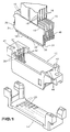
- a group of cable cards 10 are shown which are adapted to be arrayed and secured in a card grouper 12 which in turn presents the cable cards as a unit to a connector housing 14.
- Each of the cable cards 10 is adapted to receive flat cables 16 at one end thereof and provide connection means 18 at the opposite thereon for connection to various types of connectors such as bifurcated spring connector 20 which are arrayed in the connector housing 14.
- connection means 18 can engage the proper connector 20 on the housing 14.
- each of the cable cards 10 is comprised of a pair of flat plate members 22 and 23 adapted to receive between them the flat cables.
- the plates 22 and 23 are secured together such as by adhesives or by ultrasonic or fusion bonding.
- guide pins 24 are provided on the plate member 22 with mating apertures 25 provided in the plate member 23 so as to precisely align the two plates 22 and 23 to form a cable card unit.
- the card grouper 12 is provided with a first set of parallel slots 26 extending down one side thereof and a second set of parallel slots 28 extending down the other side thereof.
- the slots 26 and 28 are arranged to receive slide members 30 formed on opposite sides of plate 23.
- the bottom side of the slide members 30 have a shoulder 31.
- the shoulder 31 acts as a polarizing device which will allow the cards to be inserted only in one orientation since if they are reversed the shoulder 31 will not fit into the respective slots 26 and 28 but will abut the surfaces 32 adjacent thereto.
- the plate 22 is provided with a pair of tabs 33 and 34 on opposite sides thereof and the plate 23 is provided with tabs 36 and 37 on opposite sides thereof.
- Each of the tabs are scored at four different positions so that they may be broken or cut off in increments to provide three separate extension distances from each side of their respective plates.
- Each of the tabs can be trimmed or programmed to the appropriate one of four lengths to provide the keying function wherein each separate cable card may be uniquely configured vis-a-vis the configuration of its four tabs so as to fit only into a given preselected position within the card grouper 12 as will be presently described.
- FIGs 4A, 4B, and 4C wherein a cable card is shown in various stages of being programmed or configured to a specific and unique configuration.
- the cable card is shown with all four tabs in their initial state and unprogrammed.
- the tabs 34 and 36 have been removed from the opposite ends of side plates 22 and 23 respectively.
- Figure 4C only the very end portion of tabs 33 and 37 have been removed.
- Each of the cards is programmed in a similar manner, however, to a different configuration so that each will uniquely fit into one and only one location of the card grouper 12.
- the card grouper includes a template portion 42 which has a series of ten locations for the reception of various cable cards 10.
- the template portion 42 may be molded into the top position of the card grouper as shown herein, or it may be formed as a separate sheet and attached to the top of the grouper.
- the template 42 at each location is provided with a pair of notches 44 and 46 on opposite sides thereof.
- Each of the notches 44 and 46 is sized and arranged such that it will receive only one programmed configuration of a programmed cable card.
- a properly programmed or trimmed cable card 10 fits into the slots and the notches to provide one and only one array, i.e. a unique sequence of the cards 10 within the grouper 12 as determined by the programming of the cards and the template of the grouper.
- Figure 6 depicts the situation where it is attempted to insert the cable card into a slot improperly oriented; i.e. reversed 180°. In this case the card cannot be inserted irrespective of the tab programming because the shoulder 31 abuts a surface 32 adjacent its groove.
- each plate 23 is provided with a resilient arm 48 which serves as a latch to latch against the undersurface 50 of the card grouper and prevent unintended withdrawal of each of the cards.
- Figure 7 shows a group of ten different cable cards inserted into a card grouper 12 wherein the card grouper has each of the ten locations uniquely configured to receive only the properly programmed and properly oriented cable card 10.
- the preferred embodiment utilizes a flat cable
- other types of cable e.g. twisted pair, tri-lead, etc. may be effectively utilized.
Landscapes
- Details Of Connecting Devices For Male And Female Coupling (AREA)
- Coupling Device And Connection With Printed Circuit (AREA)
- Multi-Conductor Connections (AREA)
- Supports Or Holders For Household Use (AREA)
Claims (7)
- Un système de sécurité comprenant une pluralité de cartes câblées (10) et un chargeur de cartes (12) pour assurer le montage dans la séquence appropriée desdites cartes câblées (10) dans ledit chargeur de cartes (12) et dans lequel chacune desdites cartes câblées (10) porte une pluralité de câbles (16) disposés à partir d'une extrémité de celles ci, l'autre extrémité des cartes comportant des moyens de connexion électrique (18) qui les prolongent, dans lequel:- ledit chargeur de cartes (12) comprend un moyen de support pour retenir une pluralité desdites cartes (10) côte à côte et former un ensemble de cartes, les moyens de connexion (18) desdites cartes étant alignés et se projetant depuis une extrémité dudit moyen de support,- ledit moyen de support comprend des premier et second ensembles (26, 20) d'une pluralité de raînures parallèles ménagées dans leurs côtés opposés pour recevoir les extrémités opposées desdites cartes (10) et les maintenir dans ledit ensemble,- des pattes (33, 34, 36, 37) sont formées à une extrémité de chacune desdites cartes (10) sur au moins l'un de ses bords,- lesdites pattes peuvent être sélectionnées pour se projeter à au moins deux distances différentes depuis le bord respectif de la carte,- ledit chargeur de cartes (12) comprend des moyens de calibrage (42) associés à celui ci et disposés de façon à fonctionner en association avec les pattes desdites cartes,- lesdits moyens de calibrage comportant une pluralité d'ensembles de raînures (44, 46), chaque ensemble de raînures étant configuré pour fonctionner en association avec la configuration des pattes d'une et une seule carte câblée.
- Le système de sécurité selon la revendication 1 dans lequel lesdites pattes (33, 34, 36, 37) de chaque carte comprennent au moins une patte se projetant depuis chaque côté de ladite carte.
- Le système de sécurité selon la revendication 2 dans lequel chaque carte comprend deux plaques (22, 23) juxtaposées face à face avec le câble disposé entre elles,
et dans lequel chacune desdites plaques présente une patte (33, 34, 36, 37) qui est individuellement sélectionnée pour se projeter à la distance désirée,
ce qui permet la disposition indépendante de deux configurations de pattes de chaque côté de la carte. - Le système de sécurité selon l'une quelconque des revendications précédentes comprenant en outre des moyens de polarisation pour ne permettre l'introduction de la carte dans sa raînure respective, que dans une seule orientation.
- Le système de sécurité selon la revendication 4 dans lequel lesdits moyens de polarisation comprennent des butées (32) formées sur ledit moyen de support et des épaulements (31) formés sur ledit chargeur de cartes et positionnés pour fonctionner en association avec lesdites butées afin d'interdire l'introduction de la carte dans une mauvaise orientation.
- Le système de sécurité selon l'une quelconque des revendications précédentes dans lequel lesdites pattes (33, 34, 36, 37) sont toutes initialement formées à la même longueur et des moyens sont prévus pour réduire de manière sélective et individuelle la longueur de chaque patte.
- Le système de sécurité selon l'une quelconque des revendications précédentes dans lequel des moyens sont prévus pour réduire de manière sélective les pattes (33, 34, 36, 37) à au moins deux longueurs plus courtes sélectionnées.
Applications Claiming Priority (2)
| Application Number | Priority Date | Filing Date | Title |
|---|---|---|---|
| US07/284,578 US4900274A (en) | 1988-12-15 | 1988-12-15 | Keying system for assuring proper array configuration of cable cards |
| US284578 | 1988-12-15 |
Publications (3)
| Publication Number | Publication Date |
|---|---|
| EP0373355A2 EP0373355A2 (fr) | 1990-06-20 |
| EP0373355A3 EP0373355A3 (fr) | 1991-01-09 |
| EP0373355B1 true EP0373355B1 (fr) | 1993-08-11 |
Family
ID=23090721
Family Applications (1)
| Application Number | Title | Priority Date | Filing Date |
|---|---|---|---|
| EP89120597A Expired - Lifetime EP0373355B1 (fr) | 1988-12-15 | 1989-11-07 | Système de détrompage |
Country Status (4)
| Country | Link |
|---|---|
| US (1) | US4900274A (fr) |
| EP (1) | EP0373355B1 (fr) |
| JP (1) | JPH0630271B2 (fr) |
| DE (1) | DE68908371T2 (fr) |
Families Citing this family (8)
| Publication number | Priority date | Publication date | Assignee | Title |
|---|---|---|---|---|
| FR2673050B1 (fr) * | 1991-02-15 | 1994-01-28 | Francelco | Bloc de connexion electrique enfichable et connecteur incorporant un tel bloc. |
| US5346412A (en) * | 1993-07-27 | 1994-09-13 | The Whitaker Corporation | Break away key and latch assembly |
| US6386924B2 (en) * | 2000-03-31 | 2002-05-14 | Tyco Electronics Corporation | Connector assembly with stabilized modules |
| US6352452B1 (en) * | 2000-07-12 | 2002-03-05 | Molex Incorporated And Tellabs Operations, Inc. | Connector module polarization assembly |
| TW486178U (en) | 2001-06-22 | 2002-05-01 | Hon Hai Prec Ind Co Ltd | Receptacle connector assembly |
| US20040147169A1 (en) * | 2003-01-28 | 2004-07-29 | Allison Jeffrey W. | Power connector with safety feature |
| US7160117B2 (en) * | 2004-08-13 | 2007-01-09 | Fci Americas Technology, Inc. | High speed, high signal integrity electrical connectors |
| JP2009518786A (ja) * | 2005-12-07 | 2009-05-07 | エフシーアイ | ケーブルコネクタ及びヘッダ |
Family Cites Families (15)
| Publication number | Priority date | Publication date | Assignee | Title |
|---|---|---|---|---|
| US3177461A (en) * | 1958-03-31 | 1965-04-06 | Adage Inc | Keying device |
| US3376565A (en) * | 1965-06-22 | 1968-04-02 | Sperry Rand Corp | Random access positioning apparatus for article selection |
| US3611272A (en) * | 1970-07-01 | 1971-10-05 | Bendix Corp | Polarizing means for mateable units such as electrical connectors |
| US3714617A (en) * | 1971-09-28 | 1973-01-30 | Bendix Corp | Snap in polarizing member for electrical connectors |
| US4032213A (en) * | 1976-01-29 | 1977-06-28 | The Bendix Corporation | Polarizing means for electrical connectors |
| EP0033286A3 (fr) * | 1980-01-28 | 1981-10-28 | The Bendix Corporation | Moyen de polarisation pour unités accouplables telles que connecteurs électriques |
| US4307927A (en) * | 1980-03-24 | 1981-12-29 | Rockwell International Corporation | Polarization key for electrical connector |
| JPS58111281A (ja) * | 1981-12-25 | 1983-07-02 | 本田技研工業株式会社 | カプラ−接続装置 |
| DE3315688C2 (de) * | 1982-09-29 | 1987-04-30 | Karl 7298 Loßburg Hehl | Elektrischer Steckverbinder |
| US4542441A (en) * | 1983-02-28 | 1985-09-17 | United Technologies Corporation | Card guide |
| US4726791A (en) * | 1987-04-24 | 1988-02-23 | Amp Incorporated | Polarizing system for connectors |
| US4773881A (en) * | 1987-05-21 | 1988-09-27 | Amp Incorporated | Keying system for connector assemblies |
| EP0317586B1 (fr) * | 1987-05-21 | 1993-09-01 | The Whitaker Corporation | Systeme de clavetage pour ensembles connecteurs |
| US4758928A (en) * | 1987-07-27 | 1988-07-19 | Motorola, Inc. | Mechanical interlock arrangement for preventing misinstallation of PC boards in an associated mainframe chassis |
| JPH01307182A (ja) * | 1988-06-02 | 1989-12-12 | Matsushita Electric Ind Co Ltd | プリント基板誤挿入防止装置 |
-
1988
- 1988-12-15 US US07/284,578 patent/US4900274A/en not_active Expired - Fee Related
-
1989
- 1989-11-07 DE DE89120597T patent/DE68908371T2/de not_active Expired - Fee Related
- 1989-11-07 EP EP89120597A patent/EP0373355B1/fr not_active Expired - Lifetime
- 1989-12-15 JP JP1324157A patent/JPH0630271B2/ja not_active Expired - Lifetime
Also Published As
| Publication number | Publication date |
|---|---|
| US4900274A (en) | 1990-02-13 |
| JPH02223170A (ja) | 1990-09-05 |
| DE68908371T2 (de) | 1994-03-17 |
| DE68908371D1 (de) | 1993-09-16 |
| EP0373355A2 (fr) | 1990-06-20 |
| JPH0630271B2 (ja) | 1994-04-20 |
| EP0373355A3 (fr) | 1991-01-09 |
Similar Documents
| Publication | Publication Date | Title |
|---|---|---|
| EP0130556B1 (fr) | Connecteur pour cicuits imprimés à force d'insertion nulle comprenant un système de détrompage | |
| EP0278868B1 (fr) | Connecteur haute densité à plusieurs rangées | |
| EP0371206B1 (fr) | Dispositif de connexion séquentielle | |
| EP0650230B1 (fr) | Loquet pour connecteur électrique | |
| US3660803A (en) | Electrical connectors | |
| EP0748527B1 (fr) | Connecteur de bords d'une carte a circuits imprimes assurant des connexions electriques non simultanees | |
| EP0871261B1 (fr) | Améliorations d'un connecteur multi-broches | |
| US5800186A (en) | Printed circuit board assembly | |
| US4377315A (en) | Circuit board keying arrangement | |
| US4335272A (en) | Breakaway circuit board with flexible coupling | |
| US5387132A (en) | Keyed card edge connector | |
| US5040997A (en) | Flex circuit connector assembly and method for manufacturing the same | |
| US4398779A (en) | Keying apparatus for interconnecting electrical components | |
| EP0373355B1 (fr) | Système de détrompage | |
| US6419503B1 (en) | Alignment device for use with connector | |
| US4611880A (en) | Multipiece electrical connector | |
| US4093330A (en) | Circuit chip receptacle | |
| US4915636A (en) | Card guide with electrical contacts | |
| US5350319A (en) | High-density printed circuit connector | |
| US4685031A (en) | Edgeboard connector | |
| EP0000623B1 (fr) | Connecteur en bordure pour circuit imprimé | |
| US4878153A (en) | Electronic shelf assembly | |
| EP0401585B1 (fr) | Dispositif à griffe pour connecteurs de circuit imprimés câblés | |
| US3378730A (en) | Printed circuit board assembly with releasable securing and engaging means | |
| US5368491A (en) | High density electrical connector |
Legal Events
| Date | Code | Title | Description |
|---|---|---|---|
| PUAI | Public reference made under article 153(3) epc to a published international application that has entered the european phase |
Free format text: ORIGINAL CODE: 0009012 |
|
| AK | Designated contracting states |
Kind code of ref document: A2 Designated state(s): DE FR GB |
|
| PUAL | Search report despatched |
Free format text: ORIGINAL CODE: 0009013 |
|
| 17P | Request for examination filed |
Effective date: 19901025 |
|
| AK | Designated contracting states |
Kind code of ref document: A3 Designated state(s): DE FR GB |
|
| 17Q | First examination report despatched |
Effective date: 19921014 |
|
| GRAA | (expected) grant |
Free format text: ORIGINAL CODE: 0009210 |
|
| AK | Designated contracting states |
Kind code of ref document: B1 Designated state(s): DE FR GB |
|
| REF | Corresponds to: |
Ref document number: 68908371 Country of ref document: DE Date of ref document: 19930916 |
|
| ET | Fr: translation filed | ||
| PLBE | No opposition filed within time limit |
Free format text: ORIGINAL CODE: 0009261 |
|
| STAA | Information on the status of an ep patent application or granted ep patent |
Free format text: STATUS: NO OPPOSITION FILED WITHIN TIME LIMIT |
|
| 26N | No opposition filed | ||
| PGFP | Annual fee paid to national office [announced via postgrant information from national office to epo] |
Ref country code: FR Payment date: 19951107 Year of fee payment: 7 |
|
| PGFP | Annual fee paid to national office [announced via postgrant information from national office to epo] |
Ref country code: DE Payment date: 19951123 Year of fee payment: 7 |
|
| PGFP | Annual fee paid to national office [announced via postgrant information from national office to epo] |
Ref country code: GB Payment date: 19961028 Year of fee payment: 8 |
|
| PG25 | Lapsed in a contracting state [announced via postgrant information from national office to epo] |
Ref country code: FR Effective date: 19970731 |
|
| PG25 | Lapsed in a contracting state [announced via postgrant information from national office to epo] |
Ref country code: DE Effective date: 19970801 |
|
| REG | Reference to a national code |
Ref country code: FR Ref legal event code: ST |
|
| PG25 | Lapsed in a contracting state [announced via postgrant information from national office to epo] |
Ref country code: GB Free format text: LAPSE BECAUSE OF NON-PAYMENT OF DUE FEES Effective date: 19971107 |
|
| GBPC | Gb: european patent ceased through non-payment of renewal fee |
Effective date: 19971107 |