EP0373370B1 - Dispositif pour déterminer la distance entre deux surfaces en connexion tant avec la moitié moulée supérieure qu'inférieure d'un outil à presser - Google Patents
Dispositif pour déterminer la distance entre deux surfaces en connexion tant avec la moitié moulée supérieure qu'inférieure d'un outil à presser Download PDFInfo
- Publication number
- EP0373370B1 EP0373370B1 EP89120968A EP89120968A EP0373370B1 EP 0373370 B1 EP0373370 B1 EP 0373370B1 EP 89120968 A EP89120968 A EP 89120968A EP 89120968 A EP89120968 A EP 89120968A EP 0373370 B1 EP0373370 B1 EP 0373370B1
- Authority
- EP
- European Patent Office
- Prior art keywords
- store
- pressure
- distance
- pressure source
- determining
- Prior art date
- Legal status (The legal status is an assumption and is not a legal conclusion. Google has not performed a legal analysis and makes no representation as to the accuracy of the status listed.)
- Expired - Lifetime
Links
- 238000003825 pressing Methods 0.000 title description 11
- 238000000465 moulding Methods 0.000 claims description 8
- 230000006835 compression Effects 0.000 claims 1
- 238000007906 compression Methods 0.000 claims 1
- 238000005259 measurement Methods 0.000 description 7
- 125000006850 spacer group Chemical group 0.000 description 6
- 230000000903 blocking effect Effects 0.000 description 3
- 150000001875 compounds Chemical class 0.000 description 3
- 238000003860 storage Methods 0.000 description 3
- 239000012530 fluid Substances 0.000 description 2
- 238000000034 method Methods 0.000 description 2
- 239000000203 mixture Substances 0.000 description 2
- 239000004033 plastic Substances 0.000 description 2
- 230000015572 biosynthetic process Effects 0.000 description 1
- 239000000356 contaminant Substances 0.000 description 1
- 238000011109 contamination Methods 0.000 description 1
- 238000006073 displacement reaction Methods 0.000 description 1
- 230000000694 effects Effects 0.000 description 1
- 239000011261 inert gas Substances 0.000 description 1
- 238000004519 manufacturing process Methods 0.000 description 1
- 230000003287 optical effect Effects 0.000 description 1
- 239000004810 polytetrafluoroethylene Substances 0.000 description 1
- 229920001343 polytetrafluoroethylene Polymers 0.000 description 1
- 238000011144 upstream manufacturing Methods 0.000 description 1
Images
Classifications
-
- B—PERFORMING OPERATIONS; TRANSPORTING
- B30—PRESSES
- B30B—PRESSES IN GENERAL
- B30B15/00—Details of, or accessories for, presses; Auxiliary measures in connection with pressing
-
- G—PHYSICS
- G01—MEASURING; TESTING
- G01B—MEASURING LENGTH, THICKNESS OR SIMILAR LINEAR DIMENSIONS; MEASURING ANGLES; MEASURING AREAS; MEASURING IRREGULARITIES OF SURFACES OR CONTOURS
- G01B13/00—Measuring arrangements characterised by the use of fluids
- G01B13/12—Measuring arrangements characterised by the use of fluids for measuring distance or clearance between spaced objects or spaced apertures
Definitions
- the invention relates to a device for determining the distance between two surfaces which are connected to the upper or to the lower mold half of a pressing tool, in particular for processing fiber-reinforced molding compositions, and which are matched to one another in such a way that the mold halves have the desired molding thickness Appropriate end position if the mutual distance between the surfaces has a limit.
- the distance measurement is associated with difficulties in the pressing tools for the processing of fiber-reinforced molding compositions, in that the pressing tools can easily have temperatures of up to 200 ° C. and contaminants to be removed at intervals in the pressing process attack. Both circumstances at least question the use of functionally reliable measuring devices.
- the invention has for its object to provide a device for determining the distance between two suitable surfaces on the upper or lower mold half of a press tool, which is less prone to failure, in particular insensitive to dirt and temperature, and which provides reliable measured values without special adjustment effort.
- the object is achieved by a device with the features of claim 1.
- the basic idea of the invention is then to connect a nozzle arranged in one of the two adjacent surfaces via a reservoir to a pressure source for a compressible fluid (in particular air or an inert gas) and - starting from an initial state in which the pressure source and the memory connected to the nozzle is subject to a specific, predetermined pressure - the period of time Measure within which the pressure applied to the accumulator has dropped to a specified lower value after switching off the pressure source. This time period is a measure of the mutual distance between the two surfaces assigned to the mold halves.
- the nozzle should be designed in such a way that it itself results in a considerably lower throttle resistance than the gap between the adjacent surfaces.
- a nozzle with a nozzle bore of the order of magnitude of 3 mm can be used to determine distances between the two surfaces that are no more than about 0.5 mm.
- the newly proposed device must also be designed in such a way that the aforementioned time measurement is carried out under reproducible circumstances that are as similar as possible; This presupposes, among other things, that the time measurement only begins when a quasi-steady state has occurred in the memory connected to the pressure source, in which the pressure applied to the memory has assumed a corresponding upper value.
- the control unit for determining the time span of the pressure drop is equipped with a pressure sensor which is connected in parallel with the memory (claim 2).
- the pressure source is expedient towards the Storage connected upstream of a shut-off valve, which can be switched into the blocking position depending on a predetermined upper value of the pressure applied to the storage (claim 3).
- the control unit can be equipped with an optical display which shows the pressure applied to the accumulator and, if a certain upper value is present, enables the pressure source to be switched off by actuating the shut-off valve by hand.
- the storage end is preferably fastened laterally to the body which bears the surface associated with the upper mold half (claim 4).
- the memory itself can be formed in a simple manner from a hose, in particular from a suitable, resistant plastic (preferably PTFE) (claim 5). Due to the lateral arrangement of the memory, the switching and control components of the measuring device can be arranged outside the area of high temperatures and outside the contamination area. Since only one of the bodies, which accommodate the opposing surfaces, has a nozzle with an easily produced nozzle bore, no adjustment problems can arise even if the thickness of the concerned body, for example by grinding. Due to the use of a hose as an accumulator, the sensitive components already mentioned can be attached to the press frame, for example, on the press frame without any special effort - and thus also less prone to failure.
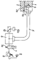
- the upper spacer is equipped with a nozzle 3 in the form of a nozzle bore, which is perpendicular to the surfaces 1a, 2a is aligned.
- the upper spacer 1 is further provided on its outward side with a connection hole 4 which, with the interposition of a plastic hose 5, a connecting piece 6, a shut-off valve 7 and a pressure control valve 8, is connected to a pressure source 9 (in the form of a compressed air pump) stands.
- the shut-off valve 7 assumes the blocking position shown in the rest position under the action of its closing spring 7a, in which the supply of compressed air to the store 5 is interrupted.
- the intermediate piece 6 is also connected to the pressure sensor (not shown) of a control unit 10, which makes the measured distance x visible via a display 10a.
- the control unit is designed in such a way that, after the compressed air supply has been interrupted by closing the shut-off valve 7, it measures the period of time within which the pressure (the so-called upper value) present at the store 5 when the pressure source 9 is switched off has dropped to a predetermined lower value .
- the measured period of time is a measure of the mutual distance x of the surfaces 1a and 2a; this distance value is made optically visible by means of the display 10a.
- the memory 5 is connected to the pressure source 9 until a quasi-steady state with the associated upper value of the pressure has been established. Only then is the shut-off valve 7 closed when the time measurement carried out by the control unit 10 is started. Meanwhile, depending on the size of the distance x between the surfaces 1a and 2a, the pressure within the reservoir drops more or less quickly.
- the control unit 10 can also be designed in such a way that it triggers the displacement of the shut-off valve 7 into the illustrated blocking position as soon as the pressure applied to the accumulator 5 has reached a certain predetermined upper value.
- the subject of the invention is used as a control element in such a way that at the end of a pressing process it is checked in the manner described above whether the surfaces in question are arranged at a distance from one another at this point in time and thus ensure that the pressing force is exclusively on the processing molding compound comes into effect.
Landscapes
- Physics & Mathematics (AREA)
- General Physics & Mathematics (AREA)
- Engineering & Computer Science (AREA)
- Mechanical Engineering (AREA)
- Casting Or Compression Moulding Of Plastics Or The Like (AREA)
- Moulds For Moulding Plastics Or The Like (AREA)
- Presses And Accessory Devices Thereof (AREA)
- Force Measurement Appropriate To Specific Purposes (AREA)
Claims (5)
- Dispositif pour déterminer la distance entre deux surfaces en connexion tant avec la moitié moulée supérieure qu'inférieure d'un outil à presser, en particulier destiné au façonnage de matières moulables renforcées par fibres, surfaces qui sont adaptées l'une sur l'autre de telle sorte que les moitiés moulées prennent la position finale correspondant à l'épaisseur souhaitée de la pièce usinée dans le cas où la distance réciproque des surfaces présente une valeur limite, caractérisé en ce que l'une des deux surfaces (la) présente une tuyère (3) alignée sur l'autre surface (2a) et qui peut être raccordée, par l'intermédiaire d'un réservoir (5), à une source de pression (9) à pression régulée pour un agent d'écoulement compressible, et en ce qu'est prévu un organe de commande (10) qui, dès la mise hors circuit de la source de pression, mesure l'intervalle de temps pendant lequel la pression existant dans le réservoir au moment de la mise hors circuit a baissé pour atteindre une valeur inférieure donnée.
- Dispositif selon la revendication 1, caractérisé en ce que l'organe de commande (10) présente un capteur de pression qui est monté en parallèle avec le réservoir (5).
- Dispositif selon au moins l'une des revendications 1 à 2, caractérisé en ce que la source de pression (9) est équipée d'une soupape d'arrêt (7) qui peut être commutée en position de blocage - en fonction d'une valeur supérieure donnée de la pression existant dans le réservoir (5).
- Dispositif selon au moins l'une des revendications 1 à 3, caractérisé en ce que le réservoir (5) est fixé latéralement, par son extrémité de sortie, au corps (1) qui porte la surface (1a) appartenant à la moitié moulée supérieure.
- Dispositif selon au moins l'une des revendications 1 à 4, caractérisé en ce que le réservoir est formé d'un tuyau flexible (5).
Applications Claiming Priority (2)
| Application Number | Priority Date | Filing Date | Title |
|---|---|---|---|
| DE3841327A DE3841327A1 (de) | 1988-12-08 | 1988-12-08 | Einrichtung zur bestimmung des abstandes zwischen zwei flaechen, die mit der oberen beziehungsweise mit der unteren formhaelfte eines presswerkzeugs in verbindung stehen |
| DE3841327 | 1988-12-08 |
Publications (2)
| Publication Number | Publication Date |
|---|---|
| EP0373370A1 EP0373370A1 (fr) | 1990-06-20 |
| EP0373370B1 true EP0373370B1 (fr) | 1993-03-17 |
Family
ID=6368708
Family Applications (1)
| Application Number | Title | Priority Date | Filing Date |
|---|---|---|---|
| EP89120968A Expired - Lifetime EP0373370B1 (fr) | 1988-12-08 | 1989-11-11 | Dispositif pour déterminer la distance entre deux surfaces en connexion tant avec la moitié moulée supérieure qu'inférieure d'un outil à presser |
Country Status (5)
| Country | Link |
|---|---|
| US (1) | US5014546A (fr) |
| EP (1) | EP0373370B1 (fr) |
| JP (1) | JPH02202410A (fr) |
| DE (2) | DE3841327A1 (fr) |
| ES (1) | ES2038815T3 (fr) |
Families Citing this family (2)
| Publication number | Priority date | Publication date | Assignee | Title |
|---|---|---|---|---|
| DE102005002448B4 (de) * | 2005-01-18 | 2010-04-22 | F.A.T. Fluide-Anwendungs-Technik Gmbh & Co. Kg | Vorrichtung und Verfahren zum Messen, Steuern oder Prüfen |
| US20080097263A1 (en) * | 2005-04-12 | 2008-04-24 | Grigoriev Anatoly I | Device for mechanical stimulation of the foot support areas |
Family Cites Families (5)
| Publication number | Priority date | Publication date | Assignee | Title |
|---|---|---|---|---|
| CH241935A (fr) * | 1942-12-04 | 1946-04-15 | Sa Etavex | Appareil de mesure pneumatique. |
| GB1122115A (en) * | 1966-06-02 | 1968-07-31 | Louis Eugene Camille Alfred Wa | Improvements in gauging apparatus |
| DE2014071A1 (de) * | 1970-03-24 | 1971-10-07 | Bayer | Pneumatische Schichtdickenmessung |
| DE2341581A1 (de) * | 1973-08-17 | 1975-02-27 | Philips Patentverwaltung | Vorrichtung zur ueberwachung der werkzeugbewegungen an arbeitsmaschinen |
| US4076780A (en) * | 1977-01-27 | 1978-02-28 | General Motors Corporation | Programmable velocity and force control method for compression molding |
-
1988
- 1988-12-08 DE DE3841327A patent/DE3841327A1/de not_active Withdrawn
-
1989
- 1989-11-11 ES ES198989120968T patent/ES2038815T3/es not_active Expired - Lifetime
- 1989-11-11 DE DE8989120968T patent/DE58903812D1/de not_active Expired - Fee Related
- 1989-11-11 EP EP89120968A patent/EP0373370B1/fr not_active Expired - Lifetime
- 1989-12-04 US US07/444,856 patent/US5014546A/en not_active Expired - Fee Related
- 1989-12-07 JP JP1316608A patent/JPH02202410A/ja active Pending
Also Published As
| Publication number | Publication date |
|---|---|
| JPH02202410A (ja) | 1990-08-10 |
| DE58903812D1 (de) | 1993-04-22 |
| ES2038815T3 (es) | 1993-08-01 |
| US5014546A (en) | 1991-05-14 |
| EP0373370A1 (fr) | 1990-06-20 |
| DE3841327A1 (de) | 1990-06-13 |
Similar Documents
| Publication | Publication Date | Title |
|---|---|---|
| EP2588297B1 (fr) | Dispositif permettant de mettre en oeuvre un procédé de moulage par transfert de résine (rtm) et procédé de moulage par transfert de résine (rtm) | |
| DE102004028100A1 (de) | Extrusionsblaskopf | |
| CH706263A1 (de) | Tellerfadenbremse mit Reinigungseinrichtung. | |
| EP1083403A1 (fr) | Procédé et dispositif pour déterminer l'angle de pli d'un objet | |
| EP0945246B1 (fr) | Dispositif de fabrication avec unités de contrôle pour corps creux en matière plastique | |
| EP0373370B1 (fr) | Dispositif pour déterminer la distance entre deux surfaces en connexion tant avec la moitié moulée supérieure qu'inférieure d'un outil à presser | |
| EP3769054B1 (fr) | Procédé de fonctionnement d'un conteneur | |
| DE3425459A1 (de) | Verfahren zur ueberwachung und/oder regelung des spritzgiessens bei spritzgiessmaschinen | |
| DE3745138C2 (de) | Folienblasanlage zur Herstellung von Kunststoffolien | |
| DE29618980U1 (de) | Sprüheinrichtung | |
| DE10215946B4 (de) | Rheologische Messeinrichtung für eine Spritzgießmaschine | |
| DE102019208475A1 (de) | Vorrichtung zum Herstellen und Verarbeiten eines Mehrkomponentengemisches und Verfahren zum Betreiben einer derartigen Vorrichtung | |
| DE3530919A1 (de) | Betaetigungsvorrichtung fuer eine anpressrolle einer papierbahnzusammensetzvorrichtung in einer druckmaschine | |
| DE102019102246A1 (de) | Verfahren und Vorrichtung zum Spritzgießen von Kunststoffmaterialien | |
| EP0658742B1 (fr) | Dispositif pour contrÔler des machines à creuser le tunnel | |
| EP3768610A1 (fr) | Conteneur et son procédé de fonctionnement | |
| DE2049172C3 (de) | Einrichtung für die Anzeige der Verstopfung eines Druckflüssigkeitsfilters | |
| DE69617410T2 (de) | Verfahren und Vorrichtung zur Herstellung eines Gegenstandes aus elastomerem Werkstoff | |
| DE3429873A1 (de) | Einrichtung zur steuerung und/oder begrenzung der formauftriebskraft an spritzgiessmaschinen | |
| WO1997039832A1 (fr) | Pulverisateur, en particulier pour un robot d'assemblage | |
| DE3532933C2 (fr) | ||
| DE2029649C3 (de) | Zustelleinrichtung an einer Schleifmaschine | |
| DE69326412T2 (de) | Verfahren und Anlage zum Filtern eines chemischen Produktes, wie ein Lösungsmittel oder dergleichen, ohne Benutzung von Pumpen | |
| DE926392C (de) | Vorrichtung zum Messen des Spritzdruckes in Spritzmaschinen | |
| EP3825645B1 (fr) | Dispositif de détection d'un joint sur un brin de matériau flexible constitué d'une pluralité de sections de brin interconnectées |
Legal Events
| Date | Code | Title | Description |
|---|---|---|---|
| PUAI | Public reference made under article 153(3) epc to a published international application that has entered the european phase |
Free format text: ORIGINAL CODE: 0009012 |
|
| AK | Designated contracting states |
Kind code of ref document: A1 Designated state(s): DE ES FR IT SE |
|
| 17P | Request for examination filed |
Effective date: 19901129 |
|
| 17Q | First examination report despatched |
Effective date: 19920514 |
|
| RAP1 | Party data changed (applicant data changed or rights of an application transferred) |
Owner name: UMFORMTECHNIK ERFURT GMBH |
|
| GRAA | (expected) grant |
Free format text: ORIGINAL CODE: 0009210 |
|
| AK | Designated contracting states |
Kind code of ref document: B1 Designated state(s): DE ES FR IT SE |
|
| REF | Corresponds to: |
Ref document number: 58903812 Country of ref document: DE Date of ref document: 19930422 |
|
| ET | Fr: translation filed | ||
| ITF | It: translation for a ep patent filed | ||
| REG | Reference to a national code |
Ref country code: ES Ref legal event code: FG2A Ref document number: 2038815 Country of ref document: ES Kind code of ref document: T3 |
|
| PLBE | No opposition filed within time limit |
Free format text: ORIGINAL CODE: 0009261 |
|
| STAA | Information on the status of an ep patent application or granted ep patent |
Free format text: STATUS: NO OPPOSITION FILED WITHIN TIME LIMIT |
|
| 26N | No opposition filed | ||
| EAL | Se: european patent in force in sweden |
Ref document number: 89120968.6 |
|
| PGFP | Annual fee paid to national office [announced via postgrant information from national office to epo] |
Ref country code: SE Payment date: 19961003 Year of fee payment: 8 |
|
| PGFP | Annual fee paid to national office [announced via postgrant information from national office to epo] |
Ref country code: FR Payment date: 19961010 Year of fee payment: 8 |
|
| PGFP | Annual fee paid to national office [announced via postgrant information from national office to epo] |
Ref country code: ES Payment date: 19961106 Year of fee payment: 8 |
|
| PG25 | Lapsed in a contracting state [announced via postgrant information from national office to epo] |
Ref country code: ES Free format text: LAPSE BECAUSE OF EXPIRATION OF PROTECTION Effective date: 19971112 Ref country code: SE Free format text: LAPSE BECAUSE OF NON-PAYMENT OF DUE FEES Effective date: 19971112 |
|
| PG25 | Lapsed in a contracting state [announced via postgrant information from national office to epo] |
Ref country code: FR Free format text: THE PATENT HAS BEEN ANNULLED BY A DECISION OF A NATIONAL AUTHORITY Effective date: 19971130 |
|
| EUG | Se: european patent has lapsed |
Ref document number: 89120968.6 |
|
| REG | Reference to a national code |
Ref country code: FR Ref legal event code: ST |
|
| REG | Reference to a national code |
Ref country code: ES Ref legal event code: FD2A Effective date: 20010301 |
|
| PG25 | Lapsed in a contracting state [announced via postgrant information from national office to epo] |
Ref country code: IT Free format text: LAPSE BECAUSE OF NON-PAYMENT OF DUE FEES;WARNING: LAPSES OF ITALIAN PATENTS WITH EFFECTIVE DATE BEFORE 2007 MAY HAVE OCCURRED AT ANY TIME BEFORE 2007. THE CORRECT EFFECTIVE DATE MAY BE DIFFERENT FROM THE ONE RECORDED. Effective date: 20051111 |
|
| PGFP | Annual fee paid to national office [announced via postgrant information from national office to epo] |
Ref country code: DE Payment date: 20080131 Year of fee payment: 19 |
|
| PG25 | Lapsed in a contracting state [announced via postgrant information from national office to epo] |
Ref country code: DE Free format text: LAPSE BECAUSE OF NON-PAYMENT OF DUE FEES Effective date: 20090603 |