EP0373530A2 - Conveyor element with pins for receiving and conveying cops or empty bobbins - Google Patents
Conveyor element with pins for receiving and conveying cops or empty bobbins Download PDFInfo
- Publication number
- EP0373530A2 EP0373530A2 EP89122684A EP89122684A EP0373530A2 EP 0373530 A2 EP0373530 A2 EP 0373530A2 EP 89122684 A EP89122684 A EP 89122684A EP 89122684 A EP89122684 A EP 89122684A EP 0373530 A2 EP0373530 A2 EP 0373530A2
- Authority
- EP
- European Patent Office
- Prior art keywords
- sleeve
- transport element
- receiving
- sleeve pin
- element according
- Prior art date
- Legal status (The legal status is an assumption and is not a legal conclusion. Google has not performed a legal analysis and makes no representation as to the accuracy of the status listed.)
- Withdrawn
Links
Images

Classifications
-
- D—TEXTILES; PAPER
- D01—NATURAL OR MAN-MADE THREADS OR FIBRES; SPINNING
- D01H—SPINNING OR TWISTING
- D01H9/00—Arrangements for replacing or removing bobbins, cores, receptacles, or completed packages at paying-out or take-up stations ; Combination of spinning-winding machine
- D01H9/18—Arrangements for replacing or removing bobbins, cores, receptacles, or completed packages at paying-out or take-up stations ; Combination of spinning-winding machine for supplying bobbins, cores, receptacles, or completed packages to, or transporting from, paying-out or take-up stations ; Arrangements to prevent unwinding of roving from roving bobbins
- D01H9/187—Arrangements for replacing or removing bobbins, cores, receptacles, or completed packages at paying-out or take-up stations ; Combination of spinning-winding machine for supplying bobbins, cores, receptacles, or completed packages to, or transporting from, paying-out or take-up stations ; Arrangements to prevent unwinding of roving from roving bobbins on individual supports, e.g. pallets
Definitions
- the invention relates to a transport element with sleeve pins for receiving and transporting cops or empty sleeves arranged on sleeves on spinning machines, in particular conveyor belts.
- the position of the sleeve pins relative to the loading and unloading devices must be reliably located. With mechanical or optical sensors, this was not possible reliably enough, since experience has shown that the inevitable contamination in the spinning mill affects its function.
- the invention has for its object to design the sleeve pin so that the sleeve pin is easily recognizable.
- the sleeve pins have at least one recess for the optional incorporation of a trigger element which interacts with a sensor device on the path of movement of the transport element.
- This combination of sleeve pin and release element makes it possible to locate the position of the sleeve pin in the correct function and, if necessary, to recognize their type of assembly, which significantly improves the functional reliability of automation.
- the cutout can be arranged between a central bore for receiving a fastening element engaging in the sleeve pin and the outer circumference of the sleeve pin, wherein the release element embedded in the sleeve pin can be designed, for example, as an FE-metallic switching element.
- the switching element can be U-shaped, for example, and arranged transversely to the direction of travel of the transport element. One of these two legs can cooperate with the aforementioned sensor device, so that the sleeve pin can be easily recognized.
- the two legs of the switching element can each lie in a recess in the sleeve pin in a rotationally fixed manner.
- the switching element in its web connecting its two legs has an out-of-round opening which interacts with a correspondingly out-of-round contour of a torsionally fixed sleeve pin, so that a correct and functionally correct positioning of the release element is ensured.
- a sleeve pin 1 On the transport element shown in FIG. 2, for example a conveyor belt 2, a sleeve pin 1 is arranged, which has a threaded central bore 6 and a foot 4 extending through an opening 16 of the conveyor belt 2 and a threaded bolt 5 on the conveyor belt 2 is secured against rotation.
- a sleeve 3 can be plugged onto this sleeve pin 1, which sleeve is an empty sleeve according to FIG. 2, for example.
- the sleeve pin has two mutually opposite recesses 7, 7 '.
- the two legs 11 and 12 are arranged transversely to the running direction R of the transport element 2. 2, there is the possibility that a sensor 15 interacts, for example, with the leg 11 of the switching element 8 made of FE metal and thus the sleeve pin 1 in question can be recognized.
- the web 13 of the release element 8 which connects the two legs 11 and 12 to one another, has a central bore 14 through which, according to FIG. 2, the threaded bolt 5 extends, which connects the sleeve pin 1 with the foot 4 secured against rotation on the conveyor belt 2.
- the sleeve pin 1 has only one recess in which a correspondingly designed trigger element 8 is embedded.
- the trigger element 8, which acts as a switching element, can also have, instead of the bore 14 in the web 13, a non-circular opening, which interacts with a correspondingly non-circular contour of a sleeve pin fixed in a rotationally fixed manner.
- the trigger element 8, which acts as a switching element can be designed, for example, as a sheet metal part, for reasons of cost savings.
Landscapes
- Engineering & Computer Science (AREA)
- Mechanical Engineering (AREA)
- Textile Engineering (AREA)
- Spinning Or Twisting Of Yarns (AREA)
- Replacing, Conveying, And Pick-Finding For Filamentary Materials (AREA)
- Belt Conveyors (AREA)
Abstract
Die Erfindung bezieht sich auf ein Transportelement 2 mit Hülsenzapfen 1 zum Aufnehmen und Transportieren von auf Hülsen 3 angeordneten Kopsen oder Leerhülsen an Spinnereimaschinen, insbesondere auf ein Transportband. Hierbei weisen die Hülsenzapfen 1 mindestens eine Aussparung 7, 7′ zur wahlweisen Einlagerung eines mit einer Sensoreinrichtung 15 am Bewegungsweg des Transportelements 2 zusammenwirkenden Auslöseelements 8 auf. 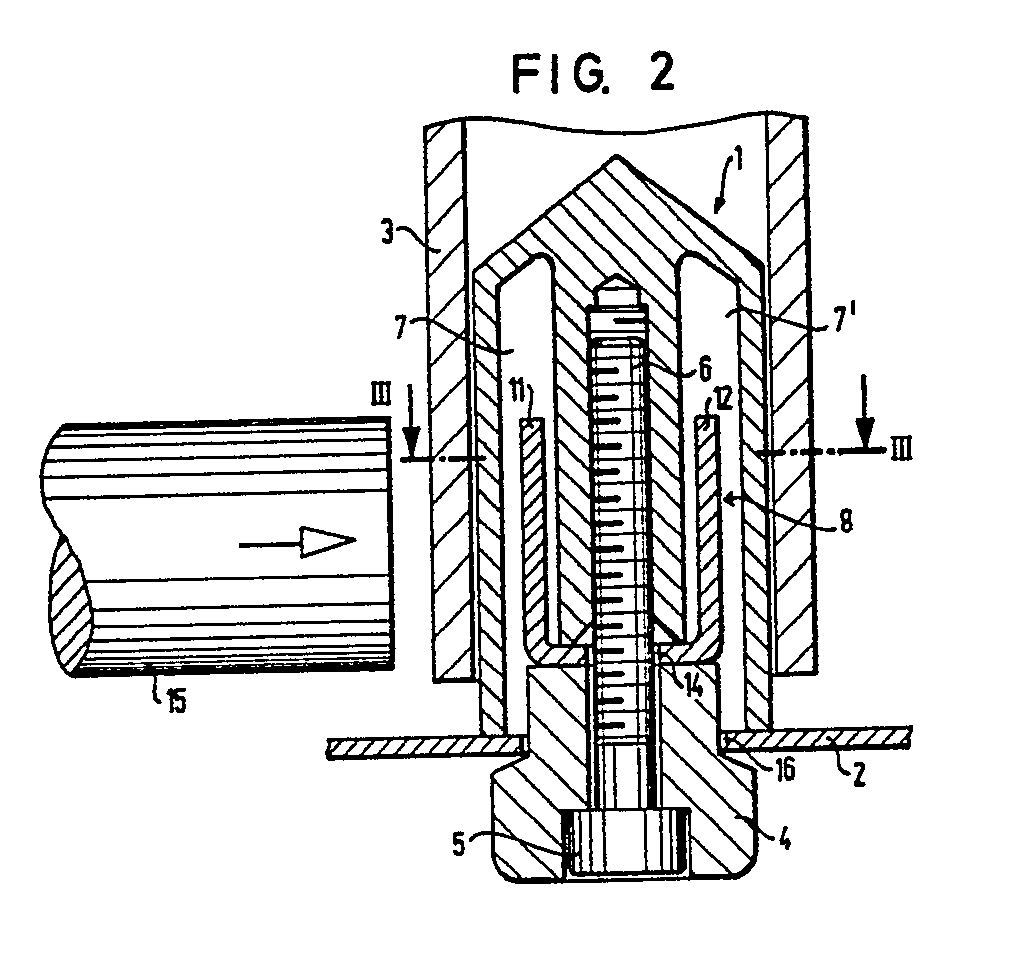
Description
Die Erfindung bezieht sich auf ein Transportelement mit Hülsenzapfen zum Aufnehmen und Transportieren von auf Hülsen angeordneten Kopsen oder Leerhülsen an Spinnereimaschinen, insbesondere Transportband.The invention relates to a transport element with sleeve pins for receiving and transporting cops or empty sleeves arranged on sleeves on spinning machines, in particular conveyor belts.
Um die Hülsenzapfen funktionssicher mit leeren Hülsen oder vollen Kopsen bestücken zu können oder volle Kopse oder leere Hülsen funktionssicher von den Hülsenzapfen entnehmen zu können, muß die Stellung der Hülsenzapfen zu den Bestückungs- bzw. Entnahmevorrichtungen zuverlässig geortet werden können. Mit mechanischen oder optischen Fühlern war dies nicht zuverlässig genug möglich, da die in der Spinnerei unvermeidliche Verschmutzung deren Funktion erfahrungsgemäß beeinträchtigt.In order to be able to equip the sleeve pins functionally reliably with empty sleeves or full capsules or to be able to remove full capsules or empty sleeves from the sleeve pins in a functionally reliable manner, the position of the sleeve pins relative to the loading and unloading devices must be reliably located. With mechanical or optical sensors, this was not possible reliably enough, since experience has shown that the inevitable contamination in the spinning mill affects its function.
Darüber hinaus war es schwierig, die aus Gründen der Einheitlichkeit gleich ausgeführten Hülsenzapfen für leere Hülsen und volle Kopse sicher genug unterscheiden zu können. Dies ist beispielsweise für das Bestücken mit leeren Hülsen wichtig, wenn etwa nur jeder zweite, an einer Bestückungsvorrichtung vorbeigeführte Hülsenzapfen mit einer leeren Hülse bestückt werden soll.In addition, it was difficult to distinguish the sleeve pins for empty sleeves and full heads, which were of the same design for reasons of uniformity. This is important, for example, for filling with empty sleeves, if only every second sleeve pin that is guided past an insertion device is to be fitted with an empty sleeve.
Demgegenüber liegt der Erfindung die Aufgabe zugrunde, die Hülsenzapfen so zu gestalten, daß auf einfache Weise eine gute Erkennbarkeit der Hülsenzapfen geschaffen wird.In contrast, the invention has for its object to design the sleeve pin so that the sleeve pin is easily recognizable.
Diese Aufgabe wird erfindungsgemäß dadurch gelöst, daß die Hülsenzapfen mindestens eine Aussparung zur wahlweisen Einlagerung eines mit einer Sensoreinrichtung am Bewegungsweg des Transportelementes zusammenwirkenden Auslöseelements aufweisen. Durch diese Kombination Hülsenzapfen - Auslöseelement ist es möglich, die Stellung der Hülsenzapfen funktionsrichtig zu orten und ggf. deren Bestückungsart zu erkennen, wodurch die Funktionssicherheit einer Automatisierung wesentlich verbessert wird.This object is achieved according to the invention in that the sleeve pins have at least one recess for the optional incorporation of a trigger element which interacts with a sensor device on the path of movement of the transport element. This combination of sleeve pin and release element makes it possible to locate the position of the sleeve pin in the correct function and, if necessary, to recognize their type of assembly, which significantly improves the functional reliability of automation.
Hierbei kann die Aussparung zwischen einer Mittelbohrung zur Aufnahme eines in den Hülsenzapfen eingreifenden Befestigungselements und dem Außenumfang des Hülsenzapfens angeordnet sein, wobei das in den Hülsenzapfen eingelagerte Auslöseelement beispielsweise als FE-metallisches Schaltglied ausgebildet sein kann. Es ergibt sich damit ein einfacher konstruktiver Aufbau ohne zusätzlichen Mehraufwand. Das Schaltglied kann beispielsweise U-förmig ausgebildet und quer zur Laufrichtung des Transportelements angeordnet sein. Einer dieser beiden Schenkel kann mit der vorgenannten Sensoreinrichtung zusammenwirken, so daß auf einfache Weise eine gute Erkennbarkeit der Hülsenzapfen ermöglicht wird.In this case, the cutout can be arranged between a central bore for receiving a fastening element engaging in the sleeve pin and the outer circumference of the sleeve pin, wherein the release element embedded in the sleeve pin can be designed, for example, as an FE-metallic switching element. This results in a simple construction without additional effort. The switching element can be U-shaped, for example, and arranged transversely to the direction of travel of the transport element. One of these two legs can cooperate with the aforementioned sensor device, so that the sleeve pin can be easily recognized.
Hierbei können die beiden Schenkel des Schaltgliedes verdrehungsfest in jeweils einer Aussparung des Hülsenzapfens liegen. Alternativ besteht die Möglichkeit, daß das Schaltglied in seinem, seine beiden Schenkel verbindenden Steg einen unrunden Durchbruch aufweist, der mit einer entsprechend unrunden Kontur eines verdrehungsfest befestigten Hülsenzapfens zusammenwirkt, so daß eine einwandfreie und funktionsrichtige Positionierung des Auslöseelements gewährleistet ist.In this case, the two legs of the switching element can each lie in a recess in the sleeve pin in a rotationally fixed manner. Alternatively, there is the possibility that the switching element in its web connecting its two legs has an out-of-round opening which interacts with a correspondingly out-of-round contour of a torsionally fixed sleeve pin, so that a correct and functionally correct positioning of the release element is ensured.
Bei einem Transportelement mit Hülsenzapfen zum Aufnehmen von auf Hülsen angeordneten Kopsen und mit Hülsenzapfen zum Aufnehmen von Leerhülsen besteht die Möglichkeit, daß nur die Hülsenzapfen der einen Art mit Schaltgliedern ausgestattet sind, wodurch vorteilhafterweise die Schaltglieder nicht nur zum Positionieren, sondern auch zum Unterscheiden der Hülsenzapfen dienen können.In the case of a transport element with sleeve journals for receiving copes arranged on sleeves and with sleeve journals for receiving empty sleeves, there is the possibility that only the sleeve journals of the one type are equipped with switching elements, which advantageously means that the switching elements not only for positioning but also for differentiating the sleeve journals can serve.
Die Erfindung wird nachfolgend anhand eines in der Zeichnung dargestellten Ausführungsbeispiels näher beschrieben. In der Zeichnung zeigen:
- Fig. 1 eine perspektivische Ansicht eines Auslöseelements;
- Fig. 2 einen Querschnitt durch ein Transportelement mit Hülsenzapfen und Hülse sowie Auslöseelement;
- Fig. 3 einen Schnitt gemäß der Linie III-III in Fig. 2.
- Figure 1 is a perspective view of a trigger element.
- Figure 2 shows a cross section through a transport element with sleeve pin and sleeve and trigger element.
- 3 shows a section along the line III-III in FIG. 2.
Auf dem in Fig. 2 dargestellten Transportelement, beispielsweise einem Transportband 2, ist ein Hülsenzapfen 1 angeordnet, welcher über eine mit Gewinde versehene Mittelbohrung 6 und einen sich durch eine Öffnung 16 des Transportbandes 2 erstreckenden Fuß 4 sowie über einen Gewindebolzen 5 an dem Transportband 2 verdrehsicher befestigt ist. Auf diesen Hülsenzapfen 1 ist eine Hülse 3 aufsteckbar, welche beispielsweise nach Fig. 2 eine Leerhülse ist.On the transport element shown in FIG. 2, for example a conveyor belt 2, a sleeve pin 1 is arranged, which has a threaded
Der Hülsenzapfen weist zwei einander gegenüberliegende Aussparungen 7, 7′ auf. In diese Aussparungen ragen Schenkel 11 und 12 eines in Fig. 1 perspektivisch dargestellten Auslöseelements 8, welches als U-förmig ausgebildetes Schaltglied gestaltet ist.The sleeve pin has two mutually opposite recesses 7, 7 '.
Wie aus Fig. 2 und 3 ersichtlich, sind die beiden Schenkel 11 und 12 quer zur Laufrichtung R des Transportelements 2 angeordnet. Damit besteht nach Fig. 2 die Möglichkeit, daß ein Sensor 15 beispielsweise mit dem aus FE-Metall bestehenden Schenkel 11 des Schaltgliedes 8 zusammenwirkt und somit eine Erkennbarkeit des betreffenden Hülsenzapfens 1 gegeben ist.As can be seen from FIGS. 2 and 3, the two
Wie aus Fig. 1 hervorgeht, weist der Steg 13 des Auslöseelements 8, welcher die beiden Schenkel 11 und 12 miteinander verbindet, eine zentrische Bohrung 14 auf, durch welche sich nach Fig. 2 der Gewindebolzen 5 erstreckt, der den Hülsenzapfen 1 mit dem Fuß 4 verdrehsicher auf dem Transportband 2 befestigt.As can be seen from FIG. 1, the
Alternativ zu der Ausführungsform nach Fig. 1 bis 3 besteht auch die Möglichkeit, daß der Hülsenzapfen 1 nur eine Aussparung aufweist, in welche ein entsprechend gestaltetes Auslöseelement 8 eingelagert ist.As an alternative to the embodiment according to FIGS. 1 to 3, there is also the possibility that the sleeve pin 1 has only one recess in which a correspondingly designed
Das als Schaltglied wirkende Auslöseelement 8 kann darüber hinaus statt der Bohrung 14 im Steg 13 einen unrunden Durchbruch aufweisen, welcher mit einer entsprechend unrunden Kontur eines verdrehungsfest befestigten Hülsenzapfens zusammenwirkt. Das als Schaltglied wirkende Auslöseelement 8 kann aus Kostenersparnisgründen beispielsweise als Blechformteil ausgebildet sein.The
Es besteht auch die Möglichkeit, daß auf dem Transportband 2 Hülsenzapfen zum Aufnehmen von auf Hülsen angeordneten Kopsen und Hülsenzapfen zum Aufnehmen von Leerhülsen angeordnet sind. Hierbei können in weiterer Ausgestaltung der Erfindung nur die Hülsenzapfen der einen Art mit den als Schaltgliedern wirkenden Auslöseelementen 8 ausgestattet sein, wodurch diese Schaltglieder vorteilhafterweise nicht nur zum Positionieren, sondern auch zum Unterscheiden der jeweiligen Hülsenzapfenarten dienen können.There is also the possibility that 2 sleeve journals for receiving cops arranged on sleeves and sleeve journals for receiving empty sleeves are arranged on the conveyor belt. In a further embodiment of the invention, only the sleeve pins of one type can be equipped with the
Insgesamt ergibt sich, daß durch die besondere Gestaltung des Hülsenzapfens 1 mit seinen Ausnehmungen 7 und 7′ sowie durch die Einbringung eines Auslöseelements 8, das als Schaltglied wirkt, eine gute Erkennbarkeit der Hülsenzapfen über eine Sensoreinrichtung 15 gewährleistet ist, wodurch eine weitere Verbesserung des Funktionsablaufes in Richtung Automatisierung gegeben ist.Overall, it follows that the special design of the sleeve pin 1 with its recesses 7 and 7 'and the introduction of a
Claims (8)
Applications Claiming Priority (2)
| Application Number | Priority Date | Filing Date | Title |
|---|---|---|---|
| DE3841812 | 1988-12-12 | ||
| DE3841812A DE3841812A1 (en) | 1988-12-12 | 1988-12-12 | TRANSPORT ELEMENT WITH SLEEVE PIN FOR RECEIVING AND TRANSPORTING COPS OR EMPTY SLEEVES SLEEVED ON SLEEVES |
Publications (2)
| Publication Number | Publication Date |
|---|---|
| EP0373530A2 true EP0373530A2 (en) | 1990-06-20 |
| EP0373530A3 EP0373530A3 (en) | 1990-11-28 |
Family
ID=6368988
Family Applications (1)
| Application Number | Title | Priority Date | Filing Date |
|---|---|---|---|
| EP19890122684 Withdrawn EP0373530A3 (en) | 1988-12-12 | 1989-12-08 | Conveyor element with pins for receiving and conveying cops or empty bobbins |
Country Status (4)
| Country | Link |
|---|---|
| US (1) | US4984422A (en) |
| EP (1) | EP0373530A3 (en) |
| JP (1) | JPH02210032A (en) |
| DE (1) | DE3841812A1 (en) |
Families Citing this family (5)
| Publication number | Priority date | Publication date | Assignee | Title |
|---|---|---|---|---|
| CH684699A5 (en) * | 1991-06-02 | 1994-11-30 | Rieter Ag Maschf | Apparatus for transporting tubes, bobbins or cops. |
| DE4131527A1 (en) * | 1991-09-21 | 1993-03-25 | Schlafhorst & Co W | CADDY FOR THE INDEPENDENT INDIVIDUAL TRANSPORTATION OF COPS AND COPPER SLEEVES IN A TRANSPORT SYSTEM OF A TEXTILE MACHINE |
| DE19636661A1 (en) * | 1996-09-10 | 1998-03-12 | Schlafhorst & Co W | Transport system for a textile machine |
| JP5076396B2 (en) * | 2006-08-10 | 2012-11-21 | 日本精工株式会社 | Rolling bearing unit for wheel support |
| CN106283296A (en) * | 2016-10-10 | 2017-01-04 | 江阴市华方新技术科研有限公司 | Spinning frame seat of reel assembly |
Family Cites Families (11)
| Publication number | Priority date | Publication date | Assignee | Title |
|---|---|---|---|---|
| DD110900A1 (en) * | 1973-08-10 | 1975-01-12 | ||
| NL7603705A (en) * | 1976-04-08 | 1977-10-11 | Ir Rudolph Abraham Hulscher | PROCEDURE FOR SORTING SPIN COPS, AND SPIDER SHELLS FOR USE THEREIN. |
| US4681231A (en) * | 1982-12-08 | 1987-07-21 | Murata Kikai Kabushiki Kaisha | Article selecting and conveying system |
| EP0124653B1 (en) * | 1983-05-06 | 1986-11-26 | Maschinenfabrik Rieter Ag | Device for depositing textile tubes on a conveyor belt |
| IN164144B (en) * | 1984-05-18 | 1989-01-21 | Rieter Ag Maschf | |
| DE3418814A1 (en) * | 1984-05-19 | 1985-11-21 | W. Schlafhorst & Co, 4050 Mönchengladbach | Apparatus for the ordered removal and supply of cross-wound bobbins of different batches |
| JPH0726263B2 (en) * | 1985-08-19 | 1995-03-22 | 村田機械株式会社 | Spinner management method |
| JPS6256269A (en) * | 1985-09-03 | 1987-03-11 | Murata Mach Ltd | Bobbin feeding system in spinning winder |
| JPS6382285A (en) * | 1986-09-20 | 1988-04-13 | Murata Mach Ltd | Transfer device for tray |
| US4940127A (en) * | 1986-12-12 | 1990-07-10 | Murata Kikai Kabushiki Kaisha | Wound yarn package transporting system |
| US4813222A (en) * | 1987-04-09 | 1989-03-21 | Kabushiki Kaisha Toyoda Jidoshokki Seisakusho | System for transferring full and empty bobbins from and to a textile machine such as a ring spinning frame |
-
1988
- 1988-12-12 DE DE3841812A patent/DE3841812A1/en not_active Withdrawn
-
1989
- 1989-12-08 EP EP19890122684 patent/EP0373530A3/en not_active Withdrawn
- 1989-12-11 JP JP1319080A patent/JPH02210032A/en active Pending
- 1989-12-12 US US07/448,884 patent/US4984422A/en not_active Expired - Fee Related
Also Published As
| Publication number | Publication date |
|---|---|
| JPH02210032A (en) | 1990-08-21 |
| EP0373530A3 (en) | 1990-11-28 |
| DE3841812A1 (en) | 1990-07-12 |
| US4984422A (en) | 1991-01-15 |
Similar Documents
| Publication | Publication Date | Title |
|---|---|---|
| DE2328985A1 (en) | PRESSURE PLATE CYLINDER | |
| DE2056664A1 (en) | Transport device for vessels, in particular for liquid sample vessels | |
| DE1659997A1 (en) | Winding device for roller blinds or the like. | |
| EP0373530A2 (en) | Conveyor element with pins for receiving and conveying cops or empty bobbins | |
| EP0380930B1 (en) | Suspended transport system | |
| EP0239767B1 (en) | Rotating fastener for connecting plate-like parts | |
| DE4221245C1 (en) | Seat belt attachment to a bracket | |
| DE2024122C3 (en) | ||
| EP0593983B1 (en) | Trailer coupling | |
| DE3138655A1 (en) | Device for measuring the tensile stress of lashing means | |
| DE2819060C2 (en) | Method for lining a housing of a dissolving device and dissolving device provided with an insert | |
| DE3141822C2 (en) | ||
| DE3614559A1 (en) | Conveyor belt | |
| DE19834806C1 (en) | Link chain with test bottle | |
| DE3527053C2 (en) | ||
| DE102013110048A1 (en) | Format part and format part attachment | |
| DE2009592A1 (en) | Easily separable spindle attachment | |
| DE19939255A1 (en) | Motor vehicle seat arrangement has at least one end of drive motor attached to bearer via frame element prevented from rotating in motor shaft rotation direction but able to move axially | |
| DE3417600A1 (en) | CLOSURE FOR HOLDING A BRAKE PAD SLIDING INTO A BRAKE PAD BRAKE PAD, IN PARTICULAR FOR RAIL VEHICLES | |
| EP0071762A1 (en) | Brake shoe for railway vehicles | |
| CH344085A (en) | System for conveying newspapers and magazines | |
| EP0606876A1 (en) | Holder for a vehicle number plate | |
| DE3841506C2 (en) | Spinning or twisting spindle with an anti-lift device for the upper spindle part | |
| DE2401077B2 (en) | DEVICE FOR CAPTURING, CARRYING AND PUTTING DOWN A MULTIPLE BOTTLES | |
| DE3434467C2 (en) |
Legal Events
| Date | Code | Title | Description |
|---|---|---|---|
| PUAI | Public reference made under article 153(3) epc to a published international application that has entered the european phase |
Free format text: ORIGINAL CODE: 0009012 |
|
| AK | Designated contracting states |
Kind code of ref document: A2 Designated state(s): CH DE FR IT LI |
|
| PUAL | Search report despatched |
Free format text: ORIGINAL CODE: 0009013 |
|
| AK | Designated contracting states |
Kind code of ref document: A3 Designated state(s): CH DE FR IT LI |
|
| 17P | Request for examination filed |
Effective date: 19910517 |
|
| STAA | Information on the status of an ep patent application or granted ep patent |
Free format text: STATUS: THE APPLICATION IS DEEMED TO BE WITHDRAWN |
|
| 18D | Application deemed to be withdrawn |
Effective date: 19920703 |