EP0373544A2 - Relais à action retardée - Google Patents
Relais à action retardée Download PDFInfo
- Publication number
- EP0373544A2 EP0373544A2 EP89122747A EP89122747A EP0373544A2 EP 0373544 A2 EP0373544 A2 EP 0373544A2 EP 89122747 A EP89122747 A EP 89122747A EP 89122747 A EP89122747 A EP 89122747A EP 0373544 A2 EP0373544 A2 EP 0373544A2
- Authority
- EP
- European Patent Office
- Prior art keywords
- spring
- wire
- delay relay
- electrical
- relay according
- Prior art date
- Legal status (The legal status is an assumption and is not a legal conclusion. Google has not performed a legal analysis and makes no representation as to the accuracy of the status listed.)
- Withdrawn
Links
Images

Classifications
-
- H—ELECTRICITY
- H01—ELECTRIC ELEMENTS
- H01H—ELECTRIC SWITCHES; RELAYS; SELECTORS; EMERGENCY PROTECTIVE DEVICES
- H01H61/00—Electrothermal relays
- H01H61/01—Details
- H01H61/0107—Details making use of shape memory materials
-
- H—ELECTRICITY
- H01—ELECTRIC ELEMENTS
- H01H—ELECTRIC SWITCHES; RELAYS; SELECTORS; EMERGENCY PROTECTIVE DEVICES
- H01H61/00—Electrothermal relays
- H01H61/02—Electrothermal relays wherein the thermally-sensitive member is heated indirectly, e.g. resistively, inductively
Definitions
- the invention relates to a delay relay of the type described in claim 1.
- the switching process is triggered by heating and the associated curvature of a bimetal strip, in that the bimetal strip is wrapped with a resistance wire using an insulating intermediate layer.
- the disadvantages of these designs are that the manufacturing process is complex, the resistance wire is not interchangeable for changing the delay time and that a relatively large amount of space is required for sufficient electrical isolation of the excitation circuit from the circuit.
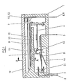
- the monostable delay relay shown schematically as an exemplary embodiment takes the exciter part in a housing 1 with cover 12 made of heat-stable, electrically insulating material in the upper region above an intermediate floor 20 and in the lower region under the intermediate floor the switching part (or load part) on.
- the intermediate floor 20 is used for sufficient electrical isolation, i. H. the sufficient length of clearances and creepage distances between the excitation and switching parts with the smallest possible construction volume.
- the excitation part consists of the heater 11, shown as an individual part in FIG. 4, and a wire 10 known per se made of a special, so-called shape-memory alloy. Due to the crystal structure of its alloy, this wire 10 has the property of contracting when heated by approximately 3% of its original length or expanding again to its original length when cooling, if it is held under low mechanical tensile stress. The rate of heating determines the rate at which the wire contracts.
- the heater 11 as a heat source is designed as a thin, good heat-conducting ceramic plate with a resistance layer 111.
- the electrical resistance of this layer can be produced in any desired values and, together with the operating voltage by heat transfer, determines the contraction speed of the wire 10 and thus the delay time after which the snap switch 2, 3, 4, 5 switches on after the excitation or heating current is switched on. switches off or on.
- the resistance layer 111 is designed in such a way that it increases its electrical resistance value independently as the temperature rises, which advantageously has the effect that overheating of the heater 11 is prevented and the power consumption of the heater 11 is reduced.
- a further advantageous embodiment consists in electrically connecting the resistance layer 111 with a PTC resistor, which is also arranged on the ceramic plate of the heater 11, so that overheating is avoided and the power requirement of the heater 11 is reduced.
- the current supply to the resistance layer takes place from 2 contact surfaces 112, 113 on the edge of the heater 11 via conductor tracks which are printed on the ceramic plate.
- Resiliently designed areas of the two contacts 8, 9 firmly anchored in the housing 1 act on the contact surfaces 112, 113, via which the excitation voltage is supplied to the heater 11 from the outside. Due to the resiliently designed areas of the two contacts 8, 9, the heater 11 can be plugged in and can therefore be easily replaced after the cover 12 has been removed.
- the heater 11 rests on the intermediate floor 20 (see FIG. 2) and forms together with this an elongated chamber through which the wire 10 extends at a short distance from the heater 11, the resistance layer 111 preferably on the side of the wire facing away from the heater Heater 11 is arranged to ensure electrical insulation between the resistance layer 111 and the wire 10.
- the wire 10 made of a shape-memory alloy is anchored at one end in a suitable manner on the housing 1, with the other end attached to a rocker arm 7, which is preferably pivotally mounted in the housing 1.
- a transmission piece 6 made of electrically insulating material is inserted with sufficient rotation so that the pivoting movement of the rocker arm 7 is not hindered.
- the transfer piece 6 acts on the switching part, which works on the principle of a mechanical, monostable flip-flop and whose return spring 41, as part of the spring 4, holds the wire 10 under the required mechanical tension via the transfer piece 6 and the rocker arm 7 and at the same time advantageously all of them Prevents lots in this transmission chain.
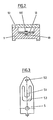
- the switching part consists as a snap switch from the switching spring 5, which is shown in FIG. 3 as a single part and to which the electrical voltage of the load current to be switched is applied from the outside, the spring 4, which is designed with the return spring 41 to form a component and in 5 is shown as an individual part, the normally closed contact 3 with external connection and the changeover contact 2 with external connection.
- the snap switch acts as an electrical changeover switch. If the normally closed contact 3 is removed and replaced by a fixed stop on the housing 1, the snap switch acts as an electrical switch. If the changeover contact 2 is removed and replaced by a stop fixed to the housing, the snap switch acts as an off switch.
- the switching spring 5 in the preferred embodiment according to FIG. 3 consists of a resilient, electrically highly conductive strip material and is fastened in the housing 1 in such a way that the electrical external connection protrudes from the housing 1 on one side and with the contact on the other side 52 - preferably as a contact rivet made of suitable contact material - can swing freely resiliently between the contacts 2 and 3 fixed to the housing.
- This freely resilient part of the switching spring 5 is recessed in such a way that webs remain symmetrical to the center line along the outer edges and a web 51 connected on one side to the contact side 52 remains in the center.
- a U-shaped leaf spring - the spring 4 - is arranged between the web 51 and the edge 53 such that the U-leg of the spring 4 in the region of its leg ends on the web 51 and on the edge 53 of the Switch spring 5 and resiliently spread apart and that preferably the U-leg facing the web 51 carries a bent leaf spring 41, which is preferably supported resiliently on the housing 1.
- the spreading force of the U-legs of the spring 4 causes the outer webs of the switching spring 5 to experience a mechanical tensile stress and the web 51 to experience a mechanical compressive stress.
- the leaf spring 41 causes by the resilient contact with the housing 1 that the spring 4 pivots on the edge 53, so that the web 51 lifts out of the plane of the switching spring 5 and that the compressive stress of the web 51 and the tensile stress of the outer webs of the switching spring 5 Generate a torque that is supported on the contact 52 and generates the required contact force.
- the transfer piece 6 presses against the spring 4, preferably in the region of the root of the U-leg, which faces the clamping point of the switching spring 5. Suitable contours of the individual parts ensure that the position assignments of these individual parts are sufficiently fixed without impeding the pivoting movements, and that simple plug-in assemblies are possible.
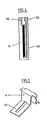
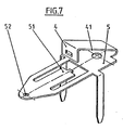
- the switching spring 5 and the spring 4 of FIGS. 1, 3 and 4 are combined into one part - shown in FIG. 7 - and the rocker arm 7 and the transmission piece 6 of FIG. 1 summarized to a redesigned rocker arm in Fig. 6, without changing the principle and sequence of the switching functions.
- the bent tab 4 is bent elastically into the plane of the sheet 5 from resilient, electrically highly conductive strip material, such that the pin on the web 51 comes to rest in the recess on the tab 4.
- the area 41 is bent resiliently.
- the flap 4 exerts a mechanical compressive stress on the web 51 due to its spring-elastic property and, as a result, exerts a mechanical tensile stress on the two outer webs of the level 5, while the area 41, due to its spring property, exerts the web 51 over the web 4 Level 5 highlights.
- the resilient area 41 according to FIG. 6 ensures that it rests on the arm 6 of the rocker arm 7, to which the wire 10 made of a shape-memory alloy is fastened in a suitable manner, and thus ensures sufficient mechanical tension in the wire 10.
Landscapes
- Thermally Actuated Switches (AREA)
- Temperature-Responsive Valves (AREA)
Applications Claiming Priority (2)
| Application Number | Priority Date | Filing Date | Title |
|---|---|---|---|
| DE3842171 | 1988-12-15 | ||
| DE19883842171 DE3842171A1 (de) | 1988-12-15 | 1988-12-15 | Verzoegerungsrelais |
Publications (2)
| Publication Number | Publication Date |
|---|---|
| EP0373544A2 true EP0373544A2 (fr) | 1990-06-20 |
| EP0373544A3 EP0373544A3 (fr) | 1991-09-25 |
Family
ID=6369191
Family Applications (1)
| Application Number | Title | Priority Date | Filing Date |
|---|---|---|---|
| EP19890122747 Withdrawn EP0373544A3 (fr) | 1988-12-15 | 1989-12-09 | Relais à action retardée |
Country Status (2)
| Country | Link |
|---|---|
| EP (1) | EP0373544A3 (fr) |
| DE (1) | DE3842171A1 (fr) |
Cited By (3)
| Publication number | Priority date | Publication date | Assignee | Title |
|---|---|---|---|---|
| EP0538224A1 (fr) * | 1991-10-14 | 1993-04-21 | ELECTROLUX RESEARCH & INNOVATION AB | Relais |
| FR2703184A1 (fr) * | 1993-03-03 | 1994-09-30 | Gen Electric | Contacteur actionné électro-thermiquement. |
| CN111180263A (zh) * | 2020-02-01 | 2020-05-19 | 深圳市星河泉新材料有限公司 | 一种记忆合金部件驱动的保持型继电器 |
Families Citing this family (1)
| Publication number | Priority date | Publication date | Assignee | Title |
|---|---|---|---|---|
| CN110106668B (zh) * | 2019-06-11 | 2021-06-15 | 温州天健电器有限公司 | 电动门锁通断电控制装置、门锁、洗衣机 |
Family Cites Families (14)
| Publication number | Priority date | Publication date | Assignee | Title |
|---|---|---|---|---|
| DE548689C (de) * | 1930-01-25 | 1932-04-16 | Hartmann & Braun Akt Ges | Temperaturregler |
| US3203166A (en) * | 1961-09-08 | 1965-08-31 | Texas Instruments Inc | Thermostatic elements |
| US3174015A (en) * | 1962-06-01 | 1965-03-16 | Tung Sol Electric Inc | Thermoresponsive snap switch having separate ceramic heater means |
| GB1053891A (fr) * | 1963-02-11 | |||
| US3676815A (en) * | 1969-07-28 | 1972-07-11 | Essex International Inc | Thermally sensitive controls for electric circuits |
| US3858141A (en) * | 1973-12-03 | 1974-12-31 | Texas Instruments Inc | Reduced actuation time thermal relay system |
| DE2709175A1 (de) * | 1977-03-03 | 1978-09-07 | Inter Control Koehler Hermann | Thermostat-kombination |
| DE7920923U1 (de) * | 1979-07-21 | 1979-10-25 | Limitor Ag, Zuerich (Schweiz) | Thermischer Zeitschalter |
| CH627876A5 (de) * | 1980-07-08 | 1982-01-29 | Bbc Brown Boveri & Cie | Zeitschalter. |
| DE3223479A1 (de) * | 1982-06-23 | 1983-12-29 | Bosch-Siemens Hausgeräte GmbH, 7000 Stuttgart | Thermostat-schnappfederschalter, insbesondere fuer temperaturregler in backoefen |
| JPS6124965U (ja) * | 1984-07-18 | 1986-02-14 | シャープ株式会社 | 形状記憶合金ばねの接続装置 |
| DE3508248A1 (de) * | 1985-03-08 | 1986-09-11 | E.G.O. Elektro-Geräte Blanc u. Fischer, 7519 Oberderdingen | Elektrische beheizung fuer ein bimetall, insbesondere fuer ein elektrisches leistungssteuergeraet |
| US4684913A (en) * | 1986-09-05 | 1987-08-04 | Raychem Corporation | Slider lifter |
| DE3644514A1 (de) * | 1986-12-24 | 1988-07-07 | Inter Control Koehler Hermann | Bimetallschalter |
-
1988
- 1988-12-15 DE DE19883842171 patent/DE3842171A1/de not_active Ceased
-
1989
- 1989-12-09 EP EP19890122747 patent/EP0373544A3/fr not_active Withdrawn
Cited By (5)
| Publication number | Priority date | Publication date | Assignee | Title |
|---|---|---|---|---|
| EP0538224A1 (fr) * | 1991-10-14 | 1993-04-21 | ELECTROLUX RESEARCH & INNOVATION AB | Relais |
| FR2703184A1 (fr) * | 1993-03-03 | 1994-09-30 | Gen Electric | Contacteur actionné électro-thermiquement. |
| US5510598A (en) * | 1993-03-03 | 1996-04-23 | Martin Marietta Corporation | Electro-thermally actuated switch |
| CN111180263A (zh) * | 2020-02-01 | 2020-05-19 | 深圳市星河泉新材料有限公司 | 一种记忆合金部件驱动的保持型继电器 |
| CN111180263B (zh) * | 2020-02-01 | 2025-09-23 | 深圳市星河泉新材料有限公司 | 一种记忆合金部件驱动的保持型继电器 |
Also Published As
| Publication number | Publication date |
|---|---|
| DE3842171A1 (de) | 1990-06-28 |
| EP0373544A3 (fr) | 1991-09-25 |
Similar Documents
| Publication | Publication Date | Title |
|---|---|---|
| DE69507848T2 (de) | Kompakte Schutzeinrichtung | |
| DE3688800T2 (de) | Schutzsysteme für einen Kältemaschinenkompressormotor. | |
| DE3644514C2 (fr) | ||
| EP0575783B1 (fr) | Pièce électrique | |
| EP0557744A1 (fr) | Interrupteur thermique | |
| EP0994498B1 (fr) | Interrupteur avec support isolant | |
| DE3713922A1 (de) | Stromfuehlertransformator | |
| DE2238341A1 (de) | Thermoempfindlicher schalter | |
| DE69414400T2 (de) | Elektrische schalter | |
| DE2917557C2 (de) | Wärmeschutzschalter | |
| DE19922633A1 (de) | Thermostat | |
| DE7425172U (de) | Verzögert ansprechendes Relais | |
| DE3122758A1 (de) | Betaetigungsschalter | |
| EP0045007B1 (fr) | Plaque de cuisson électrique munie d'un disjoncteur thermique | |
| DE2645663A1 (de) | Vorrichtung zur thermischen betaetigung von schaltern o.dgl. | |
| DE3233909A1 (de) | Schnappvorrichtung, insbesondere elektrischer schnappschalter | |
| EP0058372A1 (fr) | Interrupteur thermique à élément bimétallique | |
| DE3827306A1 (de) | Wasserdichte schalteinrichtung fuer elektrische anlagen | |
| EP0373544A2 (fr) | Relais à action retardée | |
| DE1284515B (de) | Elektrisches Relais | |
| DE1924701A1 (de) | Thermisch ansprechender Schnappschalter | |
| EP0860846A2 (fr) | Régulateur électrique de puissance, en particulier pour appareil à chauffage électrique | |
| EP0951041A2 (fr) | Interrupteur à commande thermique | |
| DE2540499C3 (de) | Temperaturregler für Elektrogeräte mit einer Ausdehnungsdose | |
| DE2422684C3 (de) | Schnappschalter |
Legal Events
| Date | Code | Title | Description |
|---|---|---|---|
| PUAI | Public reference made under article 153(3) epc to a published international application that has entered the european phase |
Free format text: ORIGINAL CODE: 0009012 |
|
| 17P | Request for examination filed |
Effective date: 19891209 |
|
| AK | Designated contracting states |
Kind code of ref document: A2 Designated state(s): AT BE CH DE ES FR GB GR IT LI NL SE |
|
| PUAL | Search report despatched |
Free format text: ORIGINAL CODE: 0009013 |
|
| AK | Designated contracting states |
Kind code of ref document: A3 Designated state(s): AT BE CH DE ES FR GB GR IT LI NL SE |
|
| 17Q | First examination report despatched |
Effective date: 19931116 |
|
| STAA | Information on the status of an ep patent application or granted ep patent |
Free format text: STATUS: THE APPLICATION IS DEEMED TO BE WITHDRAWN |
|
| 18D | Application deemed to be withdrawn |
Effective date: 19940329 |