EP0373642A2 - Ecrou et boulon en matiériau composite - Google Patents
Ecrou et boulon en matiériau composite Download PDFInfo
- Publication number
- EP0373642A2 EP0373642A2 EP89123097A EP89123097A EP0373642A2 EP 0373642 A2 EP0373642 A2 EP 0373642A2 EP 89123097 A EP89123097 A EP 89123097A EP 89123097 A EP89123097 A EP 89123097A EP 0373642 A2 EP0373642 A2 EP 0373642A2
- Authority
- EP
- European Patent Office
- Prior art keywords
- core
- thread
- threaded member
- fabric layer
- reinforcing fabric
- Prior art date
- Legal status (The legal status is an assumption and is not a legal conclusion. Google has not performed a legal analysis and makes no representation as to the accuracy of the status listed.)
- Withdrawn
Links
Images





Classifications
-
- B—PERFORMING OPERATIONS; TRANSPORTING
- B29—WORKING OF PLASTICS; WORKING OF SUBSTANCES IN A PLASTIC STATE IN GENERAL
- B29D—PRODUCING PARTICULAR ARTICLES FROM PLASTICS OR FROM SUBSTANCES IN A PLASTIC STATE
- B29D1/00—Producing articles with screw-threads
- B29D1/005—Producing articles with screw-threads fibre reinforced
-
- B—PERFORMING OPERATIONS; TRANSPORTING
- B29—WORKING OF PLASTICS; WORKING OF SUBSTANCES IN A PLASTIC STATE IN GENERAL
- B29C—SHAPING OR JOINING OF PLASTICS; SHAPING OF MATERIAL IN A PLASTIC STATE, NOT OTHERWISE PROVIDED FOR; AFTER-TREATMENT OF THE SHAPED PRODUCTS, e.g. REPAIRING
- B29C53/00—Shaping by bending, folding, twisting, straightening or flattening; Apparatus therefor
- B29C53/56—Winding and joining, e.g. winding spirally
- B29C53/58—Winding and joining, e.g. winding spirally helically
- B29C53/583—Winding and joining, e.g. winding spirally helically for making tubular articles with particular features
- B29C53/585—Winding and joining, e.g. winding spirally helically for making tubular articles with particular features the cross-section varying along their axis, e.g. tapered, with ribs, or threads, with socket-ends
-
- B—PERFORMING OPERATIONS; TRANSPORTING
- B29—WORKING OF PLASTICS; WORKING OF SUBSTANCES IN A PLASTIC STATE IN GENERAL
- B29C—SHAPING OR JOINING OF PLASTICS; SHAPING OF MATERIAL IN A PLASTIC STATE, NOT OTHERWISE PROVIDED FOR; AFTER-TREATMENT OF THE SHAPED PRODUCTS, e.g. REPAIRING
- B29C70/00—Shaping composites, i.e. plastics material comprising reinforcements, fillers or preformed parts, e.g. inserts
- B29C70/04—Shaping composites, i.e. plastics material comprising reinforcements, fillers or preformed parts, e.g. inserts comprising reinforcements only, e.g. self-reinforcing plastics
- B29C70/06—Fibrous reinforcements only
- B29C70/10—Fibrous reinforcements only characterised by the structure of fibrous reinforcements, e.g. hollow fibres
- B29C70/16—Fibrous reinforcements only characterised by the structure of fibrous reinforcements, e.g. hollow fibres using fibres of substantial or continuous length
- B29C70/22—Fibrous reinforcements only characterised by the structure of fibrous reinforcements, e.g. hollow fibres using fibres of substantial or continuous length oriented in at least two directions forming a two-dimensional [2D] structure
- B29C70/222—Fibrous reinforcements only characterised by the structure of fibrous reinforcements, e.g. hollow fibres using fibres of substantial or continuous length oriented in at least two directions forming a two-dimensional [2D] structure the structure being shaped to form a three dimensional configuration
-
- F—MECHANICAL ENGINEERING; LIGHTING; HEATING; WEAPONS; BLASTING
- F16—ENGINEERING ELEMENTS AND UNITS; GENERAL MEASURES FOR PRODUCING AND MAINTAINING EFFECTIVE FUNCTIONING OF MACHINES OR INSTALLATIONS; THERMAL INSULATION IN GENERAL
- F16B—DEVICES FOR FASTENING OR SECURING CONSTRUCTIONAL ELEMENTS OR MACHINE PARTS TOGETHER, e.g. NAILS, BOLTS, CIRCLIPS, CLAMPS, CLIPS OR WEDGES; JOINTS OR JOINTING
- F16B33/00—Features common to bolt and nut
- F16B33/006—Non-metallic fasteners using screw-thread
-
- B—PERFORMING OPERATIONS; TRANSPORTING
- B29—WORKING OF PLASTICS; WORKING OF SUBSTANCES IN A PLASTIC STATE IN GENERAL
- B29K—INDEXING SCHEME ASSOCIATED WITH SUBCLASSES B29B, B29C OR B29D, RELATING TO MOULDING MATERIALS OR TO MATERIALS FOR MOULDS, REINFORCEMENTS, FILLERS OR PREFORMED PARTS, e.g. INSERTS
- B29K2105/00—Condition, form or state of moulded material or of the material to be shaped
- B29K2105/06—Condition, form or state of moulded material or of the material to be shaped containing reinforcements, fillers or inserts
- B29K2105/08—Condition, form or state of moulded material or of the material to be shaped containing reinforcements, fillers or inserts of continuous length, e.g. cords, rovings, mats, fabrics, strands or yarns
- B29K2105/0809—Fabrics
- B29K2105/0827—Braided fabrics
-
- F—MECHANICAL ENGINEERING; LIGHTING; HEATING; WEAPONS; BLASTING
- F16—ENGINEERING ELEMENTS AND UNITS; GENERAL MEASURES FOR PRODUCING AND MAINTAINING EFFECTIVE FUNCTIONING OF MACHINES OR INSTALLATIONS; THERMAL INSULATION IN GENERAL
- F16B—DEVICES FOR FASTENING OR SECURING CONSTRUCTIONAL ELEMENTS OR MACHINE PARTS TOGETHER, e.g. NAILS, BOLTS, CIRCLIPS, CLAMPS, CLIPS OR WEDGES; JOINTS OR JOINTING
- F16B35/00—Screw-bolts; Stay-bolts; Screw-threaded studs; Screws; Set screws
-
- F—MECHANICAL ENGINEERING; LIGHTING; HEATING; WEAPONS; BLASTING
- F16—ENGINEERING ELEMENTS AND UNITS; GENERAL MEASURES FOR PRODUCING AND MAINTAINING EFFECTIVE FUNCTIONING OF MACHINES OR INSTALLATIONS; THERMAL INSULATION IN GENERAL
- F16B—DEVICES FOR FASTENING OR SECURING CONSTRUCTIONAL ELEMENTS OR MACHINE PARTS TOGETHER, e.g. NAILS, BOLTS, CIRCLIPS, CLAMPS, CLIPS OR WEDGES; JOINTS OR JOINTING
- F16B37/00—Nuts or like thread-engaging members
-
- Y—GENERAL TAGGING OF NEW TECHNOLOGICAL DEVELOPMENTS; GENERAL TAGGING OF CROSS-SECTIONAL TECHNOLOGIES SPANNING OVER SEVERAL SECTIONS OF THE IPC; TECHNICAL SUBJECTS COVERED BY FORMER USPC CROSS-REFERENCE ART COLLECTIONS [XRACs] AND DIGESTS
- Y10—TECHNICAL SUBJECTS COVERED BY FORMER USPC
- Y10S—TECHNICAL SUBJECTS COVERED BY FORMER USPC CROSS-REFERENCE ART COLLECTIONS [XRACs] AND DIGESTS
- Y10S411/00—Expanded, threaded, driven, headed, tool-deformed, or locked-threaded fastener
- Y10S411/90—Fastener or fastener element composed of plural different materials
- Y10S411/901—Core and exterior of different materials
-
- Y—GENERAL TAGGING OF NEW TECHNOLOGICAL DEVELOPMENTS; GENERAL TAGGING OF CROSS-SECTIONAL TECHNOLOGIES SPANNING OVER SEVERAL SECTIONS OF THE IPC; TECHNICAL SUBJECTS COVERED BY FORMER USPC CROSS-REFERENCE ART COLLECTIONS [XRACs] AND DIGESTS
- Y10—TECHNICAL SUBJECTS COVERED BY FORMER USPC
- Y10S—TECHNICAL SUBJECTS COVERED BY FORMER USPC CROSS-REFERENCE ART COLLECTIONS [XRACs] AND DIGESTS
- Y10S411/00—Expanded, threaded, driven, headed, tool-deformed, or locked-threaded fastener
- Y10S411/904—Fastener or fastener element composed of nonmetallic material
- Y10S411/908—Resinous material
Definitions
- This invention relates to reinforced threaded plastic members such as nuts and bolts, and more particularly threaded composite members which are reinforced with fibers extending in multiple directions and to methods of making same.
- U.S. Patent 3,495,494 to A.L. Scott discloses a threaded plastic member having a glass fiber reinforced thread in which a plurality of resin impregnated glass fiber reinforcing filaments are disposed in serpentine manner throughout the cross section of the thread and extending longitudinally of the axis of the threaded member.
- Manufacture of the threaded member requires a precision mold having a cavity complementary to that of the member to be formed.
- nuts may be formed by curing a plurality of resin-impregnated filaments laid axially about a rod having complementary threads and thereafter unscrewing the rod from the molding and cutting the molding into a plurality of nuts. To form the head on a bolt, one of these nuts is screwed onto one end of the shank molding and cemented into place.
- U.S. Patent 4,478,544 to Strand discloses a reinforced plastic rivet formed of carbon fibers encapsulated in an incompletely polymerized thermoset resin matrix. To use the rivet, its head portion is heated to soften the resin, the head is upset and fully polymerized. As with all rivets, this one is not threaded.
- This rivet has the further disadvantage of needing to be stored in a controlled low temperature environment prior to use to prevent premature setting of the resin.
- U.S. Patent 2,306,516 to Zahn discloses the use of a parting medium or membrane, such as rubber, over a threaded fastener which functions as a pattern to manufacture a hollow casting mold.
- U.S. Patent 4,389,269 to Cooper et al discloses a sport racket frame construction and a method of making same. A resin-impregnated tow is wound about part of a braided tow tube and thereafter a second braided tow tube is placed thereon to form an assembly that is internally pressurized and heat cured.
- U.S. Patent 4,265,981 to Campbell discloses impact resisting composites which may comprise multiple parallel filaments helically wrapped by continuous multiple filaments or strips and embedded in a matrix material.
- a method of making a hollow composite internally threaded member comprising: providing an elongate externally threaded cylindrical core, which is treated with a release agent; forming on the core a reinforcing fabric layer enveloping the core and conforming to the threads of the core; embedding the reinforcing fabric layer in a polymeric matrix.
- a hollow internally threaded member formed of fibers in a polymer matrix, said member having an interior surface having an integral thread having a rounded apex, said thread including a reinforcing fabric layer extending in the axial direction of the member and conforming to the threads.
- a hollow internally threaded member formed of fibers in a polymeric matrix, said member having an interior surface having an integral thread having a rounded apex, said thread including a reinforcing fabric layer extending in the axial direction of the member and conforming to the threads, said hollow internally threaded member being threadedly joined to an externally threaded member of complementary thread pitch and thread diameter, said externally threaded member comprising an elongate core and an integral tubular layer of textile fabric bonded to the exterior surface of the core, said integral textile layer being selected from one of continuous woven, continuous knit or continuous braided textile material, the textile layer enveloping, conforming and bonded with polymeric matrix to the exterior of the polymeric core.
- the elongate externally threaded cylindrical core may be solid or hollow.
- the elongate threaded cylindrical core may itself be a composite member.
- the core may contain a helical thread defining element which contains a fibrous reinforcement or may be defined by a bundle of filaments, a braided or twisted cord or a polymeric matrix alone or in combination with one of the foregoing.
- the core may include a braided layer thereon in which at least one element of greater radial projection relative to the core than the remainder of the elements forming the braided layer is included, the element of greater radial projection defining a helical thread on the core.
- the reinforcing fabric layer of the hollow internally threaded member may be braided or knit. Heat and pressure may be applied subsequent to formation of the reinforcing fabric layer to effect consolidation of the fabric layer and associated polymeric matrix with the underlying threaded core. Provision of a release coating on the core prior to formation of the hollow internally threaded member enables separation of the completed internally threaded member from the core on which it is formed. No mold is required external of the internally threaded member. The assembly upon the previously formed threaded core may be completed by curing/consolidating the fabric reinforced matrix internal threaded member upon the molding core in an autoclave.
- the terms having, including, comprising and containing are synonymous. Unless otherwise specified at the point of use, all percentages, fractions and ratios in this specification, including the claims appended thereto, are on a weight basis.
- the term “rod” as used herein means a slender bar and may be hollow or solid.
- the term “pitch” and related forms as used herein means the distance from any point on the helical thread of a thread member to the corresponding point on the adjacent thread formed by that same helical member measured parallel to the longitudinal axis of the threaded member.
- the term “helix angle” as used herein means the acute angle formed by the path of a thread-defining helical element and the axial or lengthwise direction of the threaded member. A higher helix angle corresponds to a smaller pitch for threaded members of equal diameter and thread defining element radial projection.
- like numbers are used to refer to like features or members.
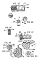
- Hollow internally threaded member 110 is formed of a fiber-reinforced polymeric matrix.
- the interior surface of threaded member 110 includes an integral thread having a rounded apex.
- the thread includes a reinforcing fabric layer which extends in the axial direction of internally threaded member 110 and conforms to the contour of the internal thread thereof.
- FIG 2d there is shown an internally threaded member like that shown in Figure 2c, the difference being that the member 111 has been sliced from a greater axial length element such as member 110.
- the exterior axially extending surfaces of members 110 and 111 are cylindrical.
- Figure 2e shows a hexagonal internally threaded member or nut 112 which in other respects is like members 110 and 111.
- the interior surface 125 in member 110, 111, 112 includes a helical thread 126 extending in its lengthwise or axial direction.
- the reinforcing fabric layer is undulate and conforms to and extends throughout the contour of the threaded interior surface 125 of member 110, 111, 112.
- the reinforcing fabric layer is preferably a continuous tubular fabric layer formed in the manner shown in Figure 2b by braiding or knitting suitable high modulus textile fibers. Preferred are fibers of high Young's modulus such as those of aramid, glass and carbon.
- FIGs 2f and 2g there is shown a composite bolt 120 according to the present invention which has been formed by threadedly joining a internally threaded member such as nut 112 to a separately formed externally threaded composite member 121 which may have been formed in the manner hereinafter described for externally threaded members 10, 50, 210, 250.
- Nut 112 is threaded on to threaded shank 121 and is bonded with adhesive 122 to prevent further rotation of nut 112 relative to shank 121. Bonding is accomplished with polymeric material such as epoxy or other matrix which is compatible with the matrices of nut 112 and shank 121.
- FIG 1 there is shown a manner of manufacture according to the invention of an internally threaded member according to the present invention.
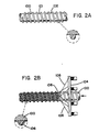
- An externally threaded cylindrical core such as core 100 depicted in Figure 2a is used as a carrier and mold for formation of an internally threaded member such as member 110 depicted in Figure 2c.
- Core 100 must include an exterior surface 101 which will not bond to the internally threaded member to be formed except where it is desired to form directly a threaded bolt or the like such as that depicted in Figure 2f.
- the externally threaded cylindrical core 100 is surface treated with release agent 102 as shown in Figure 1 and Figure 2a.
- reinforcing fabric layers are formed on core 100. This is preferably accomplished as shown in Figure 2b by passing core 100 through a tubular braiding or knitting machine or succession of such machines. Braiding or knitting machine 104 is provided with a plurality of carriers each letting off a continuous tow of fibrous material 105 which is laid up into a tubular reinforcing fabric layer 106 on core 100.
- the reinforcing fabric layer 106 envelopes and conforms to the contours defined by the helical threads of the outer surface 101 of core 100.
- the reinforcing fabric layer 106 is multidirectional in character; it has fibrous elements which extend at differing angles relative to the axial direcion of the internally threaded member being formed, at least some of the fibrous elements extending generally in the same direction as the helical threads and others of the fibrous elements extending generally in a direction opposite to that of the helical threads.
- the internal thread of the hollow member is reinforced with closely spaced fibers which extend axially of the member in opposite sense helices.
- a sheath or covering of polymeric matrix is applied to the combined externally threaded core and fabric layer 106.
- Polymeric material may be precoated onto the fibrous material 105.
- Such fibrous material 105 may alternatively be impregnated with polymeric material prior to or subsequent to conversion into fabric layer 106 on the core 100.
- a plurality of reinforcing fabric layers may be sequentially formed each upon the preceding underlying reinforcing fabric layer.
- Polymeric matrix material may be applied between application of each successive reinforcing fabric layer.
- polymeric material may be applied subsequent to application of all of the reinforcing fabric layers such as by pressure impregnation.
- the polymeric material if a liquid, must be of sufficient viscosity to remain with the fibrous material and not drip off the combined internally threaded member being manufactured and its underlying core.
- the core and internally threaded member being manufactured may be rotated about the horizontally oriented longitudinal axis of the core 100.
- the assembly is preferably subjected to heat and pressure to consolidate and bond the polymeric matrix and the fabric layers into a unitary, stable, internally threaded composite member such as member 110 shown in Figure 2c.
- This may be conveniently accomplished in an ordinary autoclave when thermosettable polymeric resins are employed. Autoclaving may also be employed with thermoplastic polymeric resins. No external mold is required.
- the combined internally threaded member and its core are removed from the autoclave, thereafter the newly formed internally threaded member 110 is removed from core 100 by rotating member 110 relative to core 100.
- core 100 has been partially withdrawn from the right hand portion of internally threaded member 110.
- the previously applied release agent 101 facilitates separation of internally threaded member 110 from core 100.
- internally threaded member 110 is made of sufficient axial length such that it may be cut into a plurality of smaller internally threaded members such as internally threaded member 111 shown in Figure 2d.
- the exterior cylindrical surface 127 of member 111 may be machined to form a hexagonal outer surface 128 such as that shown for member 112 in Figures 2e, 2f and 2g.
- Hex nut 112 includes a continuous helical thread 126 extending in the axial direction of nut 112 within its central aperture.
- Internal helical thread 126 is reinforced by reinforcing fabric layer 106 which conforms to the contour defined by external helical thread of core 100.
- nut 112 includes a plurality of coaxial fabric reinforcing layers 129 distributed throughout its cross-sectional area.
- Nut 112 may be threadedly joined to an externally threaded composite member such as shank 121 shown in Figure 2f and Figure 2g. Nut 112 is bonded to shank 121 with polymeric material 122 such as an epoxy adhesive to form composite bolt 120.
- an optional process for formation of items such as bolt 120 depicted in Figures 2f and 2g includes only B-staging the internally and externally threaded members such as the nut and shank prior to threadedly joining them and thereafter applying heat and pressure to consolidate the internally threaded member to the shank and effect a chemical bond therebetween.
- the resin and fabric materials for nut 112 and shank 121 is based primarily on intended end use according to the in-service properties required for the intended application. In low temperature and low stress applications, it is adequate to utilize a shank formed of extruded thermoplastic such as, by way of example and without limitation, nylon. Where greater strength is desired or necessary, the polymer matrix may be filled with discontinuous or continuous fibers. Crystalline polymers are generally more resistant to creep than non-crystalline polymers. Where greatest strength and resistance to creep are desired, the core is preferably formed of thermosettable polymeric matrix which is reinforced with continuous fibers which extend in the axial, that is the lengthwise direction of shank 121.
- Suitable resins include, by way of example and without limitation, nylons (polyamides), polyesters, polyolefins, polyaroline sulfides (pps), epoxies, polyimides, and the like.
- Suitable fibers include, by way of example and without limitation, glass, aramid, ceramic fibers and whiskers, and carbon fibers, and the like, including combinations thereof.
- the fibers of the nut and shank should have a Young's modulus greater than that of the polymeric matrix in which they are embedded.
- a particularly suitable shank for applications where high modulus and strength and temperature are desired is a rod formed of glass fiber or carbon fiber in a polyphenylene sulfide matrix which rods are available under the trademark RYTON PPS from Phillips Petroleum Company, Bartlesville, Oklahoma.
- fibers of high Young's modulus such as those of aramid, glass and carbon.
- the fibers may be treated to enhance adhesion to the polymeric resin. Such treatment is not within the scope of the present invention but is well known to those skilled in the manufacture of fibers for reinforcement of composites.
- the fibrous material tow 105 which is utilized to form the reinforcing fabric layer 106 may itself be formed of a plurality of sub-elements such as filaments of generally rounded cross-sectional configuration.
- the filaments may be incapsulated with polymeric matrix.
- the filaments may be twisted together into a yarn.
- a plurality of may be twisted into a cord.
- a plurality of cords may be twisted to form a larger continuous fibrous material element.
- Fibrous material 105 may be of flattened or rounded cross-sectional configuration and may be twisted or untwisted or braided.
- either fibrous material tows 105 are impregnated prior to forming into reinforcing fabric layer 106 or are laid onto a previously applied layer of polymeric material, preferably liquid polymeric material which wets the fibers and encapsulates them.
- the internal threads of female member 110 and those derived therefrom are reinforced against rupture. Due to the multi-directional character of the filaments of the reinforcing fabric layer, at least some of the filaments of the textile reinforcing material are oriented in planes at a considerable angle to the plane of the shearing forces acting on the internal threads of member 110.
- Resins which set by chemical action alone without application of heat may also be employed.
- the resin employed in the manufacture of the internally threaded member such as nut 112 which is to be joined with a composite shank such as 121 to form a bolt or capscrew 120 is selected so as to be compatible with the resin employed in the manufacture of such shank.
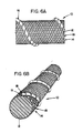
- Threaded member 10 includes an elongate core 12 and a tubular braided layer 14 which is bonded to the exterior surface of the core 12. In certain preferred embodiments braided layer 14 is embedded in a matrix (not shown). Braided layer 14 includes a thread-defining element 16 which extends in helical fashion around and along the exterior cylindrical surface of core 12. Thread-defining element 16 is also an integral part of tubular braided layer 14. Thread-defining element 16 as individually illustrated in Figure 3 is of greater radial projection than that of the other non thread-defining elements 18, one of which is illustrated in Figure 4, which form together with element 16 the tubular braided layer 14.
- the helix angle of the thread(s) varies directly with the size of the core.
- the helix angle of the thread-defining element varies inversely with the size of the thread-defining element.
- Helix angle of the thread-defining element(s) will generally range between 50 and slightly less than 90 degress. The helix angle selected will be based on the materials employed in the manufacture of the fastener, the packing density of the fastener and the design requirements of the intended application for the fastener.
- the core 12 is a rod and is preferably cylindrical although other cross-sectional configurations may be used such as hexagonal and those polygons having a greater number of sides or oval.
- the core 12 may be solid as illustrated in Figures 5, 6 and 8 or hollow as illustrated in Figure 11 by reference numeral 12 ⁇ . Selection of the core is based primarily on intended end use according to the in-service properties required for such application. In low temperature and low stress applications, it is adequate to utilize a core formed of extruded thermoplastic such as, by way of example and without limitation, nylon. Where greater strength is desired or necessary, the polymer matrix may be filled with discontinuous or continuous fibers. Crystalline polymers are generally more resistant to creep than non-crystalline polymers.
- the core is preferably formed of a thermosettable polymeric matrix which is reinforced with continuous fibers which extend in the axial, that is, the lengthwise direction of the core.
- Suitable resins include, by way of example and without limitation, nylons (polyamides), polyesters, polyolefins, polyarylene sulfides (PPS), epoxies, polyimides, and the like.
- Suitable fibers include, by way of example and without limitation, glass, aramid, ceramic fibers and whiskers, and carbon fibers, and the like including combinations thereof.
- the fibers of the core should have a Young's modulus greater than that of the polymeric matrix in which they are embedded.
- a particularly suitable core for applications where high modulus and strength and temperature are desired is a rod formed of glass fiber or carbon fiber in a polyphenylene sulfide matrix, which rods are available under the trademark Rytone PPS from Phillips Petroleum Company, Bartlesville, Oklahoma.
- Thread-defining element 16 may be formed of any suitable fiber including those listed above in regard to the core 12. Preferred are fibers of high Young's modulus such as those of aramid, glass and carbon. The fibers may be treated to enhance adhesion to the polymeric resin. Such treatment is not within the scope of the present invention but is well known to those skilled in the manufacture of fibers for reinforcement of composites.
- the thread-defining element 16 may itself be formed of a plurality of sub-elements 17 such as filaments of generally rounded cross-sectional configuration.
- the filaments 17 may be encapsulated with polymeric matrix 15.
- the filaments 17 may be twisted together into a yarn.
- a plurality of yarns may be twisted into a cord.
- a plurality of cords may be twisted to form a larger thread-defining element.
- a plurality of bundles of filaments or a plurality of yarns or a plurality of cords may themselves be braided to form a thread-defining element.
- a strip of material may be twisted to form thread-defining element 16 or sub-element 17.
- the thread-defining element 16 should be resistant to deformation from its rounded cross-sectional configuration to ensure that element 16 projects radially outwardly from core 12 an amount greater than the remainder of the elements 18 of the braided layer 14.
- element 16 is of circular cross-sectional configuration and resistant to deformation from such cross-sectional configuration as it is braided onto core 12. This may be achieved by forming element 16 of tightly compacted fibers and/or pre-impregnating the sub-elements 17 with a polymeric resin to form a solid circular bundle.
- the non thread-defining elements 18 of braided layer 14 are preferably of flattened cross-sectional configuration.
- the non-thread-defining elements 18 may be formed of any suitable fiber twisted or untwisted, formed into yarn or cord or braided into a flattened strip.
- the non-thread-defining elements may be impregnated in polymeric resin prior to forming braided layer 14.
- a plurality of filamentary parts sub-parts 19 are positioned side-by-side in non-thread-defining element 18.
- Threaded member 50 differs from that depicted in Figure 1 in that it includes a plurality of thread-defining elements 16, each of which extends helically along core 12. Threaded member 50 retains a significant portion of its holding power in the event that one or more of its thread-defining elements 16 are damaged or broken. While four thread-defining elements 16 are illustrated, a greater or lesser number could be employed.
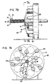
- a portion of the manufacturing process for the present externally threaded members is illustrated in Figures 7A and 7B.
- a conventional tubular braiding apparatus 20 contains a desired number of yarn or cord carriers in its deck 21.
- the number of carriers is not critical.
- the number of carriers needed for complete coverage of the surface of the core increases with the size of the core in a manner well known to those skilled in the art of tubular braiding.
- For fasteners of up to about 1" (2.54 cm) diameter commonly available 24 to 36 unit single deck braiding machines may be employed to obtain full coverage of the core 12 with braided layer 14.
- one or more selected carriers 22 are fitted with a spool of thread-defining element 16, one being shown in Figures 2A and B for simplicity of illustration.
- the remainder of the carriers 23 are fitted with spools of non thread-defining element 18, like those shown in Figure 4.
- the reinforcements 16 and 18 are braided on to the core.
- the thread-defining element 16 is secured to core 12 by a plurality of non thread-defining elements 18 which envelop the core 12 in an opposite sense helical pattern from that of thread-defining element 16.
- thread-defining element 16 is at some points overlapped by non thread-defining elements 18 and at other points non thread-defining elements 18 pass between thread-defining elements 16 and the core 12.
- the thread(s) of the externally threaded composite member are reinforced with fibers which extend across the direction of the thread(s) as well as with fibers which extend in the direction of the thread(s).
- the outer cylindrical surface of core 12 may be coated with or formed of a thermoplastic or thermosettable polymer.
- the surface of the core may be heated to promote embedment and bonding of elements 16 and 18 to the core.
- a liquid bonding polymeric resin may be applied to the core prior to or subsequent to the core being passed through the braider.
- the thread-defining element(s) 16 and non-thread-defining elements 18 are impregnated with resin. In other preferred embodiments elements 16 and 18 are coated with resin.
- the elements of the braided layer are arranged in the tubular braided layer such that the braided layer is stable against rotation when a tensile load is applied in the lengthwise direction of the core. In other words, a torque is not generated when a tensile load is so applied.
- the composite member may be consolidated by application of heat and pressure, for example, in an autoclave.
- additional resin is applied subsequent to braiding to coat and protect the braided layer against abrasion and to promote bonding of the braided layer to the core.
- a distinct abrasion resistant layer of resin may be applied subsequent to banding of the braided layer.
- Resins which set by chemical action alone without application of heat may also be employed.
- the resins employed in the manufacture of the core, impregnation of the thread-defining elements, the non-thread-defining elements, and bonding and coating of the braided layer are selected so as to be compatible with one another.
- Threaded member 210 includes an elongate core 12, a thread-defining element 214 which extends in helical fashion around and along the exterior cylindrical surface of core 12 and a reinforcing fabric layer such as braided layer 215 which envelops, conforms to and is bonded to the outer surface of the combined core 12 and thread-defining element 214.
- Thread-defining element 214 is of greater radial projection than that of the other non-thread-defining elements such as flat bundle braiding elements 216, which are formed into tubular braided fabric layer 215.
- the thread-defining element 214 is integral with or bonded to the core 12.
- thread-defining element is as shown and described in reference to Figure 3.
- Flat bundle braiding elements 216 may be as shown and described in reference to Figure 4.
- the core may include a layer of braided or knit fabric or at least two layers of opposite sense helical fibrous reinforcements to render the core resistant to torsional loading or fibrous reinforcements which extend in lengthwise, that is, the axial direction of the core.
- Thread-defining element 214, 214 ⁇ may be formed of any suitable fiber including those listed above in regard to the cores 12 and 12 ⁇ .
- Preferred are fibers of high Young's modulus such as those of aramid, glass and carbon.
- the fibers may be treated to enhance adhesion to the polymeric resin. Such treatment is not within the scope of the present invention but is well known to those skilled in the manufacture of fibers for reinforcement of composites.
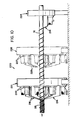
- the thread-defining element 214 may be integrally formed with core 12 or may be helically applied to core 12 by a spiral wrapping machine 224 as shown in Figure 10.
- Thread-defining element 12 may be polymer alone, fiber alone or a combination of polymer and fiber.
- Thread-defining element may be short fibers or continuous fibers in a polymer matrix.
- the thread-defining element 214 may itself be formed of a plurality of sub-elements such as filaments of generally rounded cross-sectional configuration.
- the filaments may be encapsulated with polymeric matrix.
- the filaments may be twisted together into a yarn.
- a plurality of yarns may be twisted into a cord.
- a plurality of cords may be twisted to form a larger thread-defining element.
- a plurality of bundles of filaments or a plurality of yarns or a plurality of cords may themselves be braided to form a thread-defining element.
- a strip of material may be twisted to form thread-defining element or sub-element.
- the thread-defining element 214 should be resistant to deformation from its rounded cross-sectional configuration to ensure that element 214 projects radially outwardly from core 12 and influences the contour of the fabric layer formed thereover.
- element 214 is of circular cross-sectional configuration and resistant to deformation from such cross-sectional configuration as it is spirally wrapped onto core 12. In certain preferred embodiments this is achieved by forming element 214 of tightly compacted fibers and/or pre-impregnating the sub-elements 17 with a polymeric resin 15 to form a solid circular bundle.
- the flat bundle braiding elements 216 of braided fabric layer 215 are preferably of flattened cross-sectional configuration. These flat bundle elements 216 may be as shown and described with reference to Figure 4.
- Threaded member 250 differs from that depicted in Figures 8A and 8B in that it includes a plurality of thread-defining elements 214 ⁇ , each of which extends helically along hollow core 12 ⁇ . Threaded member 250 retains a significant portion of its holding power in the event that one or more of its thread-defining elements 214 ⁇ are damaged or broken. While four thread-defining elements 214 ⁇ are illustrated, a greater or lesser number could be employed. Each of thread-defining elements 214 ⁇ is formed of short fibers in a polymer matrix.
- Apparatus 220 contains in functional sequence a spiral wrap machine 224 and a fabric layer forming machine such as braider deck 221 shown in solid lines or knitting machine 226 shown in dashed lines.
- Braider deck 221 is conventional and includes a desired number of yarn or cord carriers 222. The number of carriers is not critical. The number of carriers needed for complete coverage of the surface of the core 12 increases with the size of the core in a manner well known to those skilled in the art of tubular braiding. For fasteners of up to about 1" (2.54 cm) diameter, commonly available 24 to 36 carrier single deck braiding machines may be employed to obtain full coverage of the core 12 with braided layer 214.
- Each of carriers 222 is fitted with a spool of continuous non-thread-defining element, such as flat bundle element 216 like those shown in Figure 8A.
- thread-defining helical element 214 is spirally wrapped onto the core 12 by spiral wrap machine 224 and thereafter a reinforcing fabric layer 215 is formed by braider deck 221 which braids the braiding elements 216 on to the spiral wrapped core.
- the thread-defining element 214 is bonded to the core 12 with polymeric resin.
- the thread-defining element 214 is also secured to core 12 by a plurality of non-thread-defining elements 216 which envelop the combined core 12 and helically extending thread-defining element 214 in the same and in opposite sense helical patterns from that of thread-defining element 214.
- Thread-defining element 214 is overlapped by non-thread-defining elements 216 of fabric layer 215.
- Fabric layer 215 closely conforms to and follows the outer surface contours of the combined core 12 and thread-defining helical element 214.
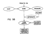
- Figure 9 schematically depicts processes for manufacture of composite threaded members according to the present invention.
- the core as previously discussed, may or may not include a helical thread-defining element at the start of the process. If no helical thread-defining element is present on the core, one is applied for example and without limitation by spiral wrapping or extrusion.
- the thread-defining element may be formed of polymer material alone, fibrous material alone or a combination of polymer and fibrous materials.
- the thread-defining element may be polymer resin coated or impregnated prior to and/or subsequent to its application to the core.
- the outer cylindrical surface of core may be coated with or formed of a thermoplastic or thermosettable polymer.
- the surface of the core may be heated to promote embedding and bonding of the helical thread-defining element and fabric layer to the core.
- a liquid bonding polymeric resin may be applied to the core prior to or subsequent to the core being passed through the spiral wrap machine and the fabric layer forming apparatus.
- Over the combined core and thread-defining helically extending element there is formed a layer of reinforcing fabric, preferably by braiding or knitting. Fibrous material used in forming the reinforcing fabric layer may be coated or impregnated with polymer prior to use to aid in bonding the fibrous material to the combined core and thread-defining element.
- the combined core, thread-defining element and fabric layer are secured to one another, preferably by chemical bonding.
- the fibrous elements forming the reinforcing fabric layer are arranged in the tubular fabric layer such that the fabric layer is stable against rotation when a tensile load is applied in the lengthwise direction of the core. In other words, a torque is not generated which tends to rotate the core when a tensile load is so applied.
- the composite member may be consolidated by application of heat and pressure, for example, in an autoclave.
- This consolidation step forces the reinforcing fabric to more closely conform to the contours defined by the underlying combined core and thread-defining element.
- additional polymeric resin is applied subsequent to formation of the fabric layer to form a sheath which coats and protects the underlying structure layer against abrasion and to promote bonding of the braided layer to the core.
- Multiple applications of polymer resin may be employed to build up a protective sheath.
- a distinctly different resin selected primarily for its abrasion resistance may be applied subsequent to bonding of the reinforcing fabric layer.
- Polymer resins which set by chemical action at room temperature without application of heat may be employed.
- the polymeric resins employed in the manufacture of the core, manufacture and impregnation of the thread-defining elements, the fibrous material used in forming the reinforcing fabric layer, and impregnating, bonding and coating of the fabric layer are selected so as to be compatible with one another.
Landscapes
- Engineering & Computer Science (AREA)
- Mechanical Engineering (AREA)
- Textile Engineering (AREA)
- General Engineering & Computer Science (AREA)
- Chemical & Material Sciences (AREA)
- Composite Materials (AREA)
- Moulding By Coating Moulds (AREA)
- Knitting Of Fabric (AREA)
Applications Claiming Priority (2)
| Application Number | Priority Date | Filing Date | Title |
|---|---|---|---|
| US285483 | 1988-12-16 | ||
| US07/285,483 US5033925A (en) | 1988-12-16 | 1988-12-16 | Composite nut and bolt |
Publications (2)
| Publication Number | Publication Date |
|---|---|
| EP0373642A2 true EP0373642A2 (fr) | 1990-06-20 |
| EP0373642A3 EP0373642A3 (fr) | 1992-01-29 |
Family
ID=23094437
Family Applications (1)
| Application Number | Title | Priority Date | Filing Date |
|---|---|---|---|
| EP19890123097 Withdrawn EP0373642A3 (fr) | 1988-12-16 | 1989-12-14 | Ecrou et boulon en matiériau composite |
Country Status (4)
| Country | Link |
|---|---|
| US (1) | US5033925A (fr) |
| EP (1) | EP0373642A3 (fr) |
| JP (1) | JPH02225028A (fr) |
| CA (1) | CA2005565A1 (fr) |
Cited By (3)
| Publication number | Priority date | Publication date | Assignee | Title |
|---|---|---|---|---|
| RU2317892C1 (ru) * | 2006-06-27 | 2008-02-27 | Общество с ограниченной ответственностью "Компания "Армопроект" | Композитный соединительный элемент с интегральной внутренней резьбой |
| WO2009038925A1 (fr) * | 2007-09-17 | 2009-03-26 | The Boeing Company | Procédé de renforcement de structures composites |
| GB2569295A (en) * | 2017-12-08 | 2019-06-19 | Vestas Wind Sys As | A replacement insert for repair of a joint connecting a wind turbine rotor blade to a rotor hub |
Families Citing this family (18)
| Publication number | Priority date | Publication date | Assignee | Title |
|---|---|---|---|---|
| JP2792716B2 (ja) * | 1990-06-04 | 1998-09-03 | 北川工業株式会社 | 緊締具 |
| US5186500A (en) * | 1990-10-09 | 1993-02-16 | Ameron, Inc. | Fiberglass tubular coupling with liner |
| US5672036A (en) * | 1992-05-22 | 1997-09-30 | Unimation, Inc. | Weldable plastic fastener |
| FR2692633B1 (fr) * | 1992-06-17 | 1995-08-25 | Aerospatiale | Visserie en materiau composite constitue d'une matrice ceramique renforcee de fibres refractaires. |
| US5417529A (en) * | 1993-04-08 | 1995-05-23 | Volkmann; Josef F. | Aerospace fastener with improved bonding |
| NO943718D0 (no) * | 1994-10-05 | 1994-10-05 | Nodeco As | Overlastsikring |
| US5725704A (en) * | 1995-12-21 | 1998-03-10 | Davidson Textron, Inc. | Process for the production of a multi-layer composite article having fasteners affixed to a surface thereof and the article produced thereby |
| US5860779A (en) * | 1997-11-26 | 1999-01-19 | Mcdonnell Douglas Corporation | Locking nut |
| US20050200136A1 (en) * | 2001-02-15 | 2005-09-15 | Integral Technologies, Inc. | Low cost hardware manufactured from conductive loaded resin-based materials |
| US20050200041A1 (en) * | 2001-02-15 | 2005-09-15 | Integral Technologies, Inc. | Low cost hardware manufactured from conductive loaded resin-based materials |
| WO2005116379A2 (fr) * | 2004-05-06 | 2005-12-08 | Integral Technologies, Inc. | Materiel bon marche fabrique a partir de matieres a base de resine chargees conductrices |
| US20060226406A1 (en) * | 2005-04-02 | 2006-10-12 | Alabama Metal Industries Corporation | Non-conductive fencing |
| US7966711B2 (en) * | 2007-08-14 | 2011-06-28 | The Boeing Company | Method and apparatus for fastening components using a composite two-piece fastening system |
| US8393068B2 (en) | 2007-11-06 | 2013-03-12 | The Boeing Company | Method and apparatus for assembling composite structures |
| US8613580B2 (en) * | 2011-04-28 | 2013-12-24 | Lockheed Martin Corporation | Fastening device |
| US10792689B2 (en) | 2014-09-18 | 2020-10-06 | Nylok Llc | Combined spray and vacuum nozzle |
| JP7236725B2 (ja) * | 2018-01-11 | 2023-03-10 | 株式会社タカイコーポレーション | 繊維強化樹脂製ボルト製造方法及び繊維強化樹脂製ボルト |
| CN112794718B (zh) * | 2021-01-27 | 2022-11-04 | 巩义市泛锐熠辉复合材料有限公司 | 一种陶瓷基复合材料螺柱及其制备方法 |
Family Cites Families (25)
| Publication number | Priority date | Publication date | Assignee | Title |
|---|---|---|---|---|
| GB1047205A (fr) * | 1900-01-01 | |||
| US2306516A (en) * | 1941-09-27 | 1942-12-29 | Austenal Lab Inc | Method of making hollow casting molds |
| US2751237A (en) * | 1952-11-10 | 1956-06-19 | Edwin E Conley | Hollow fiber reinforced resin products such as pipe fittings with molded internal threads and method of making same |
| NL299115A (fr) * | 1962-10-12 | |||
| US3283050A (en) * | 1965-04-06 | 1966-11-01 | Universal Moulded Fiber Glass | Method and apparatus for making continuous lengths of threaded fiber reinforced resin articles |
| US3495494A (en) * | 1967-07-11 | 1970-02-17 | Cp Corp | Threaded plastic member with a reinforced thread |
| US3394527A (en) * | 1967-07-24 | 1968-07-30 | American Cyanamid Co | Reinforcing anisotropic non-homogeneous engineering structures |
| USRE28574E (en) * | 1967-12-15 | 1975-10-21 | Fiber reinforced hot pressing molds | |
| US3673029A (en) * | 1969-07-09 | 1972-06-27 | Universal Oil Prod Co | Method of making a threaded filament wound pipe |
| US3713932A (en) * | 1970-12-15 | 1973-01-30 | Rex Chainbelt Inc | Method of making low friction fabric lined nuts of multiple length construction |
| US4063838A (en) * | 1976-05-07 | 1977-12-20 | Fiber Glass Systems, Inc. | Rod construction and method of forming the same |
| GB1595358A (en) * | 1977-05-17 | 1981-08-12 | Commw Scient Ind Res Org | Impact-resisting composites |
| US4389269A (en) * | 1978-02-21 | 1983-06-21 | Pepsico, Inc. | Sports racket |
| JPS5610811A (en) * | 1979-07-06 | 1981-02-03 | Nifco Inc | Locking equipment |
| US4478544A (en) * | 1982-06-04 | 1984-10-23 | Microdot Inc. | Composite rivet |
| FR2541621B1 (fr) * | 1983-02-28 | 1988-01-08 | Asahi Chemical Ind | Element en matiere plastique renforcee par des fibres et filete exterieurement et son procede de fabrication |
| US4717302A (en) * | 1984-06-18 | 1988-01-05 | Tiodize Company, Inc. | Composite fastener |
| US4581263A (en) * | 1984-08-27 | 1986-04-08 | Fiber Materials, Inc. | Graphite fiber mold |
| CA1238205A (fr) * | 1985-04-26 | 1988-06-21 | Cerminco Inc. | Tige de renfort pour structures en beton arme |
| US4687397A (en) * | 1985-05-29 | 1987-08-18 | Microdot Inc. | Composite rivet with strippable mandrel |
| US4687394A (en) * | 1985-05-29 | 1987-08-18 | Microdot Inc. | Composite rivet with deformable plastic locking ring |
| US4687395A (en) * | 1985-05-29 | 1987-08-18 | Microdot Inc. | Composite rivet with deformable annular collar containing randomly chopped fibers |
| US4687398A (en) * | 1985-05-29 | 1987-08-18 | Microdot Inc. | Composite rivet with collar reinforced with circumferential fibers |
| US4687396A (en) * | 1985-05-29 | 1987-08-18 | Microdot Inc. | One-piece composite rivet with deformable head portion and mandrel |
| US4659268A (en) * | 1986-05-15 | 1987-04-21 | Rockwell International Corporation | Composite blind fasteners |
-
1988
- 1988-12-16 US US07/285,483 patent/US5033925A/en not_active Expired - Fee Related
-
1989
- 1989-12-14 EP EP19890123097 patent/EP0373642A3/fr not_active Withdrawn
- 1989-12-14 CA CA002005565A patent/CA2005565A1/fr not_active Abandoned
- 1989-12-16 JP JP1324920A patent/JPH02225028A/ja active Pending
Cited By (7)
| Publication number | Priority date | Publication date | Assignee | Title |
|---|---|---|---|---|
| RU2317892C1 (ru) * | 2006-06-27 | 2008-02-27 | Общество с ограниченной ответственностью "Компания "Армопроект" | Композитный соединительный элемент с интегральной внутренней резьбой |
| WO2009038925A1 (fr) * | 2007-09-17 | 2009-03-26 | The Boeing Company | Procédé de renforcement de structures composites |
| GB2468418A (en) * | 2007-09-17 | 2010-09-08 | Boeing Co | Method for reinforcing composite structures |
| GB2468418B (en) * | 2007-09-17 | 2012-06-20 | Boeing Co | Method for reinforcing composite structures |
| US8398027B2 (en) | 2007-09-17 | 2013-03-19 | The Boeing Company | Method and apparatus for reinforcing composite structures |
| GB2569295A (en) * | 2017-12-08 | 2019-06-19 | Vestas Wind Sys As | A replacement insert for repair of a joint connecting a wind turbine rotor blade to a rotor hub |
| US11732686B2 (en) | 2017-12-08 | 2023-08-22 | Vestas Wind Systems A/S | Replacement insert for repair of a joint connecting a wind turbine rotor blade to a rotor hub |
Also Published As
| Publication number | Publication date |
|---|---|
| CA2005565A1 (fr) | 1990-06-16 |
| US5033925A (en) | 1991-07-23 |
| EP0373642A3 (fr) | 1992-01-29 |
| JPH02225028A (ja) | 1990-09-07 |
Similar Documents
| Publication | Publication Date | Title |
|---|---|---|
| US5092727A (en) | Braided composite threaded member | |
| EP0373642A2 (fr) | Ecrou et boulon en matiériau composite | |
| US5114290A (en) | Fiber reinforced composite threaded member | |
| US5127783A (en) | Carbon/carbon composite fasteners | |
| US4857124A (en) | Fiber-reinforced plastic strut connecting link | |
| US5080547A (en) | Triaxially braided composite nut and bolt | |
| US4992313A (en) | Fiber-reinforced plastic strut connecting link | |
| EP2324258B1 (fr) | Biellette de direction composite et son procédé de fabrication | |
| US5108810A (en) | Composite element | |
| EP3426966B1 (fr) | Cuve sous pression à calottes renforcées | |
| US5419231A (en) | Asymmetric braiding of improved fiber reinforced products | |
| EP0375896B1 (fr) | Structure torsadée en matière plastique renforcée de fibres et procédé pour sa fabrication | |
| US5026595A (en) | Woven gap filler for use in the lay-up of composite plastic structural units | |
| EP2252731B1 (fr) | Corde composite non durcie comprenant plusieurs différentes matières fibreuses | |
| US9481948B2 (en) | Robust pre-impregnated yarn for manufacturing textile composites | |
| WO2010024994A1 (fr) | Biellette de direction composite et son procédé de fabrication | |
| EP0058783B1 (fr) | Tuyau composé d'une résine hybride, renforcée par des fibres en matière synthétique | |
| US4272950A (en) | Filiform textile material | |
| JP2612773B2 (ja) | コンクリート補強部材及びその製造法 | |
| GB2146097A (en) | Fibre-reinforced shaft assembly and method of manufacture | |
| CN213013922U (zh) | 一种可用于夹片锚固的预应力frp筋 | |
| JPH10245259A (ja) | コンクリート用補強材の製造方法 | |
| JPS6237131A (ja) | 強化繊維を用いたプラスチツク製ネジ部材 | |
| WO2024101318A1 (fr) | Boulon en résine renforcé par des fibres | |
| GB2077808A (en) | Improvements in props |
Legal Events
| Date | Code | Title | Description |
|---|---|---|---|
| PUAI | Public reference made under article 153(3) epc to a published international application that has entered the european phase |
Free format text: ORIGINAL CODE: 0009012 |
|
| AK | Designated contracting states |
Kind code of ref document: A2 Designated state(s): AT BE CH DE ES FR GB GR IT LI LU NL SE |
|
| 17P | Request for examination filed |
Effective date: 19901208 |
|
| PUAL | Search report despatched |
Free format text: ORIGINAL CODE: 0009013 |
|
| AK | Designated contracting states |
Kind code of ref document: A3 Designated state(s): AT BE CH DE ES FR GB GR IT LI LU NL SE |
|
| 17Q | First examination report despatched |
Effective date: 19931005 |
|
| STAA | Information on the status of an ep patent application or granted ep patent |
Free format text: STATUS: THE APPLICATION HAS BEEN WITHDRAWN |
|
| 18W | Application withdrawn |
Withdrawal date: 19940107 |