EP0373772B1 - Struktur zur Durchführung eines Gas-Flüssigkeits-Kontaktes und Teile davon - Google Patents
Struktur zur Durchführung eines Gas-Flüssigkeits-Kontaktes und Teile davon Download PDFInfo
- Publication number
- EP0373772B1 EP0373772B1 EP89311905A EP89311905A EP0373772B1 EP 0373772 B1 EP0373772 B1 EP 0373772B1 EP 89311905 A EP89311905 A EP 89311905A EP 89311905 A EP89311905 A EP 89311905A EP 0373772 B1 EP0373772 B1 EP 0373772B1
- Authority
- EP
- European Patent Office
- Prior art keywords
- plate
- planar plate
- bridging
- substantially planar
- liquid
- Prior art date
- Legal status (The legal status is an assumption and is not a legal conclusion. Google has not performed a legal analysis and makes no representation as to the accuracy of the status listed.)
- Expired - Lifetime
Links
Images

Classifications
-
- B—PERFORMING OPERATIONS; TRANSPORTING
- B01—PHYSICAL OR CHEMICAL PROCESSES OR APPARATUS IN GENERAL
- B01D—SEPARATION
- B01D39/00—Filtering material for liquid or gaseous fluids
-
- B—PERFORMING OPERATIONS; TRANSPORTING
- B01—PHYSICAL OR CHEMICAL PROCESSES OR APPARATUS IN GENERAL
- B01D—SEPARATION
- B01D1/00—Evaporating
- B01D1/22—Evaporating by bringing a thin layer of the liquid into contact with a heated surface
- B01D1/221—Composite plate evaporators
-
- B—PERFORMING OPERATIONS; TRANSPORTING
- B01—PHYSICAL OR CHEMICAL PROCESSES OR APPARATUS IN GENERAL
- B01D—SEPARATION
- B01D5/00—Condensation of vapours; Recovering volatile solvents by condensation
-
- C—CHEMISTRY; METALLURGY
- C25—ELECTROLYTIC OR ELECTROPHORETIC PROCESSES; APPARATUS THEREFOR
- C25B—ELECTROLYTIC OR ELECTROPHORETIC PROCESSES FOR THE PRODUCTION OF COMPOUNDS OR NON-METALS; APPARATUS THEREFOR
- C25B9/00—Cells or assemblies of cells; Constructional parts of cells; Assemblies of constructional parts, e.g. electrode-diaphragm assemblies; Process-related cell features
- C25B9/70—Assemblies comprising two or more cells
- C25B9/73—Assemblies comprising two or more cells of the filter-press type
-
- C—CHEMISTRY; METALLURGY
- C25—ELECTROLYTIC OR ELECTROPHORETIC PROCESSES; APPARATUS THEREFOR
- C25B—ELECTROLYTIC OR ELECTROPHORETIC PROCESSES FOR THE PRODUCTION OF COMPOUNDS OR NON-METALS; APPARATUS THEREFOR
- C25B9/00—Cells or assemblies of cells; Constructional parts of cells; Assemblies of constructional parts, e.g. electrode-diaphragm assemblies; Process-related cell features
- C25B9/70—Assemblies comprising two or more cells
- C25B9/73—Assemblies comprising two or more cells of the filter-press type
- C25B9/77—Assemblies comprising two or more cells of the filter-press type having diaphragms
-
- F—MECHANICAL ENGINEERING; LIGHTING; HEATING; WEAPONS; BLASTING
- F28—HEAT EXCHANGE IN GENERAL
- F28C—HEAT-EXCHANGE APPARATUS, NOT PROVIDED FOR IN ANOTHER SUBCLASS, IN WHICH THE HEAT-EXCHANGE MEDIA COME INTO DIRECT CONTACT WITHOUT CHEMICAL INTERACTION
- F28C3/00—Other direct-contact heat-exchange apparatus
- F28C3/06—Other direct-contact heat-exchange apparatus the heat-exchange media being a liquid and a gas or vapour
Definitions
- This invention relates to a structure in which direct contact may be effected between a gas and a liquid, and more particularly to a part of such a structure.
- a gas may be indirectly contacted with a cooling liquid in a heat-exchanger in order to cool the gas, and similarly a liquid may be cooled in such a heat-exchanger by effecting indirect contact with a cooling gas.
- Direct contact may be effected between a liquid and a gas in order, for example, to dry or to cool the gas, or to absorb the gas in the liquid to form a solution therein, or to strip from the liquid a gas which is in admixture with the liquid, or to effect evaporation of the liquid.
- Such direct contact between a liquid and a gas may be effected in a number of different ways.
- the gas may be bubbled through a pool of liquid, or streams of the gas and liquid may be contacted in a counter-current manner, for example by passing the liquid downwardly through a column and the gas upwardly through the column.
- the column may have plates therein, or it may be packed in order to effect intimate contact between the gas and the liquid. Where the column has plates therein the plates may comprise bubble caps positioned over apertures in the plates, or the plates may be in the form of sieve plates.
- EP-A-0 227 420 discloses a column for contacting gas and liquid including a plurality of spaced, parallel, vertical plates, there being between each pair of adjacent vertical plates a plurality of spaced, generally horizontal sieve plates each sieve plate having one edge in engagement with one of the pair of vertical plates and an opposite edge in engagement with the other of the pair of vertical plates and a plurality of downcomers for conducting liquid from tray to tray in downward vertical sequence, whereby there are separate flow paths for liquid between each pair of adjacent vertical plates.
- the present invention relates to a structure which is suitable for use in effecting direct contact between a gas and a liquid, and to a part thereof, which is of simple construction and which is easily assembled and easily maintained.
- a substantially planar plate suitable for use in a structure comprising one or more substantially planar plates and in which direct contact may be effected between a gas and a liquid, the plate comprising a frame part and at least one bridging part between opposite sides of the frame part, the bridging part dividing the plate into upper and lower cavities bounded by the frame part and the bridging part, and one or more apertures through the bridging part leading from the lower cavity to the upper cavity.
- the invention also provides a structure comprising one or more substantially planar plates as hereinbefore described which structure is equipped with means for feeding liquid to the upper cavity of the planar plate and means for feeding gas to the lower cavity of the planar plate, and with means for removing gas from the upper cavity of the planar plate and with means for removing liquid from the lower cavity of the planar plate.
- gas is fed to the lower cavity of the planar plate and passes upwardly through the aperture or apertures in the bridging part of the plate and contacts liquid which has been fed to the upper cavity of the planar plate, liquid flows to the lower cavity through the apertures or apertures, or by other means to be hereinafter described, and gas and liquid are removed respectively from the upper and lower cavities.
- the structure of the invention may comprise one or more and generally a plurality of substantially planar plates as hereinbefore described and optionally one or more and generally a plurality of substantially planar plates of different construction.
- the latter planar plates of different construction may be in sheet like form and in the structure provide end walls for the upper and lower cavities formed in the planar plates.
- the means by which liquid may be fed to and by which gas may be removed from an upper cavity of the planar plate, and the means by which gas may be fed to and liquid may be removed from a lower cavity of the planar plate may be provided by channels in the frame part of the planar plate.
- the channels may comprise an aperture through the thickness of the planar plate and a slot or the like substantially at right angles to the aperture and leading from the aperture to an upper or lower cavity within the planar plate.
- the structure of the invention comprises a plurality of substantially planar plates the apertures through the thickness of the plates together may form compartments lengthwise of the structure.
- the planar plates may comprise a plurality of such apertures in the frame part thereof thereby forming in the structure a plurality of lengthwise compartments through which gas may be fed to and gas may be removed from the structure and through which liquid may be fed to and liquid may be removed from the structure. Not all of the substantially planar plates in the structure need to have slots or the like in the frame parts thereof substantially at right angles to the apertures through the frame parts.
- the slots or the like may be present only in those substantially planar plates of the structure which have a bridging part, or even in some only of these plates, or alternatively, the slots or the like may be present only in those substantially planar plates of different construction, provided that the slots or the like are so positioned as to provide channels through which gas and liquid may be fed to and removed from the cavities formed within the substantially planar plates.
- the substantially planar plate of the invention may comprise a plurality of bridging parts.
- the bridging parts divide the plate into a top cavity bounded by the top bridging part and the frame part, a bottom cavity bounded by the bottom bridging part and the frame part, and one or more intermediate cavities bounded by the frame parts and by the bridging parts.
- gas passes upwardly through apertures in the bridging parts and liquid passes downwardly through the apertures, or by other means, and the gas directly contacts the liquid in the intermediate cavity or cavities and in the top cavity of the planar plate.
- This embodiment of the substantially planar plate of the invention is thus preferred as there is greater contact between the gas and the liquid within the bounds of a given substantially planar plate.
- the upper part of the bridging part of the plate comprises an open channel along the length of the bridging part, the apertures through the bridging part leading from the lower part of the bridging part to the open channel in the upper part of the bridging part.
- the channel contains the liquid which is to be contacted with the gas and ensures more efficient contact between the gas and the liquid.
- the channel may be formed by a groove along the upper part of the bridging part.
- an upper part of the bridging part may have a groove in a face of the bridging part along the length of the bridging part so that a channel is formed in the bridging part when the bridging part of the substantially planar plate is positioned adjacent to another plate in the structure of the invention, for example, when a bridging part having a groove in a face of the bridging part along the length of the bridging part abuts against the bridging of an adjacent plate of the same structure, or a plate of different construction, in the structure of the invention.
- the apertures in the bridging part of the planar plate leading from a lower cavity of the planar plate to an upper cavity may be channels formed in the bridging part.
- the bridging part may comprise slots in a face thereof such that in the structure of the invention, when the slotted bridging part of a planar plate abuts against the bridging part of an adjacent plate, or against a plate of different construction, apertures are formed through the bridging part.
- the dimensions of the apertures in the bridging part of the substantially planar plate are such that in operation of the structure gas passes upwardly through the apertures but little or no liquid passes downwardly through the apertures. In this way liquid tends to be held in an upper cavity in the planer plate and improved contact is effected between the gas and the liquid in the structure.
- This effect of improved contact may be achieved by suitable choice of the dimensions, and particularly of the cross-section of, the apertures in the bridging part, for example by having a constriction in the bridging part.
- the apertures in the bridging part of the planar plate are so shaped as to provide a barrier in the form of a weir over which liquid must pass if it is to flow downwardly through the aperture.
- the barrier may be provided by part of the aperture having a U-shape or an inverted U-shape which in operation of the structure provides a trap for the liquid.
- gases passes upwardly through the apertures in the bridging parts of the planar plates and little or no liquid passes downwardly through the apertures.
- liquid must be able to pass downwardly from an upper cavity in the planar plate to a lower cavity in the planar plate means which permit this downward passage of liquid must be provided.
- This latter means may be provided by a channel or downcomer between an upper and lower cavity having a cross-section which will in general be greater than the cross-section of the apertures in the bridging part through which gas passes in use.
- the latter channel or downcomer for passage of liquid may suitably be provided in a frame part of the substantially planar plate.
- the channel or downcomer for passage of liquid may be formed by means of a channel within a frame part of the substantially planar frame, but in a preferred embodiment, which is readily constructed, the channel or downcomer is formed by a groove in the face of a frame part which groove is formed into a channel or downcomer in the frame part when the planar plate abuts against an adjacent planar plate, or against a plate of different construction, in the structure of the invention.
- the substantially planar plate of the invention is completely planar as this aids in assembly of the planar plates into the structure of the invention and in particular aids in the production of a structure which is free of leaks between adjacent plates in the structure.
- planar plate of the invention may have any suitable shape.
- it may be circular in shape, but it is conveniently rectangular in shape, eg of square shape.
- the planar plate is rectangular in shape the bridging parts of the planar plate are positioned between and bridge opposite vertical sides of the planar plate.
- the bridging parts are preferably substantially horizontal.
- the planar plate of the invention may be constructed by any convenient means, but the chosen means of construction will depend at least to some extent on the nature of the material from which the plate is constructed.
- the plate may be moulded by plastics processing techniques, eg by injection moulding or by compression moulding in a suitably shaped mould.
- the plate may be constructed by machining of a sheet. Machining is a suitable construction technique to use where the material of the plate is a plastics material and where the sheet is of a non-plastics material.
- a planar sheet may be machined in order to form in the sheet a frame part and one or more bridging parts positioned between opposite sides of the frame part, and grooves may be formed in the bridging parts and optionally in the frame parts by machining in order to form apertures in the bridging part for passage of gas from a lower to an upper cavity and an optional channel or channels in the frame part for passage of liquid from an upper to a lower cavity.
- planar plate of the invention The material of construction of the planar plate of the invention will be determined inter alia by the gas and liquid with which the plate is to come into contact during use of the structure of the invention.
- the plate be of a plastics material.
- the plastics material may be, for example, a polyolefin, eg polyethylene or polypropylene; a halogen-containing olefine polymer, eg polyvinyl chloride or polyvinylidene chloride; an acrylic polymer, eg, polymethyl methacrylate; a polyester, eg polyethylene terephthalate; an acrylonitrile-butadiene-styrene polymer; or a fluorine-containing polymer, eg poly vinylidene fluoride, particularly where resistance to corrosion by the gas and liquid is required.
- a polyolefin eg polyethylene or polypropylene
- a halogen-containing olefine polymer eg polyvinyl chloride or polyvinylidene chloride
- an acrylic polymer eg, polymethyl methacrylate
- a polyester eg polyethylene terephthalate
- an acrylonitrile-butadiene-styrene polymer or
- the material of construction of the planar plate is not necessarily a plastics material.
- it may be a metallic material, eg steel, although use of such a material is not preferred as such a material is generally less easily shaped than is a plastics material.
- the structure of the invention may comprise a plurality of planar plates of the invention.
- a plurality of planar plates may be positioned adjacent to each other, and the structure may also comprise planar plates of different construction, eg planar plates in the form of a sheet, which may be positioned between adjacent planar plates of the invention or may be positioned at the ends of the structure to form end plates for the structure.
- the structure of the invention will comprise end plates, which may be in the form of sheets, and the structure will comprise means for feeding a gas and liquid to the structure and for removing a gas and liquid from the structure, for example, to and from the lengthwise compartments formed by apertures through frame parts of the planar plates hereinbefore referred to.
- planar plates may be assembled into the structure of the invention by any convenient means.
- the plates may be positioned on tie rods, via suitable apertures in the plates, eg in the frame parts thereof, and the plates may be compressed on the tie rods.
- a preferred method of assembly is to bond together adjacent planar plates in the structure as a structure assembled in this way will tend to be less prone to gas and liquid leakage than a structure which is assembled merely by compressing plates together.
- a structure assembled by bonding together of adjacent planar plates may be made substantially free of leakages by both gases and liquids without the need to use compressible gasketting materials which may be needed to ensure reasonable freedom from leaks in a structure assembled by compressing plates together.
- the bonding method to be used will depend on the material of construction of the planar plates.
- an adhesive may be used with most materials, be the material a plastics material, a metal, or indeed another type of material, provided the adhesive which is selected is suitable for use with the particular material, solvent bonding and heat welding, which are suitable for use with most plastics materials, will generally be unsuitable for use with metallic materials.
- the structure of the invention in which direct contact is effected between a gas and a liquid may be used in many specific applications, some of which have already been referred to in this specification.
- the structure of the invention is particularly suitable for use in the treatment of chlorine gas or hydrogen gas produced by the electrolysis of an aqueous alkali metal chloride solution in an electrolytic cell.
- the treatment may be, for example, purification or drying of the chlorine or hydrogen gas, although the structure may be used to effect direct contact between many different gases and liquids.
- the structure of the invention may be associated with an electrolytic cell, and, where the electrolytic cell is of the filter press type formed of a plurality of plates, the structure is such that it may conveniently be attached directly to such an electrolytic cell.
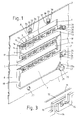
- Figure 1 shows an isometric view of a substantially planar plate of the invention
- Figure 2 shows an isometric view of a part of a structure of the invention which comprises a plurality of substantially planar plates
- Figure 3 shows an enlarged view of that part of the planar plate of Figure 1 indicated by the letter A.
- the planar plate 1 comprises a frame part 2 and three substantially horizontal bridging parts 3, 4 and 5 positioned between opposite vertical sides 6 and 7 of the frame part 2.
- the bridging parts 3, 4, 5 divide the planar plate into an upper cavity 8, a lower cavity 9 and two intermediate cavities 10 and 11.
- Each of the bridging parts 3, 4, 5 are of similar construction and one of the bridging parts only will be described in detail.
- the bridging part 3 comprises a groove 12 in a face of the bridging part along the length of the upper part of the bridging part, and six apertures leading from the lower part to the upper part of the bridging part. One only of these apertures, which is shown in greater detail in Figure 3, will be described.
- Each of the apertures is formed by a groove in the face of the bridging part and each groove comprises an opening 13 in the upper part of the bridging part, an opening 14 in the lower part of the bridging part, and a connecting part 15 between the openings 13, 14.
- the aperture also features a weir 16 the top of which is positioned at a level higher than that of the base of the connecting part 15 and over which liquid must pass in use if it is to flow through the aperture from the upper cavity 8 to the intermediate cavity 10.
- the height and width of the connecting part 15 may be varied to achieve in use a designed gas pressure drop between the intermediate cavity 10 and the upper cavity 8.
- the planar plate 1 also comprises a vertical groove 17 in a face of the plate in the vertical side 6 of the plate which groove leads from the upper cavity 8 to the intermediate cavity 10.
- the planar plate 1 comprises similar vertical grooves 18, 19 in the vertical sides 7 and 6 respectively of the plate which grooves lead respectively from the intermediate cavity 10 to the intermediate cavity 11 and from the intermediate cavity 11 to the lower cavity 9.
- the planar plate comprises an aperture 20 through a frame part of the plate 1 and three slots 21, 22 and 22a in a face of the plate and at right angles to the aperture 20 and leading from the aperture 20 to the lower cavity 9.
- the planar plate 1 also comprises an aperture 23 through a frame part of the plate 1.
- the planar plate 1 comprises an aperture 24 through a frame part of the plate 1 and three slots 25, 26, 27 in a face of the plate and at right angles to the aperture 24 and leading from the aperture 24 to the lower cavity 9.
- the planar plate comprises an aperture 28 through a frame part of the plate 1 and three slots 29, 30, 31 in a face of the plate and at right angles to the aperture 28 and leading from the aperture 28 to the upper cavity 8.
- the planar plate also comprises two apertures 32, 33 through a frame part of the plate and three slots 34, 35, 36 and three slots 37, 38, 39 in a face of the plate and at right angles to the apertures 32 and 33 and leading respectively from the apertures 32 and 33 to the upper cavity 8.
- the structure of the invention comprises a plurality of planar plates 1, 40, 41, 42, 43, 44 each of the plates 40, 41, 42, 43, 44 having a construction which is essentially the same as that of planar plate 1 and differing in one respect only from that of plate 1, as will be explained hereafter.
- the same reference numerals indicated on Figure 1 apply to the embodiment of Figure 2 but for the sake of clarity some only of these reference numerals are shown in Figure 2.
- the plates in the structure of Figure 2 are bonded together by means of an adhesive, and the structure comprises a stand pipe 45 which is positioned in suitably shaped slots in the plates 41, 42, 43, the stand pipe 45 leading from the lower cavity 9 to the aperture 23 in the plate 1 and similar apertures in the plates 40, 41, 42, 43, 44. It is in respect of this latter slot only in the plates 41, 42, 43 that these latter plates differ from the plate 1.
- the apertures 20, 23, 24, 28, 32, 33 in the plate 1 and similar apertures in the plates 40, 41, 42, 43, 44 together provide six separate compartments lengthwise of the structures.
- the structure of the invention is completed by end plates which for the sake of clarity have not been shown and which provide end walls for the structure and in particular for the cavities 8, 9, 10, 11.
- the positioning together of like planar plates 1, 40, 41, 42, 43, 44 converts the groove 12 in the upper part of the bridging part 3 of the planar plate 1 into a channel, and that the upper parts of the bridging parts in the planar plates are thus formed in the structure into a plurality of such channels.
- the positioning together of like planar plates converts the grooves in the faces of the bridging part having openings 13, 14 and connecting part 15 into channels leading from a lower part of the bridging part to an upper part of the bridging part, and the grooves 17, 18, 19 are similarly formed into channels or downcomers leading from an upper cavity of the structure to intermediate or lower cavities of the structure.
- the electrolytic cell which is not shown, is of the filter press type and comprises a plurality of anodes and plurality of cathodes each anode being separated from an adjacent cathode by a cation-exchange membrane thereby dividing the cell into a plurality of anode compartments and a plurality of cathode compartments.
- a cation-exchange membrane thereby dividing the cell into a plurality of anode compartments and a plurality of cathode compartments.
- aqueous alkali metal chloride solution is charged to the anode compartments and water or dilute aqeuous sodium hydroxide solution is charged to the cathode compartments, the sodium chloride is electrolysed and hot chlorine and hot depleted aqueous sodium chloride solution are discharged from the anode compartments, the sodium ions liberated in the electrolysis are transferred by the cation-exchange membranes from the anode compartments to the cathode compartments of the cell in which they react with water to form sodium hydroxide solution and hydrogen, and hot hydrogen and hot aqueous sodium hydroxide solution are discharged from the cathode compartments of the cell.
- Hot chlorine discharged from the anode compartments of the electrolytic cell is charged to the lengthwise compartment of which aperture 24 forms a part and thence through the associated slots 25, 26, 27 into lower cavity 9 of the structure.
- the chlorine gas then passes progressively upwards through the structure via apertures 46 in bridging part 5 and into intermediate cavity 11, via apertures 47 in bridging part 4 and into intermediate cavity 10, and finally via apertures 48 in bridging part 3 and into upper cavity 8.
- Chilled aqueous sodium chloride solution from a reservoir thereof is charged to the lengthwise compartment of which aperture 28 forms a part and thence through associated slots 29, 30, 31 into upper cavity 8 of the structure.
- the chilled solution fills the channels on the upper part of the bridging parts 3 formed by grooves 12, the solution passes through the channel formed by vertical groove 17 and into intermediate cavity 10 and fills the channels on the upper part of the bridging parts 4 formed by grooves 12, the solution then passes through the channel formed by vertical groove 18 and into intermediate cavity 11 and fills the channels on the upper part of the bridging part 5 formed by grooves 12, and finally the solution passes through the channel formed by vertical groove 19 and into lower cavity 9.
- the chlorine gas which passes to upper cavity 8 is cooled and is removed from cavity 8 via the lengthwise compartments of which apertures 32 and 33 form a part.
- the aqueous sodium chloride solution passes downwardly through channels 17, 18, 19 from upper cavity 8 to lower cavity 9 and the solution is progressively heated by contact with the chlorine gas.
- the tendency of aqueous sodium chloride solution to flow downwardly through apertures 48,47,46 on bridging parts 3,4,5 respectively is resisted by the presence of the weir 16 in each of the apertures.
- Hot aqueous sodium chloride solution which has been discharged from the electrolytic cell is also charged to lower cavity 9 through the lengthwise compartment of which aperture 20 forms a part and the associated slots.
- the hot aqueous sodium chloride solution discharged from the electrolytic cell is mixed with the aqueous sodium chloride solution which has been contacted with the chlorine and the mixed solutions are discharged from the structure through stand pipe 45 and the lengthwise compartment of which aperture 23 forms a part.
- the mixed solution is then charged to the anode compartments of the electrolytic cell for electrolysis, possibly after further purification and/or resaturation with sodium chloride.
Landscapes
- Chemical & Material Sciences (AREA)
- Chemical Kinetics & Catalysis (AREA)
- Engineering & Computer Science (AREA)
- Metallurgy (AREA)
- Organic Chemistry (AREA)
- Electrochemistry (AREA)
- Materials Engineering (AREA)
- General Engineering & Computer Science (AREA)
- Mechanical Engineering (AREA)
- Physical Or Chemical Processes And Apparatus (AREA)
- Gas Separation By Absorption (AREA)
- Absorbent Articles And Supports Therefor (AREA)
- Hybrid Cells (AREA)
- Feeding And Controlling Fuel (AREA)
- Treating Waste Gases (AREA)
- Inert Electrodes (AREA)
- Vaporization, Distillation, Condensation, Sublimation, And Cold Traps (AREA)
Claims (22)
- Im Wesentlichen ebene Platte (1), die sich für die Verwendung in einer Struktur eignet, welche eine oder mehrere im wesentlichen ebene Platten besitzt und in welcher ein direkter Kontakt zwischen einem Gas und einer Flüssigkeit bewerkstelligt werden kann, welche Platte (1) einen Rahmenteil (2) und zwischen einander gegenüberliegenden Seiten des Rahmenteils mindestens ein Brückenteil (3, 4, 5), welches die Platte in einen oberen und einen unteren Raum (8, 9) teilt, die durch das Rahmenteil und das Brückenteil begrenzt sind, sowie ein oder mehrere Durchgänge durch das Brückenteil, die vom unteren Raum zum oberen Raum führen, aufweist.
- Im wesentlichen ebene Platte 1 nach Anspruch 1, welche mehrere Brückenteile (3, 4, 5) aufweist, welche die Platte in einen oberen Raum (8), der durch das obere Brückenteil (3) und den Rahmenteil (2) begrenzt wird, einen unteren Raum (9), der durch das untere Brückenteil (5) und den Rahmenteil (2) begrenzt wird, und ein oder mehrere mittlere Räume (10, 11), die durch den Rahmenteil (2) und durch die Brückenteile (4, 5) begrenzt werden, unterteilen.
- Im wesentlichen ebene Platte (1) nach Anspruch 1 oder 2, bei welcher das Brückenteil (3, 4, 5) einen oberen Bereich aufweist, der einen offenen Kanal entlang der Länge des Brükkenteils besitzt.
- Im wesentlichen ebene Platte (1) nach Anspruch 3, bei welcher der Kanal durch eine Ausnehmung (12) entlang dem oberen Bereich des Brückenteils (3, 4, 5) gebildet wird.
- Im wesentlichen ebene Platte (1) nach Anspruch 4, bei welcher eine Ausnehmung (12) in einer Oberfläche des Brückenteils (3, 4, 5) entlang der Länge des Brückenteils ausgebildet ist, so daß ein Kanal im Brückenteil (3, 4, 5) gebildet wird, wenn das Brückenteil der im wesentlichen ebenen Platte die Nachbarschaft zu einer weiteren Platte in der erfindungsgemäßen Struktur angeordnet wird.
- Im wesentlichen ebene Platte (1) nach einem der Ansprüche 1 bis 5, bei welcher die Durchgänge durch die Brückenteile (3, 4, 5) der ebenen Platte durch Kanäle gebildet werden, die in den Brückenteilen ausgebildet sind.
- Im wesentlichen ebene Platte (1) nach einem der Ansprüche 1 bis 5, bei welcher die Brückenteile (3, 4, 5) in einer ihrer Oberflächen Schlitze aufweisen, so daß, wenn das Brückenteil einer ebenen Platte (1) an einem Brückenteil einer benachbarten Platte unter Bildung einer Struktur anliegt, durch die Brückenteile hindurchgehende Durchgänge gebildet werden.
- Im wesentlichen ebene Platte (1) nach einem der Ansprüche 1 bis 7, bei welcher die Abmessungen der Durchgänge in den Brückenteilen (3, 4, 5) der im wesentlichen ebenen Platte (1) derart sind, daß beim Gebrauch der Struktur Gas nach oben durch die Durchgänge hindurchgeht, aber wenig oder keine Flüssigkeit nach unten durch die Durchgänge hindurchgeht.
- Im wesentlichen ebene Platte (1) nach Anspruch 8, bei welcher die Durchgänge in den Brückenteilen (3, 4, 5) der ebenen Platte (1) so geformt sind, daß sie eine Barriere in Form eines Wehrs (16) bilden, über welches die Flüssigkeit fließen muß, wenn sie durch den Durchgang nach unten fließt.
- Im wesentlichen ebene Platte (1) nach Anspruch 8 oder 9, bei welcher die Durchgänge eine U-Form oder eine umgekehrte U-Form aufweisen.
- Im wesentlichen ebene Platte (1) nach einem der Ansprüche 1 bis 10, welche zwischen einem oberen Raum (8) und einem unteren Raum (9) mit einem Kanal oder einer Fallöffnung versehen ist, wodurch Flüssigkeit nach unten fließen kann.
- Im wesentlichen ebene Platte (1) nach Anspruch 11, bei welcher der Kanal oder die Fallöffnung in einem Rahmenteil der Platte (1) ausgebildet ist.
- Im wesentlichen ebene Platte (1) nach Anspruch 12, bei welcher der Kanal oder die Fallöffnung durch eine Ausnehmung (17, 18, 19) in der Oberfläche eines Rahmenteils (2) der Platte (1) ausgebildet ist, welche Ausnehmung in einen Kanal oder eine Fallöffnung im Rahmenteil umgebildet wird, wenn die ebene Platte an einer benachbarten ebenen Platte anliegt.
- Im wesentlichen ebene Platte (1) nach einem der Ansprüche 1 bis 13, welche eine rechteckige Form aufweist.
- Im wesentlichen ebene Platte (1) nach einem der Ansprüche 1 bis 14, bei welcher die Brückenteile (3, 4, 5) im wesentlichen horizontal verlaufen.
- Struktur, in welcher ein direkter Kontakt zwischen einem Gas und einer Flüssigkeit bewerkstelligt werden kann und welche eine oder mehrere im wesentlichen ebene Platten (1) nach einem der Ansprüche 1 bis 15 aufweist und welche ausgerüstet ist mit einer Einrichtung für die Zuführung von Flüssigkeit zu einem oberen Raum (8) der ebenen Platte (1) und einer Einrichtung für die Zuführung von Gas zu einem unteren Raum (9) der ebenen Platte (1) sowie mit einer Einrichtung zum Abführen von Gas aus einem oberen Raum (8) der ebenen Platte (1) und mit einer Einrichtung zum Abführen von Flüssigkeit aus einem unteren Raum (9) der ebenen Platte (1).
- Struktur nach Anspruch 16, bei welcher die Einrichtungen. durch welche Flüssigkeit zu und durch welche Gas aus einem oberen Raum (8) der ebenen Platte (1) geführt werden kann, und die Einrichtung, durch welche Gas zu und Flüssigkeit von einem unteren Raum (9) der ebenen Platte (1) geführt werden kann, durch Kanäle im Rahmenteil der ebenen Platte gebildet werden.
- Struktur nach Anspruch 17, bei welcher der Kanal durch ein Loch (28) durch die Dicke der ebenen Platte und durch einen Schlitz (29, 30, 31) oder der gleichen, der im wesentlichen im rechten Winkel zum Loch (28) verläuft und vom Loch zu einem oberen Raum (8) oder einem unteren Raum (9) der ebenen Platte (1) führt, gebildet wird.
- Struktur nach Anspruch 18, welche eine Anzahl von im wesentlichen ebenen Platten (1) aufweist, wobei die Löcher (20, 24, 28, 32, 33) durch die Dicke der Platte (1) gemeinsam in Längsrichtung der Struktur verlaufende Kanäle bilden.
- Struktur nach Anspruch 19, bei welcher die ebenen Platten (1) eine Anzahl solcher Löcher (20, 24, 28, 32, 33) im Rahmenteil (2) aufweisen, wodurch in der Struktur eine Anzahl von in Längsrichtung verlaufenden Kanälen gebildet wird, durch welche Gas der Struktur zu- und von der Struktur abgeführt werden kann und durch welche Flüssigkeit der Struktur zu- und von der Struktur abgeführt werden kann.
- Struktur nach einem der Ansprüche 16 bis 20, welche eine oder mehrere im wesentlichen ebene Platten aufweist, die eine Konstruktion besitzen, die sich von derjenigen der im wesentlichen ebenen Platten der Ansprüche 1 bis 15 unterscheidet.
- Struktur nach Anspruch 21, bei welcher die im wesentlichen ebenen Platten mit unterschiedlicher Konstruktion Endplatten der Struktur bilden.
Priority Applications (1)
| Application Number | Priority Date | Filing Date | Title |
|---|---|---|---|
| AT89311905T ATE90004T1 (de) | 1988-12-02 | 1989-11-16 | Struktur zur durchfuehrung eines gas-fluessigkeits- kontaktes und teile davon. |
Applications Claiming Priority (2)
| Application Number | Priority Date | Filing Date | Title |
|---|---|---|---|
| GB8828221 | 1988-12-02 | ||
| GB888828221A GB8828221D0 (en) | 1988-12-02 | 1988-12-02 | Structure for effecting gas-liquid contact & part thereof |
Publications (2)
| Publication Number | Publication Date |
|---|---|
| EP0373772A1 EP0373772A1 (de) | 1990-06-20 |
| EP0373772B1 true EP0373772B1 (de) | 1993-06-02 |
Family
ID=10647883
Family Applications (1)
| Application Number | Title | Priority Date | Filing Date |
|---|---|---|---|
| EP89311905A Expired - Lifetime EP0373772B1 (de) | 1988-12-02 | 1989-11-16 | Struktur zur Durchführung eines Gas-Flüssigkeits-Kontaktes und Teile davon |
Country Status (15)
| Country | Link |
|---|---|
| US (1) | US5024788A (de) |
| EP (1) | EP0373772B1 (de) |
| JP (1) | JP2809453B2 (de) |
| KR (1) | KR0133663B1 (de) |
| CN (1) | CN1039972C (de) |
| AT (1) | ATE90004T1 (de) |
| AU (1) | AU616823B2 (de) |
| CA (1) | CA2003483C (de) |
| DE (1) | DE68906868T2 (de) |
| ES (1) | ES2040472T3 (de) |
| FI (1) | FI94375C (de) |
| GB (2) | GB8828221D0 (de) |
| HK (1) | HK1006815A1 (de) |
| NO (1) | NO176237C (de) |
| ZA (1) | ZA898841B (de) |
Families Citing this family (2)
| Publication number | Priority date | Publication date | Assignee | Title |
|---|---|---|---|---|
| KR100643985B1 (ko) * | 2000-01-19 | 2006-11-13 | 엘지엔시스(주) | 고객카드를 이용한 금융업무 처리시스템 |
| DE102007062976A1 (de) * | 2007-12-21 | 2009-06-25 | INSTITUT FüR MIKROTECHNIK MAINZ GMBH | Mikrorektifikationskolonne für die thermische Trennung von Flüssigkeiten |
Family Cites Families (15)
| Publication number | Priority date | Publication date | Assignee | Title |
|---|---|---|---|---|
| US1108853A (en) * | 1910-10-21 | 1914-08-25 | Benjamin F Brooke Sewell | Apparatus for scrubbing or similarly treating liquids and gases. |
| DE903447C (de) * | 1936-09-19 | 1954-02-08 | Walter Kittel Dipl Ing | Austauschboden fuer Kolonnen |
| FR886023A (fr) * | 1941-09-29 | 1943-10-01 | Ig Farbenindustrie Ag | Plateau de colonne de rectification |
| US3039750A (en) * | 1952-03-07 | 1962-06-19 | Kittel Walter | Contact plate structure for use in a rectifying or contacting column |
| US2880980A (en) * | 1955-07-05 | 1959-04-07 | Socony Mobil Oil Co Inc | Low pressure drop fractionating tray |
| US2877099A (en) * | 1956-08-15 | 1959-03-10 | Socony Mobil Oil Co | Multistage concurrent-countercurrent liquid gas contact and apparatus therefor |
| GB1143772A (de) * | 1965-03-15 | |||
| US3475134A (en) * | 1965-05-05 | 1969-10-28 | Hydrocarbon Research Inc | Liquid phase reactor |
| DE1904144C3 (de) * | 1969-01-28 | 1974-01-31 | Linde Ag, 6200 Wiesbaden | Vorrichtung zum Inkontaktbringen von Gasen mit Flüssigkeiten |
| US3914347A (en) * | 1973-07-23 | 1975-10-21 | Aerojet General Co | Platelet-injector venturi carburetor for internal combustion engines |
| US4118285A (en) * | 1975-04-29 | 1978-10-03 | Villanova University | Separation of liquid mixtures |
| US3983191A (en) * | 1975-11-10 | 1976-09-28 | The Trane Company | Brazed plate-type heat exchanger for nonadiabatic rectification |
| DE2804680A1 (de) * | 1978-02-03 | 1979-08-09 | Linde Ag | Rektifikationskolonne mit horizontalen austauschboeden |
| US4547326A (en) * | 1981-02-27 | 1985-10-15 | Union Carbide Corporation | Gas liquid contacting tray |
| GB8531685D0 (en) * | 1985-12-23 | 1986-02-05 | Boc Group Plc | Liquid-vapour contact apparatus |
-
1988
- 1988-12-02 GB GB888828221A patent/GB8828221D0/en active Pending
-
1989
- 1989-11-16 AT AT89311905T patent/ATE90004T1/de not_active IP Right Cessation
- 1989-11-16 EP EP89311905A patent/EP0373772B1/de not_active Expired - Lifetime
- 1989-11-16 ES ES198989311905T patent/ES2040472T3/es not_active Expired - Lifetime
- 1989-11-16 DE DE8989311905T patent/DE68906868T2/de not_active Expired - Fee Related
- 1989-11-16 GB GB898925901A patent/GB8925901D0/en active Pending
- 1989-11-20 ZA ZA898841A patent/ZA898841B/xx unknown
- 1989-11-21 CA CA002003483A patent/CA2003483C/en not_active Expired - Fee Related
- 1989-11-23 NO NO894668A patent/NO176237C/no not_active IP Right Cessation
- 1989-11-30 JP JP1309449A patent/JP2809453B2/ja not_active Expired - Lifetime
- 1989-12-01 FI FI895758A patent/FI94375C/fi not_active IP Right Cessation
- 1989-12-01 US US07/444,790 patent/US5024788A/en not_active Expired - Fee Related
- 1989-12-01 AU AU45803/89A patent/AU616823B2/en not_active Ceased
- 1989-12-02 KR KR1019890017825A patent/KR0133663B1/ko not_active Expired - Fee Related
- 1989-12-02 CN CN89109078A patent/CN1039972C/zh not_active Expired - Fee Related
-
1998
- 1998-06-01 HK HK98104732A patent/HK1006815A1/en not_active IP Right Cessation
Also Published As
| Publication number | Publication date |
|---|---|
| ATE90004T1 (de) | 1993-06-15 |
| JPH02211239A (ja) | 1990-08-22 |
| FI94375C (fi) | 1995-08-25 |
| NO894668L (no) | 1990-06-05 |
| DE68906868T2 (de) | 1993-09-09 |
| AU616823B2 (en) | 1991-11-07 |
| DE68906868D1 (de) | 1993-07-08 |
| CN1039972C (zh) | 1998-09-30 |
| FI94375B (fi) | 1995-05-15 |
| CA2003483C (en) | 2000-02-01 |
| JP2809453B2 (ja) | 1998-10-08 |
| NO176237B (no) | 1994-11-21 |
| NO894668D0 (no) | 1989-11-23 |
| EP0373772A1 (de) | 1990-06-20 |
| CA2003483A1 (en) | 1990-06-02 |
| FI895758A0 (fi) | 1989-12-01 |
| US5024788A (en) | 1991-06-18 |
| KR900009119A (ko) | 1990-07-02 |
| CN1043094A (zh) | 1990-06-20 |
| GB8925901D0 (en) | 1990-01-04 |
| GB8828221D0 (en) | 1989-01-05 |
| AU4580389A (en) | 1990-06-07 |
| ES2040472T3 (es) | 1993-10-16 |
| KR0133663B1 (ko) | 1998-04-18 |
| HK1006815A1 (en) | 1999-03-19 |
| ZA898841B (en) | 1990-08-29 |
| NO176237C (no) | 1995-03-01 |
Similar Documents
| Publication | Publication Date | Title |
|---|---|---|
| US4740287A (en) | Multilayer electrode electrolytic cell | |
| FI67728B (fi) | Bipolaer film- eller membranelektrolyseringsanordning | |
| US4069129A (en) | Electrolytic cell | |
| NO167470B (no) | Fremgangsmaate for elektrolyse av flytende elektrolytter. | |
| US4761216A (en) | Multilayer electrode | |
| US5024788A (en) | Structure for effecting gas-liquid and part thereof | |
| EP0521386B1 (de) | Elektrolyseur und Herstellung davon | |
| US4832804A (en) | Electrolytic cell | |
| US4770756A (en) | Electrolytic cell apparatus | |
| HK1006815B (en) | Structure for effecting gas-liquid contact and part thereof | |
| US5021199A (en) | Sieve plate for effecting gas-liquid contact and structure containing sieve plate | |
| US4093531A (en) | Apparatus for concentration and purification of a cell liquor in an electrolytic cell | |
| US3645882A (en) | Carbonation process for so2 removal | |
| US4596639A (en) | Electrolysis process and electrolytic cell | |
| RU2126462C1 (ru) | Электрод, электролизер, способ изготовления электрода и способ электролиза | |
| US4568433A (en) | Electrolytic process of an aqueous alkali metal halide solution | |
| GB2240988A (en) | Membrane electrolytic cell incorporating separator | |
| US4822461A (en) | Electrolytic cell | |
| US5034029A (en) | Apparatus for effecting gas-liquid contact | |
| US4395321A (en) | Separator electrolytic cell | |
| GB2239660A (en) | Porous, sintered, multilayer electrode for electrolytic membrane cell | |
| JPS5881983A (ja) | 複極式電解槽 |
Legal Events
| Date | Code | Title | Description |
|---|---|---|---|
| PUAI | Public reference made under article 153(3) epc to a published international application that has entered the european phase |
Free format text: ORIGINAL CODE: 0009012 |
|
| AK | Designated contracting states |
Kind code of ref document: A1 Designated state(s): AT BE CH DE ES FR GB IT LI LU NL SE |
|
| 17P | Request for examination filed |
Effective date: 19901117 |
|
| 17Q | First examination report despatched |
Effective date: 19920723 |
|
| GRAA | (expected) grant |
Free format text: ORIGINAL CODE: 0009210 |
|
| AK | Designated contracting states |
Kind code of ref document: B1 Designated state(s): AT BE CH DE ES FR GB IT LI LU NL SE |
|
| REF | Corresponds to: |
Ref document number: 90004 Country of ref document: AT Date of ref document: 19930615 Kind code of ref document: T |
|
| ITF | It: translation for a ep patent filed | ||
| REF | Corresponds to: |
Ref document number: 68906868 Country of ref document: DE Date of ref document: 19930708 |
|
| ET | Fr: translation filed | ||
| REG | Reference to a national code |
Ref country code: ES Ref legal event code: FG2A Ref document number: 2040472 Country of ref document: ES Kind code of ref document: T3 |
|
| EPTA | Lu: last paid annual fee | ||
| PLBE | No opposition filed within time limit |
Free format text: ORIGINAL CODE: 0009261 |
|
| STAA | Information on the status of an ep patent application or granted ep patent |
Free format text: STATUS: NO OPPOSITION FILED WITHIN TIME LIMIT |
|
| 26N | No opposition filed | ||
| EAL | Se: european patent in force in sweden |
Ref document number: 89311905.7 |
|
| PG25 | Lapsed in a contracting state [announced via postgrant information from national office to epo] |
Ref country code: LU Free format text: LAPSE BECAUSE OF NON-PAYMENT OF DUE FEES Effective date: 19981116 |
|
| PGFP | Annual fee paid to national office [announced via postgrant information from national office to epo] |
Ref country code: LU Payment date: 19991019 Year of fee payment: 10 |
|
| REG | Reference to a national code |
Ref country code: CH Ref legal event code: NV Representative=s name: BOVARD AG PATENTANWAELTE |
|
| PGFP | Annual fee paid to national office [announced via postgrant information from national office to epo] |
Ref country code: AT Payment date: 20001006 Year of fee payment: 12 |
|
| PGFP | Annual fee paid to national office [announced via postgrant information from national office to epo] |
Ref country code: FR Payment date: 20001009 Year of fee payment: 12 |
|
| PGFP | Annual fee paid to national office [announced via postgrant information from national office to epo] |
Ref country code: SE Payment date: 20001016 Year of fee payment: 12 Ref country code: CH Payment date: 20001016 Year of fee payment: 12 |
|
| PGFP | Annual fee paid to national office [announced via postgrant information from national office to epo] |
Ref country code: GB Payment date: 20001017 Year of fee payment: 12 |
|
| PGFP | Annual fee paid to national office [announced via postgrant information from national office to epo] |
Ref country code: NL Payment date: 20001020 Year of fee payment: 12 Ref country code: DE Payment date: 20001020 Year of fee payment: 12 |
|
| PGFP | Annual fee paid to national office [announced via postgrant information from national office to epo] |
Ref country code: ES Payment date: 20001107 Year of fee payment: 12 Ref country code: BE Payment date: 20001107 Year of fee payment: 12 |
|
| PG25 | Lapsed in a contracting state [announced via postgrant information from national office to epo] |
Ref country code: GB Free format text: LAPSE BECAUSE OF NON-PAYMENT OF DUE FEES Effective date: 20011116 Ref country code: AT Free format text: LAPSE BECAUSE OF NON-PAYMENT OF DUE FEES Effective date: 20011116 |
|
| PG25 | Lapsed in a contracting state [announced via postgrant information from national office to epo] |
Ref country code: SE Free format text: LAPSE BECAUSE OF NON-PAYMENT OF DUE FEES Effective date: 20011117 Ref country code: ES Free format text: LAPSE BECAUSE OF NON-PAYMENT OF DUE FEES Effective date: 20011117 |
|
| PG25 | Lapsed in a contracting state [announced via postgrant information from national office to epo] |
Ref country code: LI Free format text: LAPSE BECAUSE OF NON-PAYMENT OF DUE FEES Effective date: 20011130 Ref country code: CH Free format text: LAPSE BECAUSE OF NON-PAYMENT OF DUE FEES Effective date: 20011130 Ref country code: BE Free format text: LAPSE BECAUSE OF NON-PAYMENT OF DUE FEES Effective date: 20011130 |
|
| REG | Reference to a national code |
Ref country code: GB Ref legal event code: IF02 |
|
| BERE | Be: lapsed |
Owner name: IMPERIAL CHEMICAL INDUSTRIES P.L.C. Effective date: 20011130 |
|
| PG25 | Lapsed in a contracting state [announced via postgrant information from national office to epo] |
Ref country code: NL Free format text: LAPSE BECAUSE OF NON-PAYMENT OF DUE FEES Effective date: 20020601 |
|
| EUG | Se: european patent has lapsed |
Ref document number: 89311905.7 |
|
| PG25 | Lapsed in a contracting state [announced via postgrant information from national office to epo] |
Ref country code: DE Free format text: LAPSE BECAUSE OF NON-PAYMENT OF DUE FEES Effective date: 20020702 |
|
| REG | Reference to a national code |
Ref country code: CH Ref legal event code: PL |
|
| PG25 | Lapsed in a contracting state [announced via postgrant information from national office to epo] |
Ref country code: FR Free format text: LAPSE BECAUSE OF NON-PAYMENT OF DUE FEES Effective date: 20020730 |
|
| NLV4 | Nl: lapsed or anulled due to non-payment of the annual fee |
Effective date: 20020601 |
|
| REG | Reference to a national code |
Ref country code: FR Ref legal event code: ST |
|
| REG | Reference to a national code |
Ref country code: FR Ref legal event code: ST |
|
| REG | Reference to a national code |
Ref country code: ES Ref legal event code: FD2A Effective date: 20021213 |
|
| PG25 | Lapsed in a contracting state [announced via postgrant information from national office to epo] |
Ref country code: IT Free format text: LAPSE BECAUSE OF NON-PAYMENT OF DUE FEES;WARNING: LAPSES OF ITALIAN PATENTS WITH EFFECTIVE DATE BEFORE 2007 MAY HAVE OCCURRED AT ANY TIME BEFORE 2007. THE CORRECT EFFECTIVE DATE MAY BE DIFFERENT FROM THE ONE RECORDED. Effective date: 20051116 |