EP0373802A2 - Frequenzmessung - Google Patents
Frequenzmessung Download PDFInfo
- Publication number
- EP0373802A2 EP0373802A2 EP89312577A EP89312577A EP0373802A2 EP 0373802 A2 EP0373802 A2 EP 0373802A2 EP 89312577 A EP89312577 A EP 89312577A EP 89312577 A EP89312577 A EP 89312577A EP 0373802 A2 EP0373802 A2 EP 0373802A2
- Authority
- EP
- European Patent Office
- Prior art keywords
- phase
- signal
- values
- frequency
- time intervals
- Prior art date
- Legal status (The legal status is an assumption and is not a legal conclusion. Google has not performed a legal analysis and makes no representation as to the accuracy of the status listed.)
- Granted
Links
- 238000005259 measurement Methods 0.000 title claims description 25
- 230000001186 cumulative effect Effects 0.000 claims abstract description 23
- 238000005070 sampling Methods 0.000 claims abstract description 18
- 238000000034 method Methods 0.000 claims description 28
- 230000008859 change Effects 0.000 description 4
- 239000013598 vector Substances 0.000 description 4
- 230000008569 process Effects 0.000 description 2
- 230000008707 rearrangement Effects 0.000 description 2
- 230000009466 transformation Effects 0.000 description 2
- 230000001934 delay Effects 0.000 description 1
- 230000003111 delayed effect Effects 0.000 description 1
- 238000010586 diagram Methods 0.000 description 1
- 230000000694 effects Effects 0.000 description 1
- 238000003780 insertion Methods 0.000 description 1
- 230000037431 insertion Effects 0.000 description 1
- 238000000691 measurement method Methods 0.000 description 1
- 238000013139 quantization Methods 0.000 description 1
- 230000009467 reduction Effects 0.000 description 1
- 238000009827 uniform distribution Methods 0.000 description 1
Images


Classifications
-
- G—PHYSICS
- G01—MEASURING; TESTING
- G01R—MEASURING ELECTRIC VARIABLES; MEASURING MAGNETIC VARIABLES
- G01R23/00—Arrangements for measuring frequencies; Arrangements for analysing frequency spectra
- G01R23/02—Arrangements for measuring frequency, e.g. pulse repetition rate; Arrangements for measuring period of current or voltage
- G01R23/12—Arrangements for measuring frequency, e.g. pulse repetition rate; Arrangements for measuring period of current or voltage by converting frequency into phase shift
Definitions
- This invention relates to frequency measurement. Frequency measurement of an incoming signal is required in a number of circumstances, for example for measuring the centre frequency of radio and microwave signals.
- Known methods of frequency measurement include the use of pulse counting, as described for example in UK Patent Application GB 2196497A.
- An alternative method of frequency measurement involves the use of transformation techniques for transferring between the time domain to the frequency domain, as described for example in US Patent No. 4,743,905.
- a method for measuring the frequency of a signal comprises: obtaining values of the cumulative phase of the signal at a succession of time intervals, and determining the gradient of the straight line which would best pass through a plot of the values against time so as to obtain an estimate of the frequency of the signal.
- the invention thus resides in the appreciation by the inventors that it is possible to obtain estimates of the frequency of a signal from measurements of the cumulative phase of the signal without it being necessary to measure other parameters such as the amplitude of the signal.
- By use of such a method it is possible to obtain a frequency measurement to a particular accuracy in a much shorter time than is generally achieved by known frequency measurement techniques.
- the values of the cumulative phase are obtained by means of a quadrature sampling method.
- the estimated frequency thus corresponds to the difference in frequency between the frequency of a local oscillator, and the carrier frequency of an input signal.
- the gradient of the straight line may be obtained by means of a least squares fit technique.
- an apparatus for measuring the frequency of a signal comprises: means for obtaining values of the cumulative phase of the signal at a succession of time intervals; and means for determining the gradient of the straight line which would best pass through a plot of the values against time so as to obtain an estimate of the frequency of the signal.
- the first apparatus to be described is a high precision system using a quadrature sampling system for obtaining digital values of the instantaneous phase ⁇ (n) measured at any particular time n of an input signal at equal time intervals.
- the apparatus also includes further stages for converting the phase ⁇ (n) into cumulative phase y(n) and hardware for implementing a least squares fit procedure to determine the gradient of the line which best passes through a plot of the cumulative phase y(n) against sampling intervals.
- the incoming signal whose frequency it is required to determine, is split equally between two channels by signal splitter 1.
- the split signal in the first channel, the 'inphase' or I channel is multiplied at multiplier 3 by a sinusoidal signal from a local oscillator 5.
- the split signal in the second channel, the 'quadrature' or Q channel is multiplied at multiplier 7 by the same local oscillator signal after it has been phase shifted by 90 degrees at the phase shifter 9.
- the resultant signals in the two channels are then filtered by respective low-pass filters 11, 13 to remove the upper sideband, and digitised by respective analogue/digital converters 15, 17, the two channels being matched such that the digitisation in the two channels occurs simultaneously.
- the resultant digital numbers in each channel describe the I and Q components of a signal of carrier frequency equal to the difference between the signal generated by the local oscillator 5 and the frequency of the input signal, where the input signal is sinusoidal, or the carrier frequency of the input signal where the input signal is a modulated sinusoidal.
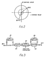
- the phase ⁇ (n) of the signal may be represented graphically as illustrated in Figure 2, as a vector rotating in a circle. The amplitude of the signal is given by the magnitude of this vector, whilst the phase ⁇ (n) is equal to the arc tangent of the ratio of the signals in the Q and I channels. In the particular apparatus being described, however, the value of ⁇ (n) is derived from the I and Q digital numbers using a look-up table 19.
- each value of ⁇ (n) will lie between minus 180 degrees and plus 180 degrees.
- the difference between successive phase measurements ⁇ (n), ⁇ (n+1) must be added to the last cumulative phase value to create the next value this process being known as "phase unwrapping".
- phase unwrapping It will be seen from Figure 2 that obtaining the correct phase difference ⁇ (n+1) - ⁇ (n) will depend on correctly interpreting the direction, i.e. clockwise or anticlockwise, in which the signal phase has changed between the two measurements. If relatively rapid phase measurements are made to high precision it may be assumed that the phase change has occurred in the direction of least distance.
- Figure 3 illustrates schematically the hardware used to create the cumulative phase y(n).
- a portion of the digital signal ⁇ (n) is delayed by one time unit in the unit delay 21.
- a phase difference device 23 creating two values of the phase difference from the present ⁇ (n) and previous ⁇ (n-1) values of the measured phase, one value of the phase difference describing a clockwise rotation of the vector in Figure 2, the other an anti-clockwise rotation.
- the device 23 may be constituted by a look-up table, each entry of which contains two values, or alternatively by two digital subtraction circuits.
- a selector circuit 25 chooses one of the two values of phase difference, for a high precision system this decision being made by a magnitude comparator which chooses the smallest value.
- An accumulator comprising an adder 27, and a unit delay then produces a set of values y(i) where i defines equal time intervals 0, 1, 2, 3, ... (n-1),n, ... (N-1), N being the number of samples.
- This line will have a gradient which is equivalent to the difference in frequencies between the input signal and that of the local oscillator 5.
- a least squares fit technique may be used to give an estimate ⁇ of the value of w from the set of values of y(i) as follows.
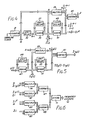
- the same sampling clock used to clock the analogue/digital converters 15, 17 shown in Figure 1 is used to address a counter 31 to produce the required value of N.
- This value forms an input into a unit delay circuit 33, and an accumulator 35, 37 arranged to give a further output
- a multiplier 39, further accumulator 41, 43 and subtractor 45 are arranged as indicated in the figure to give a third output
- this circuit operates in an equivalent manner to that of Figure 4 to produce an output ⁇ y(i) using an accumulator 47, 49 from an input of y(i), and an output of ⁇ i y(i) from the values of N and y(i) using a further accumulator 51, 53, a multiplier 55, and a subtractor 57.
- N, ⁇ iy(i), ⁇ y(i), ⁇ i2 produced by the circuits shown in Figures 4 and 5, together with the arrangement of multipliers 59, 61 and 65, subtractors 67, 69 and divider 71 shown in Figure 6, and estimate ⁇ of the required frequency may be derived from equation 7.
- the apparatus may be used for very high speed operation. Only the simple operations of addition and delay take place at the sampling clock rate, the multiplications and divisions only being necessary each time the frequency estimate is updated, which can be at a sub-multiple of the clock rate.
- the estimate w thus derived is the best estimate that can be obtained from the sampled data.
- the errors in the y(i) points will then be due to the phase quantisation. Assuming that the phase error has a uniform distribution over one quantisation interval, if the analogue/digital converters 15, 17 and look-up table 19 of Figure 1 give p phase quantisation levels the r.m.s. quantisation error is 211/p ⁇ 12 .
- the apparatus described herebefore has been designed to give the capability of high accuracy measurements.
- This system would then only be capable of distinguishing the four phase states in each of the I-Q quadrants in the graphical representation of Figure 2, with all amplitude information being lost.
- the dynamic range of the system would then in principle be infinite and no phase look-up table would be required.
- Such a system suffers the disadvantage however that a large amount of noise will be superimposed on the true phase signal ⁇ (n). Assuming, however, that the sense in which the phase signal rotates does not change over a period of several samples, a phase change histogram may be created over this period, the phase change histogram being interpreted in such a way that its variance is minimised.
- the second apparatus to be described incorporates equivalent quadrature sampling and phase unwrapping systems to those used in the first apparatus.
- the hardware used to obtain the required frequency estimation from the cumulative phase values y(i) is simplified however at the expense of accuracy in the frequency estimates. This may be achieved by assuming that the estimated phase intercept b is zero.
- rearrangement of equation 5 yields
- the combinations of counter, unit delays, adders, multipliers, and subtractors are the same as those shown in Figures 5 and 6 in respect of the first apparatus, and are thus equivalently labelled. Only values of N and ⁇ i2 are obtained from the circuit shown in Figure 7 however, with only a value of ⁇ iy(i) being obtained from the circuit shown in Figure 8.
- an estimate of the required frequency is obtained by using a divider 5 to obtain a value for the ratio
- the third apparatus to be described achieves a further reduction in the hardware used to obtain the required frequency estimation from the cumulative phase values y(i).
- the apparatus includes a counter 61 responsive to the sampling clock to produce a value of N.
- the values of y(i) are input into an accumulator 63, 65 to produce the term a divider then producing the ratio
- the error ⁇ in the value of ⁇ using the third apparatus is given by
- the frequency of a 1 microsecond pulse in the frequency range 2.5 GHz to 3.5 GHz may be estimated with an r.m.s. error of 14 kHz. If the apparatus illustrated in Figure 10 is used, this error is increased to 114 kHz.
- each of the apparatus described herebefore employ a quadrature sampling system to measure the phase of an incoming signal
- the invention is applicable to apparatus in which the required phase measurements are achieved by alternative means.
- One such alternative means is a Hilbert transformation technique in which all positive frequencies are given a 90 degree phase advance and all negative frequencies are given a 90 degree phase lag. The input signal and its transformed version are then used as the equivalent I and Q channels and the phase deduced as described herebefore. Whilst such a technique leads to a sign ambiguity in the true instantaneous phase as positive and negative frequencies are indistinguishable, this may be resolved by assuming that all phase vectors rotate in the same direction, i.e. all frequencies are positive.
- phase signal processing apparatus it is particularly apt to implement the phase signal processing apparatus digitally, it would also be possible to implement an apparatus according to the invention in analogue form.
Landscapes
- Physics & Mathematics (AREA)
- General Physics & Mathematics (AREA)
- Measuring Frequencies, Analyzing Spectra (AREA)
- Measuring Phase Differences (AREA)
- Stabilization Of Oscillater, Synchronisation, Frequency Synthesizers (AREA)
- General Induction Heating (AREA)
- Control Of High-Frequency Heating Circuits (AREA)
Priority Applications (1)
| Application Number | Priority Date | Filing Date | Title |
|---|---|---|---|
| AT8989312577T ATE105637T1 (de) | 1988-12-10 | 1989-12-01 | Frequenzmessung. |
Applications Claiming Priority (2)
| Application Number | Priority Date | Filing Date | Title |
|---|---|---|---|
| GB888828912A GB8828912D0 (en) | 1988-12-10 | 1988-12-10 | Frequency measurement |
| GB8828912 | 1988-12-10 |
Publications (3)
| Publication Number | Publication Date |
|---|---|
| EP0373802A2 true EP0373802A2 (de) | 1990-06-20 |
| EP0373802A3 EP0373802A3 (de) | 1991-05-29 |
| EP0373802B1 EP0373802B1 (de) | 1994-05-11 |
Family
ID=10648322
Family Applications (1)
| Application Number | Title | Priority Date | Filing Date |
|---|---|---|---|
| EP89312577A Expired - Lifetime EP0373802B1 (de) | 1988-12-10 | 1989-12-01 | Frequenzmessung |
Country Status (5)
| Country | Link |
|---|---|
| US (1) | US5019823A (de) |
| EP (1) | EP0373802B1 (de) |
| AT (1) | ATE105637T1 (de) |
| DE (1) | DE68915255T2 (de) |
| GB (1) | GB8828912D0 (de) |
Cited By (9)
| Publication number | Priority date | Publication date | Assignee | Title |
|---|---|---|---|---|
| RU2183839C1 (ru) * | 2000-10-30 | 2002-06-20 | Государственное конструкторское бюро аппаратно-программных систем "Связь" Всероссийского НИИ "Градиент" | Способ измерения частоты синусоидальных сигналов и устройство для его реализации |
| GB2376859A (en) * | 2001-02-15 | 2002-12-24 | Central Research Lab Ltd | A method of estimating the carrier frequency of a phase-modulated signal |
| WO2006030188A1 (en) * | 2004-09-13 | 2006-03-23 | Filtronic Plc | Method and apparatus for measuring the frequency of a received signal |
| RU2339958C1 (ru) * | 2007-04-25 | 2008-11-27 | Федеральное государственное унитарное предприятие "Государственное бюро аппаратно-программных систем "Связь" (ФГУП "ГКБ "Связь") | Способ измерения частоты синусоидальных сигналов и устройство для его реализации |
| RU2363004C2 (ru) * | 2006-09-29 | 2009-07-27 | Федеральное государственное унитарное предприятие "Государственное конструкторское бюро аппаратно-программных систем "Связь" (ФГУП "ГКБ "Связь") | Способ измерения частоты синусоидальных сигналов и устройство для его реализации |
| CN104062494A (zh) * | 2014-05-30 | 2014-09-24 | 深圳市中电软件有限公司 | 一种抑制频谱泄漏的采样间隔补偿方法及系统 |
| CN104502702A (zh) * | 2014-12-10 | 2015-04-08 | 广东电网有限责任公司电力科学研究院 | 检测电力信号的频率的方法和系统 |
| WO2025116968A1 (en) * | 2023-12-01 | 2025-06-05 | Microchip Technology Incorporated | Apparatus and method for clock frequency estimation with least squares method |
| US12411159B2 (en) | 2023-12-01 | 2025-09-09 | Microchip Technology Incorporated | Apparatus and method for clock frequency estimation with least squares method |
Families Citing this family (11)
| Publication number | Priority date | Publication date | Assignee | Title |
|---|---|---|---|---|
| IT1244206B (it) * | 1990-12-19 | 1994-07-08 | Telettra Spa | Sistema e circuito per la stima della frequenza di portante di un segnale |
| US5644320A (en) * | 1994-06-30 | 1997-07-01 | Compaq Computer Corporation | Antenna system for a notebook computer |
| US5790566A (en) * | 1994-08-31 | 1998-08-04 | Hughes Electronics | Method and device for depuncturing data |
| US5687163A (en) * | 1995-06-07 | 1997-11-11 | Cirrus Logic, Inc. | Method and apparatus for signal classification using I/Q quadrant histogram |
| US5714876A (en) * | 1996-04-24 | 1998-02-03 | Tektronix, Inc. | In-service serial digital source signal-level and cable-length measurement |
| US20010055348A1 (en) * | 2000-03-31 | 2001-12-27 | Anderson Christopher L. | Sequential quadrant demodulation of digitally modulated radio signals |
| DE10052304C2 (de) * | 2000-10-20 | 2002-09-12 | Eads Deutschland Gmbh | Vorrichtung und Verfahren zur Frequenzmessung mit Integration der Signalphase |
| US6743278B1 (en) * | 2002-12-10 | 2004-06-01 | Advanced Technology Materials, Inc. | Gas storage and dispensing system with monolithic carbon adsorbent |
| US8868364B2 (en) * | 2011-04-29 | 2014-10-21 | Analog Devices, Inc. | Apparatus and method for real time harmonic spectral analyzer |
| RU2517799C1 (ru) * | 2012-12-21 | 2014-05-27 | Федеральное государственное автономное образовательное учреждение высшего профессионального образования "Балтийский Федеральный Университет имени Иммануила Канта" (БФУ им. И. Канта) | Способ определения параметров широкополосного сигнала |
| JP6954765B2 (ja) * | 2017-05-24 | 2021-10-27 | Necネットワーク・センサ株式会社 | 周波数計測装置、周波数計測方法、およびプログラム |
Family Cites Families (10)
| Publication number | Priority date | Publication date | Assignee | Title |
|---|---|---|---|---|
| DE2738832C2 (de) * | 1977-08-29 | 1979-06-28 | Siemens Ag, 1000 Berlin Und 8000 Muenchen | Schaltungsanordnung zur Verschiebung des Ciutterspektrums bei einem Radarempfänger |
| DE2833335A1 (de) * | 1978-07-29 | 1980-03-06 | Licentia Gmbh | Digitaler frequenzdiskriminator |
| US4291269A (en) * | 1979-06-28 | 1981-09-22 | Rca Corporation | System and method for frequency discrimination |
| JPS57133362A (en) * | 1981-02-10 | 1982-08-18 | Mitsubishi Electric Corp | Frequency detector |
| US4504786A (en) * | 1982-06-14 | 1985-03-12 | Slaughter Grimes G | Signal detector |
| FR2535462A1 (fr) * | 1982-10-29 | 1984-05-04 | Labo Electronique Physique | Circuit numerique de mesure de la frequence instantanee d'un signal module ou non en frequence, ainsi que recepteur de television ou de radio equipe d'un tel circuit |
| US4542657A (en) * | 1983-08-26 | 1985-09-24 | General Electric Company | Time domain technique to determine mean frequency |
| US4633516A (en) * | 1985-05-30 | 1986-12-30 | United States Of America As Represented By The Secretary Of The Air Force | Instantaneous frequency measurement receiver with digital processing |
| US4743905A (en) * | 1985-08-16 | 1988-05-10 | Westinghouse Electric Corp. | Electronic counter measure system utilizing a digital RF memory |
| FR2615626B1 (fr) * | 1987-05-21 | 1989-07-28 | Alcatel Espace | Procede d'evaluation numerique de la frequence et de la phase de signaux et dispositifs de mise en oeuvre d'un tel procede |
-
1988
- 1988-12-10 GB GB888828912A patent/GB8828912D0/en active Pending
-
1989
- 1989-12-01 DE DE68915255T patent/DE68915255T2/de not_active Expired - Fee Related
- 1989-12-01 EP EP89312577A patent/EP0373802B1/de not_active Expired - Lifetime
- 1989-12-01 AT AT8989312577T patent/ATE105637T1/de not_active IP Right Cessation
- 1989-12-05 US US07/446,543 patent/US5019823A/en not_active Expired - Fee Related
Cited By (16)
| Publication number | Priority date | Publication date | Assignee | Title |
|---|---|---|---|---|
| RU2183839C1 (ru) * | 2000-10-30 | 2002-06-20 | Государственное конструкторское бюро аппаратно-программных систем "Связь" Всероссийского НИИ "Градиент" | Способ измерения частоты синусоидальных сигналов и устройство для его реализации |
| GB2376859A (en) * | 2001-02-15 | 2002-12-24 | Central Research Lab Ltd | A method of estimating the carrier frequency of a phase-modulated signal |
| GB2376859B (en) * | 2001-02-15 | 2003-09-24 | Central Research Lab Ltd | A method of estimating the carrier frequency of a phase-modulated signal |
| US7750619B2 (en) | 2004-09-13 | 2010-07-06 | Teledyne Defence Limited | Method and apparatus for measuring the frequency of a received signal |
| WO2006030188A1 (en) * | 2004-09-13 | 2006-03-23 | Filtronic Plc | Method and apparatus for measuring the frequency of a received signal |
| KR100927755B1 (ko) * | 2004-09-13 | 2009-11-20 | 텔레다인 디펜스 리미티드 | 수신신호의 주파수 측정방법 및 장치 |
| GB2418084B (en) * | 2004-09-13 | 2010-01-20 | Filtronic Plc | Method and apparatus for measuring the frequency of a received signal |
| RU2363004C2 (ru) * | 2006-09-29 | 2009-07-27 | Федеральное государственное унитарное предприятие "Государственное конструкторское бюро аппаратно-программных систем "Связь" (ФГУП "ГКБ "Связь") | Способ измерения частоты синусоидальных сигналов и устройство для его реализации |
| RU2339958C1 (ru) * | 2007-04-25 | 2008-11-27 | Федеральное государственное унитарное предприятие "Государственное бюро аппаратно-программных систем "Связь" (ФГУП "ГКБ "Связь") | Способ измерения частоты синусоидальных сигналов и устройство для его реализации |
| CN104062494A (zh) * | 2014-05-30 | 2014-09-24 | 深圳市中电软件有限公司 | 一种抑制频谱泄漏的采样间隔补偿方法及系统 |
| CN104062494B (zh) * | 2014-05-30 | 2018-08-14 | 深圳市中电软件有限公司 | 一种抑制频谱泄漏的采样间隔补偿方法及系统 |
| CN104502702A (zh) * | 2014-12-10 | 2015-04-08 | 广东电网有限责任公司电力科学研究院 | 检测电力信号的频率的方法和系统 |
| CN104502702B (zh) * | 2014-12-10 | 2017-04-12 | 广东电网有限责任公司电力科学研究院 | 检测电力信号的频率的方法和系统 |
| WO2025116968A1 (en) * | 2023-12-01 | 2025-06-05 | Microchip Technology Incorporated | Apparatus and method for clock frequency estimation with least squares method |
| US12411159B2 (en) | 2023-12-01 | 2025-09-09 | Microchip Technology Incorporated | Apparatus and method for clock frequency estimation with least squares method |
| US12474385B2 (en) | 2023-12-01 | 2025-11-18 | Microchip Technology Incorporated | Apparatus and method for clock frequency estimation with delayed measurements |
Also Published As
| Publication number | Publication date |
|---|---|
| DE68915255T2 (de) | 1994-12-08 |
| EP0373802B1 (de) | 1994-05-11 |
| EP0373802A3 (de) | 1991-05-29 |
| DE68915255D1 (de) | 1994-06-16 |
| ATE105637T1 (de) | 1994-05-15 |
| US5019823A (en) | 1991-05-28 |
| GB8828912D0 (en) | 1989-01-18 |
Similar Documents
| Publication | Publication Date | Title |
|---|---|---|
| EP0373802B1 (de) | Frequenzmessung | |
| EP0378405B1 (de) | Verfahren und Anordnung zum Messen der Phasengenauigkeit und des Amplitudenprofils eines kontinuierlichen Phasenmodulationssignals | |
| US4928105A (en) | Intrapulse radar receiver | |
| EP0490275A2 (de) | Verfahren und Vorrichtung zum Kompensieren des Phasen- und Verstärkungsungleichgewichts zwischen zwei um Po Grad verschobenen Signalwegen | |
| JP2620219B2 (ja) | デジタルナブスター受信機 | |
| JP3050383B2 (ja) | 信号の周波数及び位相のデジタル式評価法及び該方法を実施するための装置 | |
| US7127018B2 (en) | Apparatus for and method of measuring clock skew | |
| IL181891A (en) | Method and apparatus for measuring the frequency of a received signal | |
| US4071821A (en) | Quadrature correlation phase determining apparatus | |
| US3984771A (en) | Accurate digital phase/frequency extractor | |
| US3819920A (en) | Digital frequency tracker | |
| JPH0146835B2 (de) | ||
| EP0568056A1 (de) | Anordnung zur Quadraturfehlerkorrektion eines Synchrondemodulators | |
| US6909270B2 (en) | Phase detector capable of detecting an accumulated value of phase displacement at a high speed and frequency stability measuring apparatus for arbitrary nominal frequency using the same | |
| US4607642A (en) | Unaliased quadrature audio synthesizer | |
| US4015262A (en) | Digital filters for obtaining quadrature components of a periodic signal | |
| US3696235A (en) | Digital filter using weighting | |
| US6794857B2 (en) | Apparatus and method for measuring a phase delay characteristic | |
| US6738435B1 (en) | Matched-filter frequency-shift-keyed receiver using degenerate digital signal processing techniques | |
| GB2234411A (en) | Integrated circuit for digital demodulation | |
| US12320948B2 (en) | Asynchronous method for sampling signals in metal detectors | |
| US4584652A (en) | Apparatus and method for determining in-phase and quadrature-phase components | |
| US8023534B2 (en) | Signal processor latency measurement | |
| RU2225012C2 (ru) | Фазометр с гетеродинным преобразованием частоты | |
| EP0379321A2 (de) | Phasendifferenz-Messverfahren |
Legal Events
| Date | Code | Title | Description |
|---|---|---|---|
| PUAI | Public reference made under article 153(3) epc to a published international application that has entered the european phase |
Free format text: ORIGINAL CODE: 0009012 |
|
| AK | Designated contracting states |
Kind code of ref document: A2 Designated state(s): AT BE CH DE ES FR GB GR IT LI LU NL SE |
|
| PUAL | Search report despatched |
Free format text: ORIGINAL CODE: 0009013 |
|
| AK | Designated contracting states |
Kind code of ref document: A3 Designated state(s): AT BE CH DE ES FR GB GR IT LI LU NL SE |
|
| RHK1 | Main classification (correction) |
Ipc: G01R 23/02 |
|
| 17P | Request for examination filed |
Effective date: 19911128 |
|
| 17Q | First examination report despatched |
Effective date: 19930303 |
|
| GRAA | (expected) grant |
Free format text: ORIGINAL CODE: 0009210 |
|
| AK | Designated contracting states |
Kind code of ref document: B1 Designated state(s): AT BE CH DE ES FR GB GR IT LI LU NL SE |
|
| PG25 | Lapsed in a contracting state [announced via postgrant information from national office to epo] |
Ref country code: SE Free format text: THE PATENT HAS BEEN ANNULLED BY A DECISION OF A NATIONAL AUTHORITY Effective date: 19940511 Ref country code: NL Effective date: 19940511 Ref country code: LI Effective date: 19940511 Ref country code: GR Free format text: LAPSE BECAUSE OF FAILURE TO SUBMIT A TRANSLATION OF THE DESCRIPTION OR TO PAY THE FEE WITHIN THE PRESCRIBED TIME-LIMIT Effective date: 19940511 Ref country code: ES Free format text: THE PATENT HAS BEEN ANNULLED BY A DECISION OF A NATIONAL AUTHORITY Effective date: 19940511 Ref country code: CH Effective date: 19940511 Ref country code: BE Effective date: 19940511 Ref country code: AT Effective date: 19940511 |
|
| REF | Corresponds to: |
Ref document number: 105637 Country of ref document: AT Date of ref document: 19940515 Kind code of ref document: T |
|
| REF | Corresponds to: |
Ref document number: 68915255 Country of ref document: DE Date of ref document: 19940616 |
|
| ITF | It: translation for a ep patent filed | ||
| ET | Fr: translation filed | ||
| REG | Reference to a national code |
Ref country code: CH Ref legal event code: PL |
|
| NLV1 | Nl: lapsed or annulled due to failure to fulfill the requirements of art. 29p and 29m of the patents act | ||
| PG25 | Lapsed in a contracting state [announced via postgrant information from national office to epo] |
Ref country code: LU Free format text: LAPSE BECAUSE OF NON-PAYMENT OF DUE FEES Effective date: 19941231 |
|
| PLBE | No opposition filed within time limit |
Free format text: ORIGINAL CODE: 0009261 |
|
| STAA | Information on the status of an ep patent application or granted ep patent |
Free format text: STATUS: NO OPPOSITION FILED WITHIN TIME LIMIT |
|
| 26N | No opposition filed | ||
| PG25 | Lapsed in a contracting state [announced via postgrant information from national office to epo] |
Ref country code: FR Effective date: 19950831 |
|
| PG25 | Lapsed in a contracting state [announced via postgrant information from national office to epo] |
Ref country code: DE Effective date: 19950901 |
|
| PGFP | Annual fee paid to national office [announced via postgrant information from national office to epo] |
Ref country code: GB Payment date: 19951024 Year of fee payment: 7 |
|
| REG | Reference to a national code |
Ref country code: FR Ref legal event code: ST |
|
| REG | Reference to a national code |
Ref country code: GB Ref legal event code: 732E |
|
| PG25 | Lapsed in a contracting state [announced via postgrant information from national office to epo] |
Ref country code: GB Effective date: 19961201 |
|
| GBPC | Gb: european patent ceased through non-payment of renewal fee |
Effective date: 19961201 |
|
| PG25 | Lapsed in a contracting state [announced via postgrant information from national office to epo] |
Ref country code: IT Free format text: LAPSE BECAUSE OF NON-PAYMENT OF DUE FEES;WARNING: LAPSES OF ITALIAN PATENTS WITH EFFECTIVE DATE BEFORE 2007 MAY HAVE OCCURRED AT ANY TIME BEFORE 2007. THE CORRECT EFFECTIVE DATE MAY BE DIFFERENT FROM THE ONE RECORDED. Effective date: 20051201 |