EP0373901A1 - Dispositif de commutation à isolement gazeux - Google Patents
Dispositif de commutation à isolement gazeux Download PDFInfo
- Publication number
- EP0373901A1 EP0373901A1 EP89312998A EP89312998A EP0373901A1 EP 0373901 A1 EP0373901 A1 EP 0373901A1 EP 89312998 A EP89312998 A EP 89312998A EP 89312998 A EP89312998 A EP 89312998A EP 0373901 A1 EP0373901 A1 EP 0373901A1
- Authority
- EP
- European Patent Office
- Prior art keywords
- container
- test
- line
- coupled
- conductor
- Prior art date
- Legal status (The legal status is an assumption and is not a legal conclusion. Google has not performed a legal analysis and makes no representation as to the accuracy of the status listed.)
- Granted
Links
Images




Classifications
-
- H—ELECTRICITY
- H02—GENERATION; CONVERSION OR DISTRIBUTION OF ELECTRIC POWER
- H02B—BOARDS, SUBSTATIONS OR SWITCHING ARRANGEMENTS FOR THE SUPPLY OR DISTRIBUTION OF ELECTRIC POWER
- H02B13/00—Arrangement of switchgear in which switches are enclosed in, or structurally associated with, a casing, e.g. cubicle
- H02B13/02—Arrangement of switchgear in which switches are enclosed in, or structurally associated with, a casing, e.g. cubicle with metal casing
- H02B13/035—Gas-insulated switchgear
- H02B13/0352—Gas-insulated switchgear for three phase switchgear
-
- H—ELECTRICITY
- H02—GENERATION; CONVERSION OR DISTRIBUTION OF ELECTRIC POWER
- H02B—BOARDS, SUBSTATIONS OR SWITCHING ARRANGEMENTS FOR THE SUPPLY OR DISTRIBUTION OF ELECTRIC POWER
- H02B13/00—Arrangement of switchgear in which switches are enclosed in, or structurally associated with, a casing, e.g. cubicle
- H02B13/02—Arrangement of switchgear in which switches are enclosed in, or structurally associated with, a casing, e.g. cubicle with metal casing
- H02B13/035—Gas-insulated switchgear
-
- H—ELECTRICITY
- H02—GENERATION; CONVERSION OR DISTRIBUTION OF ELECTRIC POWER
- H02B—BOARDS, SUBSTATIONS OR SWITCHING ARRANGEMENTS FOR THE SUPPLY OR DISTRIBUTION OF ELECTRIC POWER
- H02B13/00—Arrangement of switchgear in which switches are enclosed in, or structurally associated with, a casing, e.g. cubicle
- H02B13/02—Arrangement of switchgear in which switches are enclosed in, or structurally associated with, a casing, e.g. cubicle with metal casing
- H02B13/035—Gas-insulated switchgear
- H02B13/065—Means for detecting or reacting to mechanical or electrical defects
Definitions
- This invention relates to gas insulated switchgears, and more particularly to such switchgears including a plurality of containers each accomodating a disconnector for disconnectably connecting line cables to a main line via an interrupter, etc.
- Fig. 1 shows a typical organization of a conventional gas insulated switch device including disconnectors for disconnectably connecting line cables to a main line via an interrupter, etc.
- two containers 20 and 21 separated from each other by a central distance L1 are connected to each other by means of a connection tank 15 attached to the windows 42 and 43 formed at upper portions of the two containers 20 and 21 respectively.
- the container 20 and the connection tank 15 are coupled to each other via an electrically insulating spacer 15A, while the container 21 and the connection tank 15 are coupled to each other via a electrically insulating spacer 15B.
- Fig. 1 shows only two containers 20 and 21; however, in actual service, further number of containers are connected in succession via connection tanks similar to the tank 15.
- connection conductors 13B and 14B At the upper portion of the container 20 are disposed connection conductors 13B and 14B; at the upper portion of the container 21, on the other hand, are disposed connection conductors 13D and 14D.
- the connection conductors 13B and 13D are electrically coupled to each other by means of a conductor 13C which is disposed within the connection tank 15 to extend through the electrically insulating spacers 15A and 15B; in a similar manner, the connection conductors 14B and 14D are connected to each other by means of a connection conductor 14C extending within the connection tank 15.
- connection conductors 13B and 14B extend, toward left in the figure, through an electrically insulating spacer 15C, to be coupled to connection conductors 13A and 14A, respectively, and thence to be led out into another container which is omitted in the figure.
- first system of line cables 12A and 12B At the bottom portion of the container 20 are disposed a first system of line cables 12A and 12B, at whose top ends are disposed contacts 30A and 30B of a first disconnector; the connection conductors 13B and 14B are provided with co-acting contacts 33B and 34B of the first disconnector, which are driven by means of a driving mechanism (not shown) to be brought into contact with the opposing contacts 30A and 30B, respectively, of the first disconnector.
- contacts 31A and 31B On the top ends of a second system of line cables 11A and 11B disposed within the container 21 are provided contacts 31A and 31B; they are brought into contact with the co-acting contacts 33D and 34D disposed on the connection conductors 13D and 14D.
- Grounding devioes 9 and 10 are provided with contacts 9A and 10A, which are driven by a driving device (not shown) to ground the line cables 11A and 11B and the line cables 12A and 12B, respectively, when necessary.
- the interior spaces within the contaners 20 and 21 and the connection tank 15 are filled with an electrically insulating gas (SF6 gas) for maintaining the electrical insulation therein.
- SF6 gas electrically insulating gas
- the gas insulated switch device constituted as described above, at side portions of the containers 20 and 21 are formed windows 41 and 42, respectively, for attaching test tanks thereto. Tests of the device are conducted when, for example, the device is first installed or when a failure occurs; during the usual service time when tests are not conducted, the windows 41 and 42 are sealed by means of closure plates 40A and 41A, respectively.
- Fig. 2 shows the state in which a test tank 19 is attached to the window 41 of the container 20.
- Test conductors 17 are disposed on the panel 18 of the test tank 19, wherein it is possible, for example, to connect the ends of the conductors 17 to the line cables 12A and 12B as shown in Fig. 2, so as to conduct a withstanding voltage test of the cables 12A and 12B.
- the detachable conductors 27A and 27B of the cables 12A and 12B shown in Fig. 1 are detached.
- respective containers 20 and 21 are provided with respective test windows 41 and 42, so that the test tank 19 can be attached to either one of the windows 41 and 42.
- the test tank 19 requires a certain horizontal length L2 for its attachment, due to the length of the test conductors 17 thereof.
- the central distance L1 is provided for making possible the attachment of the test tank to each container.
- the space between the containers constitutes a dead space, which increases the whole dimension of the gas insulated switch device so that a large installation area is required.
- a gas insulated switch device including a plurallity of containers each accomodating a disconnector for electrically disconnectably connecting line cables to a main line, in which the electrical tests with respect to cables, etc., accomodated in a certain container can be conducted from a test window of an adjacent neighboring container so that the above connection tank 15 for providing a central distance L1 between the two containers can be dispensed with.
- the switch device comprises at least two containers each filled with an electrically insulating gas: a first hollow cylindrical closed container having an opening or window formed on a side wall thereof, and a second hollow cylindrical closed container disposed adjacent and axially parallel to the first container and having a window formed on a portion of a side wall thereof opposing the window of the first container, said window of the second container being coupled and sealed to the window of the first container, wherein the second container has a second window formed on another portion of the side wall thereof, the second window being closed by a detachable closure plate under a service condition and adapted to be coupled to a test tank including at least one test conductor.
- a first and a second system of line cables (each including at least one line cable) have end portions extending into the first and the second container, respectively; in addition, disconnector means disconnectably connects the first and the second system of line cables to the main line, while connection conductor means electrically connects the first and the second system of line cables to each other.
- At least one branch conductor is disposed within the first container, which branch conductor has one end projecting from the first into the second container via the windows of the first and second containers coupled to each other, the other end of the branch conductor being capable of taking a position at which the branch conductor is electrically coupled to the first system of line cables (or either to the first system of line cables or the contacts of the disconnector, when the first system of line cables and the disconnector means is coupled to each other via detachable conductors), wherein the end of the branch conductor projecting into the second container is adapted to be electrically coupled to the test conductor of the test tank when the test tank is coupled to the second window of the second container.
- the gas insulated switch device comprises a plurality of containers each accomodating end or terminal portions of a system of line cables and a disconnector for disconnectably connecting the line cables to a main line via an interrupter, etc.; the figures show two adjacent neighboring containers of the gas insulated switch device.
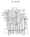
- Fig. 3 shows the device under the usual service condiction. Referring to Fig. 3, let us first describe the housing structure of the device.
- First hollow cylindrical container 50 shown at the left in the figure comprises three openings or windows: two axially aligned windows 53 and 44 (shown at the right side in the figure) formed on a side wall thereof opposing an adjacent second container 51, and a window 52 formed on a portion of the side wall thereof opposite to the window 53.
- the top and bottom ends of the container 50 are closed by a top and a bottom plate 50a and 50b, respectively.
- Second hollow cylindrical container 51 which is adjacent to the first container 50 and shown at the right in the figure, and whose top and bottom ends are closed by a top and a bottom end plate 51a and 51b, respectively, compirses two windows 54 and 45 formed in the side wall thereof opposing the windows 53 and 44 of the first container 50; the two opposing windows 53 and 54 of the first and second containers 50 and 51 are coupled in an air-tight manner to each other via an electrically insulating spacer 47B; similarly, the two opposing windows 44 and 45 are coupled in an air-tight manner to each other via an electrically insulating spacer 24.
- the second container 51 further comprises a test window 43 formed at a side opposite to the window 45, which test window 43 is closed and sealed by a closure plate 43A under usual service condition.
- the window 52 at the left of the first container 50 in the figure is coupled in an air-tight manner to a window 47 of another container (not shown) adjacent to the first container 50, via an electrically insulating spacer 47A.
- the interior spaces of the containers 50 and 51 are filled with an electrically insulating gas such as SF6 gas.
- First system of line cables (two thereof 12A and 12B are shown in Fig. 3) extends upward through the bottom end plate 50b to terminate within the first container 50; as shown schematically in Fig. 7, the first system of line cables, which usually constitutes a three phase system, comprises three line cables 12A through 12C. (In the following, however, for the sake of simplicity, reference is made only to two line cables 12A and 12B which are represented in Fig.
- the top end portions of the line cables 12A through 12C are electrically coupled, via respective detachable conductors 27A and 27B, to respective lower contacts 30A and 30B of a first disconnector having co-acting opposing contacts 34B and 33B, which are supported by and electrically coupled to the respective connection conductors 14B and 13B disposed at the upper portion within the first container 50.
- the co-acting contacts 34B and 33B are driven and translated downwardly by a driving mechanism (not shown) to be brought into electrical contact with respective opposing lower contacts 30A and 30B.
- connection conductors 14B and 13B extend through the electrically insulating spacer 47B to be electrically coupled to respective connection conductors 14D and 13D within the adjacent second container 51; similarly, toward left, the connection conductors 14B and 13B extend through the electrically insulating spacer 47A to be electrically coupled to connection conductors 14A and 13A, respectively, within an adjacent container not shown in the figure.
- a grounding device 9 mounted on a side wall of the first container 50 comprises a contact 9A which is driven by a driving mechanism (not shown) to be brought into electrical contact with contacts 27C and 27D electrically coupled to the contacts 30A and 30B of the first disconnector, so as to ground the first system of line cables 12A and 12B.
- branch conductors 26 for providing electrical connection from the first system of line cables 12A and 12B, or from the contacts 30A and 30B of the first disconnector, to test conductors, as described hereinbelow, are disposed within the first container 50. The description of the branch conductors 26 is made further below.
- second conntainer 51 The electrical organization within the second conntainer 51 is similar to that within the first container 50, except that no the branch conductors are provided.
- second system of line cables including three cables 11A through 11C as represented schematically in Fig. 7, of which two, 11A and 11B, are represented in Fig. 3, extend through the bottom end plate 51b to terminate in the second container 51.
- the top end portions of the cables 11A and 11B are coupled, via respective detachable conductors 27A and 27B, to lower contacts 31A and 31B of a second disconnector having upper co-acting contacts 34D and 33D disengageably engaging with the lower contacts 31A and 31B.
- the co-acting contacts 34D and 33D which are supported by and electrically coupled to respective connection conductors 14D and 13D, are driven by a driving mechanism (not shown) to be brought into electrical contact with respective opposing lower contacts 31A and 31B of the second disconnector.
- the grounding device 10 mounted to the side wall of the second container 51 comprises a contact 10A which is moved by a driving mechanism (not shown) to be brought into contact with the contacts 27D and 27C electrically coupled to the contacts 31A and 31B of the second disconnector, so as to ground the second system of line cables 11A and 11B.
- branch conductors 26 disposed within the first container 50 for the purpose of providing electrical connection during the test time when electrical tests are conducted on the line cables and the disconnectors.
- the branch conductors 26 (three in number in the case of three phase system) have end portions 25 supported by the electrically insulating spacer 24 between the two windows 44 and 45, and projecting therefrom into the interior of the second container 51; branch conductors 26 extend through the electrically insulating spacer 24 to be electrically coupled to respective end portions 25 thereof.
- the branch conductors 26 comprise joints so that the inner end portions thereof 26a are capable of taking two positions: a first position shown in Figs.
- test tank 19 comprises test conductors 17 supported on an end panel 18 through which outer end portions of the test conductors 17 extend. Inner end portions 17A of the test conductors 17 are capable of taking three different electrical connections:
- the end portions 17A of the test conductors 17 may be coupled, via respective intermediate conductors 17B thereof, to the end portions 25 of the branch conductors 26 which pro]ect into the second container 51, the test conductors 17 being electrically disconnected from the second system of line cables 11A and 11B and from the contacts 31A and 31B of the second disconnector.
- the branch conductors 26 are electrically coupled, as shown in Fig. 4, directly to respective first system of line cables 12A and 12B, electrical tests may be conducted on these line cables 12A and 12B.
- the end portions 17A of the test conductors 17 may be electrically coupled, via respective intermediate conductors 17B thereof, to the end portions 25 of the branch conductors 26 which project into the second container 51, the end portions 17A of the test conductors 17 being electrically connected to the second system of line cables 11A and 11B.
- the branch conductors 26 are coupled, as shown in Fig. 5, directly to respective line cables 12A and 12B of the first system of line cables, electrical tests may be conducted on the line cables 12A, 12B, 11A, and 11B.
- the end portions 17A of the test conductors 17 may be electrically coupled to the contacts 31A and 31B. Further, the branch conductors 26 may be coupled, as shown in Fig. 6, to respective contacts 31A and 31B of the second disconnector for the second system of line calbes 11A and 11B. Then, electrical tests may be conducted on the performance of the disconnectors.
- connection tank can be dispensed with according to this invention; thus, the central distance L3 between adjacent containers 50 and 51 shown in Fig. 3, and hence the installation space of the gas insulated switch device, can be minimized according to this invention.
- an electrically insulating spacer 24 between the windows 44 and 45 of the two adjacent containers 50 and 51 is not essential; namely, provided that the end portions 25 of the branch conductors 26 can be supported by some other appropriate means, the electrically insulating spacer 24 can be dispensed with.
Landscapes
- Engineering & Computer Science (AREA)
- Power Engineering (AREA)
- Gas-Insulated Switchgears (AREA)
Applications Claiming Priority (2)
| Application Number | Priority Date | Filing Date | Title |
|---|---|---|---|
| JP63316926A JPH02164210A (ja) | 1988-12-14 | 1988-12-14 | ガス絶縁開閉装置 |
| JP316926/88 | 1988-12-14 |
Publications (2)
| Publication Number | Publication Date |
|---|---|
| EP0373901A1 true EP0373901A1 (fr) | 1990-06-20 |
| EP0373901B1 EP0373901B1 (fr) | 1993-03-31 |
Family
ID=18082461
Family Applications (1)
| Application Number | Title | Priority Date | Filing Date |
|---|---|---|---|
| EP89312998A Expired - Lifetime EP0373901B1 (fr) | 1988-12-14 | 1989-12-12 | Dispositif de commutation à isolement gazeux |
Country Status (4)
| Country | Link |
|---|---|
| US (1) | US4996485A (fr) |
| EP (1) | EP0373901B1 (fr) |
| JP (1) | JPH02164210A (fr) |
| DE (1) | DE68905778T2 (fr) |
Cited By (1)
| Publication number | Priority date | Publication date | Assignee | Title |
|---|---|---|---|---|
| GB2246239A (en) * | 1990-07-19 | 1992-01-22 | Mitsubishi Electric Corp | Switching device |
Families Citing this family (3)
| Publication number | Priority date | Publication date | Assignee | Title |
|---|---|---|---|---|
| DE202006008709U1 (de) * | 2006-05-29 | 2006-08-17 | Siemens Ag | Anschlussschaltfeld für Mittelspannungsschaltanlagen |
| JP4846514B2 (ja) * | 2006-10-17 | 2011-12-28 | 株式会社東芝 | ガス絶縁開閉装置 |
| JP5627821B1 (ja) * | 2014-01-20 | 2014-11-19 | 三菱電機株式会社 | ガス絶縁開閉装置 |
Citations (2)
| Publication number | Priority date | Publication date | Assignee | Title |
|---|---|---|---|---|
| FR2418559A1 (fr) * | 1978-02-24 | 1979-09-21 | Tokyo Shibaura Electric Co | Disjoncteur de type ferme |
| EP0244630A2 (fr) * | 1986-04-01 | 1987-11-11 | Hitachi, Ltd. | Appareil de commutation à isolation gazeuse du type compact |
Family Cites Families (7)
| Publication number | Priority date | Publication date | Assignee | Title |
|---|---|---|---|---|
| JPS60249806A (ja) * | 1984-05-24 | 1985-12-10 | 日新電機株式会社 | ガス絶縁開閉装置用母線電圧変成器ユニツト |
| JPH081773B2 (ja) * | 1985-03-26 | 1996-01-10 | 三菱電機株式会社 | ガス絶縁開閉装置 |
| JPS61295802A (ja) * | 1985-06-25 | 1986-12-26 | 三菱電機株式会社 | ガス絶縁開閉装置 |
| JPS62211813A (ja) * | 1986-03-12 | 1987-09-17 | 三菱電機株式会社 | ガスブツシング |
| JP2587038B2 (ja) * | 1986-03-12 | 1997-03-05 | 三菱電機株式会社 | ガスブツシング |
| JPS6387108A (ja) * | 1986-09-29 | 1988-04-18 | 三菱電機株式会社 | ガス絶縁開閉装置 |
| JPH0767213B2 (ja) * | 1986-09-29 | 1995-07-19 | 三菱電機株式会社 | ガス絶縁開閉装置 |
-
1988
- 1988-12-14 JP JP63316926A patent/JPH02164210A/ja active Pending
-
1989
- 1989-12-12 US US07/448,859 patent/US4996485A/en not_active Expired - Fee Related
- 1989-12-12 DE DE8989312998T patent/DE68905778T2/de not_active Expired - Fee Related
- 1989-12-12 EP EP89312998A patent/EP0373901B1/fr not_active Expired - Lifetime
Patent Citations (2)
| Publication number | Priority date | Publication date | Assignee | Title |
|---|---|---|---|---|
| FR2418559A1 (fr) * | 1978-02-24 | 1979-09-21 | Tokyo Shibaura Electric Co | Disjoncteur de type ferme |
| EP0244630A2 (fr) * | 1986-04-01 | 1987-11-11 | Hitachi, Ltd. | Appareil de commutation à isolation gazeuse du type compact |
Non-Patent Citations (1)
| Title |
|---|
| B.B.C. REVIEW vol. 65, no. 4, April 1978, Baden pages 231 - 235; W.Bischofberger et al: "Circuit-Breaker Type ELK with Closing Resistors for Metalclad SF6 Installations" * |
Cited By (2)
| Publication number | Priority date | Publication date | Assignee | Title |
|---|---|---|---|---|
| GB2246239A (en) * | 1990-07-19 | 1992-01-22 | Mitsubishi Electric Corp | Switching device |
| GB2246239B (en) * | 1990-07-19 | 1994-11-30 | Mitsubishi Electric Corp | Switching device |
Also Published As
| Publication number | Publication date |
|---|---|
| JPH02164210A (ja) | 1990-06-25 |
| US4996485A (en) | 1991-02-26 |
| DE68905778T2 (de) | 1993-07-08 |
| EP0373901B1 (fr) | 1993-03-31 |
| DE68905778D1 (de) | 1993-05-06 |
Similar Documents
| Publication | Publication Date | Title |
|---|---|---|
| US6759616B2 (en) | Gas insulated switchgear | |
| US6510046B2 (en) | Gas-insulated switchgear | |
| US6538224B2 (en) | Hybrid type gas insulation switch gear apparatus | |
| US4237520A (en) | Gas insulated switch-gear apparatus | |
| US4045634A (en) | Gas insulated switch-gear apparatus | |
| JP4192470B2 (ja) | 環状母線方式のガス絶縁開閉装置 | |
| CN1113614A (zh) | 带金属外壳的气体绝缘开关装置 | |
| EP0822632B1 (fr) | Bloc de puissance pour système de distribution | |
| EP0373901B1 (fr) | Dispositif de commutation à isolement gazeux | |
| JPS60249806A (ja) | ガス絶縁開閉装置用母線電圧変成器ユニツト | |
| JPS6358008B2 (fr) | ||
| US6556428B1 (en) | Gas insulated switchgear | |
| EP0174251B1 (fr) | Appareillage de commutation à isolation gazeuse | |
| US5587873A (en) | Distributor | |
| JPH0624408B2 (ja) | ガス絶縁開閉装置 | |
| JPH0522815A (ja) | ガス絶縁開閉装置 | |
| JPH0152961B2 (fr) | ||
| JP2635700B2 (ja) | 受電用ガス絶縁変圧器盤 | |
| JPS631524Y2 (fr) | ||
| JPS638685B2 (fr) | ||
| JPS6237379Y2 (fr) | ||
| JPH0733528Y2 (ja) | ガス絶縁開閉装置 | |
| JPH0667067B2 (ja) | ガス絶縁開閉装置 | |
| EP0014224A1 (fr) | Appareillage de commutation à isolement gazeux | |
| JPH10201021A (ja) | ガス絶縁開閉装置 |
Legal Events
| Date | Code | Title | Description |
|---|---|---|---|
| PUAI | Public reference made under article 153(3) epc to a published international application that has entered the european phase |
Free format text: ORIGINAL CODE: 0009012 |
|
| AK | Designated contracting states |
Kind code of ref document: A1 Designated state(s): CH DE FR GB LI |
|
| 17P | Request for examination filed |
Effective date: 19900621 |
|
| 17Q | First examination report despatched |
Effective date: 19920701 |
|
| GRAA | (expected) grant |
Free format text: ORIGINAL CODE: 0009210 |
|
| AK | Designated contracting states |
Kind code of ref document: B1 Designated state(s): CH DE FR GB LI |
|
| REF | Corresponds to: |
Ref document number: 68905778 Country of ref document: DE Date of ref document: 19930506 |
|
| REG | Reference to a national code |
Ref country code: GB Ref legal event code: 727 |
|
| ET | Fr: translation filed | ||
| REG | Reference to a national code |
Ref country code: GB Ref legal event code: 727A |
|
| REG | Reference to a national code |
Ref country code: GB Ref legal event code: 727B |
|
| PLBE | No opposition filed within time limit |
Free format text: ORIGINAL CODE: 0009261 |
|
| STAA | Information on the status of an ep patent application or granted ep patent |
Free format text: STATUS: NO OPPOSITION FILED WITHIN TIME LIMIT |
|
| 26N | No opposition filed | ||
| PGFP | Annual fee paid to national office [announced via postgrant information from national office to epo] |
Ref country code: CH Payment date: 19941214 Year of fee payment: 6 |
|
| PGFP | Annual fee paid to national office [announced via postgrant information from national office to epo] |
Ref country code: GB Payment date: 19951204 Year of fee payment: 7 |
|
| REG | Reference to a national code |
Ref country code: GB Ref legal event code: 746 Effective date: 19951106 |
|
| PGFP | Annual fee paid to national office [announced via postgrant information from national office to epo] |
Ref country code: FR Payment date: 19951212 Year of fee payment: 7 |
|
| PGFP | Annual fee paid to national office [announced via postgrant information from national office to epo] |
Ref country code: DE Payment date: 19951214 Year of fee payment: 7 |
|
| PG25 | Lapsed in a contracting state [announced via postgrant information from national office to epo] |
Ref country code: LI Effective date: 19951231 Ref country code: CH Effective date: 19951231 |
|
| REG | Reference to a national code |
Ref country code: FR Ref legal event code: D6 |
|
| REG | Reference to a national code |
Ref country code: CH Ref legal event code: PL |
|
| PG25 | Lapsed in a contracting state [announced via postgrant information from national office to epo] |
Ref country code: GB Effective date: 19961212 |
|
| GBPC | Gb: european patent ceased through non-payment of renewal fee |
Effective date: 19961212 |
|
| PG25 | Lapsed in a contracting state [announced via postgrant information from national office to epo] |
Ref country code: FR Effective date: 19970829 |
|
| PG25 | Lapsed in a contracting state [announced via postgrant information from national office to epo] |
Ref country code: DE Effective date: 19970902 |
|
| REG | Reference to a national code |
Ref country code: FR Ref legal event code: ST |