EP0373964A2 - Correction pour la composition d'un fluide traversant un débitmètre - Google Patents
Correction pour la composition d'un fluide traversant un débitmètre Download PDFInfo
- Publication number
- EP0373964A2 EP0373964A2 EP89313165A EP89313165A EP0373964A2 EP 0373964 A2 EP0373964 A2 EP 0373964A2 EP 89313165 A EP89313165 A EP 89313165A EP 89313165 A EP89313165 A EP 89313165A EP 0373964 A2 EP0373964 A2 EP 0373964A2
- Authority
- EP
- European Patent Office
- Prior art keywords
- fluid
- flow
- interest
- microanemometer
- obtaining
- Prior art date
- Legal status (The legal status is an assumption and is not a legal conclusion. Google has not performed a legal analysis and makes no representation as to the accuracy of the status listed.)
- Granted
Links
Images



Classifications
-
- G—PHYSICS
- G01—MEASURING; TESTING
- G01F—MEASURING VOLUME, VOLUME FLOW, MASS FLOW OR LIQUID LEVEL; METERING BY VOLUME
- G01F1/00—Measuring the volume flow or mass flow of fluid or fluent solid material wherein the fluid passes through a meter in a continuous flow
- G01F1/68—Measuring the volume flow or mass flow of fluid or fluent solid material wherein the fluid passes through a meter in a continuous flow by using thermal effects
- G01F1/696—Circuits therefor, e.g. constant-current flow meters
- G01F1/6965—Circuits therefor, e.g. constant-current flow meters comprising means to store calibration data for flow signal calculation or correction
-
- G—PHYSICS
- G01—MEASURING; TESTING
- G01F—MEASURING VOLUME, VOLUME FLOW, MASS FLOW OR LIQUID LEVEL; METERING BY VOLUME
- G01F1/00—Measuring the volume flow or mass flow of fluid or fluent solid material wherein the fluid passes through a meter in a continuous flow
- G01F1/68—Measuring the volume flow or mass flow of fluid or fluent solid material wherein the fluid passes through a meter in a continuous flow by using thermal effects
-
- G—PHYSICS
- G01—MEASURING; TESTING
- G01F—MEASURING VOLUME, VOLUME FLOW, MASS FLOW OR LIQUID LEVEL; METERING BY VOLUME
- G01F1/00—Measuring the volume flow or mass flow of fluid or fluent solid material wherein the fluid passes through a meter in a continuous flow
- G01F1/68—Measuring the volume flow or mass flow of fluid or fluent solid material wherein the fluid passes through a meter in a continuous flow by using thermal effects
- G01F1/684—Structural arrangements; Mounting of elements, e.g. in relation to fluid flow
- G01F1/6842—Structural arrangements; Mounting of elements, e.g. in relation to fluid flow with means for influencing the fluid flow
-
- G—PHYSICS
- G01—MEASURING; TESTING
- G01F—MEASURING VOLUME, VOLUME FLOW, MASS FLOW OR LIQUID LEVEL; METERING BY VOLUME
- G01F1/00—Measuring the volume flow or mass flow of fluid or fluent solid material wherein the fluid passes through a meter in a continuous flow
- G01F1/76—Devices for measuring mass flow of a fluid or a fluent solid material
- G01F1/86—Indirect mass flowmeters, e.g. measuring volume flow and density, temperature or pressure
-
- G—PHYSICS
- G01—MEASURING; TESTING
- G01F—MEASURING VOLUME, VOLUME FLOW, MASS FLOW OR LIQUID LEVEL; METERING BY VOLUME
- G01F15/00—Details of, or accessories for, apparatus of groups G01F1/00 - G01F13/00 insofar as such details or appliances are not adapted to particular types of such apparatus
- G01F15/02—Compensating or correcting for variations in pressure, density or temperature
- G01F15/04—Compensating or correcting for variations in pressure, density or temperature of gases to be measured
- G01F15/043—Compensating or correcting for variations in pressure, density or temperature of gases to be measured using electrical means
Definitions
- the present invention relates to fluid flow measurement and, more particularly, addresses overcoming inaccuracies in flow measurement.
- the invention eliminates errors in mass and volumetric flow rates measured for gaseous fluids with respect to compositional changes in the fluid of interest.
- Hot film microanemometer packages for general use are known for both uni- and bi-directional flow applications.
- An example of such a device is illustrated and described in U.S. Patent 4,501,144 to Higashi et al.
- the microanemometers or "microbridges" themselves are quite inexpensive to produce.
- microanemometers are capable of quite accurate flow sensing when directly exposed to a stream of fluid flowing past, especially if such flow is laminar. In this manner such a sensor can be used to directly measure the dynamic flow characteristics of the fluid.
- nulled flow i.e., the flow signal corrected by subtracting the value corresponding to the signal obtained at zero flow
- fluid properties including specific heat, cp, thermal conductivity, k, and density, q.
- nulled sensor output i.e., the voltaic sensor signal or other related electrical measurement nulled by subtracting the value obtained at zero flow
- cp, k, and q certain similar relationships exist between (1) the nulled sensor output, i.e., the voltaic sensor signal or other related electrical measurement nulled by subtracting the value obtained at zero flow
- correction factors are individual with respect to gas composition and all sensor output vs. flow (mass or volumetric) curves obtained for different individual gas species are equal except for the individual constant factors.
- the present invention makes use of a second microanemometer sensor not directly exposed to the flowing fluid, but in more remote communication with that fluid that can be used to measure certain parameters related to the fluid which require a more static environment.
- a second microanemometer sensor is used for the direct measurement of thermal conductivity, k, and specific heat, c P , in accordance with a known technique which allows the accurate determination of both properties in a sample of interest using a single sensing system. In addition these properties allow the determination of the density, or q.
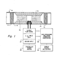
- Figure 1 depicts one embodiment of a flowmeter utilizing the concept of the present invention.
- the system is depicted as an integral part of a length of pipe, as a pipe, as a gas pipe, or other conduit or meter body member 10 which can easily be adapted to fit into almost any existing piping scheme as between a pair of spaced unions, couplings or the like.
- the basic system includes a pair of filter members 11 and 12 flanking a capillary system which includes means for reducing the conduit diameter at 13 and 14 in conjunction with accessing a split bundle containing parts 15 and 16 of capillary tubes.
- the reducing sections 13 and 14 create a plenum effect to reduce pressure losses in conjunction with entry and exit of the fluid to the capillary bundle. This, in turn, reduces overall system pressure drop and velocity head effect.
- a microbridge or microanemometer sensor package for sensing flow through the system is depicted generally at 17. It contains individual microbridge sensors 18 and 18a for dynamic and static fluid sensing respectively. Electrical connections, pins represented by 19, connect the microanemometer to a source of power for the heater or heaters shown by block 20 and external signal receiving means 21 and accompanying signal and data processing means 22 to interpret the output.
- the desired output may take any suitable form or display and is represented by block 23.
- the remote or static microbridge or microanemometer 18a communicates with the flowing fluid of interest via an opening in the meter member 24 in the sensor package 17 such that a representative composition is observed in what is basically a static environment with respect to flow. Because compositional changes in the flowing fluid of interest occur relatively slowly in comparison to flow velocities, the response of the remote microbridge sensor remains timely.
- microbridge semiconductor chip sensors such as those depicted by reference numerals 18 and 18a
- etched semiconductor microbridges are used as condition or flow sensors.
- Such sensors might include, for example, a pair of thin film sensors flanking a thin film heater.
- Semiconductor chip sensors of the class described are treated in a more detailed manner in one or more of patents such as 4,478,076, 4,478,077, 4,501,144, 4,555,939, 4,651,564 and 4,683,159 all of common assignee with the present invention. To the extent necessary additional details with respect to the microbridge sensors may be incorporated by reference from these cited documents.
- the dynamic flow sensor 18 comprises a pair of thin film sensors symmetrically flanking a thin film heater, for example, the sensor can be used to sense flow in either direction. That is, of course, provided that the chip assembly positions the sensor in the proper orientation so that the flow meets the microbridge at a right angle in the assembled meter. This further allows the flowmeter system of the present invention to be reversible with respect to the conduit system of the fluid of interest as it is then quite laterally symmetrical.
- the sensor 18 then, is directly exposed to the stream of fluid flowing past it in the conduit. This sensor is used to directly measure the dynamic flow characteristics of the fluid.
- the second microanemometer sensor 18a which may be mounted back-to-back with the sensor 18, as illustrated in Figure 1, enables other parameters of the fluid to be measured simultaneously with the dynamic flow. As stated above, while the sensor 18a is not directly exposed to the flowing fluid, it is in direct communication with that fluid and can be used to measure certain parameters related to the fluid which are facilitated by a more static environment.
- Such a sensor can be used for the direct measurement of thermal conductivity, k, and specific heat, cp, in accordance with a technique which allows the accurate determination of both properties and a sample of interest using a single sensing system. That technique contemplates generating an energy or temperature pulse in one or more heater elements disposed in and closely coupled to the fluid medium of interest. Characteristic values of k and cp of the fluid of interest then cause corresponding changes in the time variable temperature response of the heater to the pulse. Under relatively static sample flow conditions this, in turn, induces corresponding changes in the time variable response of or more temperature responsive sensors coupled to the heater principally via the fluid medium of interest.
- the thermal pulse of this source need be only of sufficient duration that the heater achieve a substantially steady-state temperature for a short time.
- This pulse produces both steady-state and transient conditions in the sensor.
- Thermal conductivity, k, and specific heat, cp can be sensed within the same sensed thermal pulse by using a steady-state temperature plateau to determine k, which is then used with the rate of change temperature in the transient condition to determine cp.
- Such a system is described in greater detail in co-pending application serial no. 210,892, filed June 24, 1988 and assigned the same assignee as the present application.
- Figure 2 shows the nulled sensor output plotted vs. nulled mass flow for six different gasses.
- the same mass flow of any fluid of interest should produce the same output voltage, i.e., all curves should coincide.
- the raw or uncorrected data shows considerable deviation among the various gases.
- Figure 3 represents the data of Figure 2 plotted as log-log functions. There the signal output is shown in terms of nulled sensor resistance rather than voltage output to expand the vertical axis.
- Figure 3 demonstrates the disparities of Figure 2 somewhat more dramatically, especially at the lower flow rates, i.e., ⁇ 100 mg/min. In some cases discrepancies or errors of as much 100% or more occur at low flow rates for a given sensor output.
- the data of Figures 2 and 3 were obtained by operating the flow sensor heater at constant temperature or temperature rise above the ambient temperature.
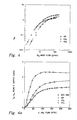
- Figures 4 and 4a are noteworthy because it illustrates certain similarities which have been found to exist among the gases involved in the mass flow measurements.
- the curves, while not congruent, are strikingly similar in shape indicating some type of parallel shift especially when plotted on a log-log plot as in Figure 4. This view is not as evident in the linear-linear plot of Figure 4a.
- Complete congruency indicates consistent, error-free measurement.
- the similarity in shape of the nulled measurements indicates that a constant correction factor might be possible for each gas if the basis of or reasons for the variation in readings among the species were known.
- shift correction factors in the form of simple, constant factors for each gas have been found to equilibrate mass or volumetric flow measurements with sensor output. This has been accomplished by using factors derived from the individual gas properties like k, cp, and q. Additional factors may be used depending on the required accuracy of the corrected signal.
- subscript (o) refers to the base or reference gas.
- the reference gas is methane.
- Figure 7 depicts a corrected version of Figure 3 also using CH4 as the reference gas.
- the microbridge heater was operated in a constant temperature mode rather than at constant current input.
- So was not corrected and an additional factor with respect to density, q/q o was also used.
- Figure 8 depicts another solution or corrected version of Figures 2 or 3 in which the sensor is also operated in a constant temperature mode and the sensor output is uncorrected.
- This solution differs from that of Figure 7 only in the elimination of the density factor, q/q o . It does show some discrepancy with respect to He which is understood of in terms of its very different k and cp properties.
- Another aspect of the present invention comprises the utilisation of data from the composition correction technique in order to derive a measurement of the energy value for the gas flow. For example, having determined the composition of the gas flow during a measurement, and being aware of the calorific and other characteristics of the constituents of the mixture as determined, it is readily feasible to derive the energy value of the gas flow at that instant, and hence with appropriate summation or integration over time, measurement of the total energy content supplied can readily be achieved.
- the present invention embodies methods of determining the energy value of gas flows, particularly utilising composition correction techniques as described hereinbefore, and also embodies means to implement such methods.
Landscapes
- Physics & Mathematics (AREA)
- Fluid Mechanics (AREA)
- General Physics & Mathematics (AREA)
- Measuring Volume Flow (AREA)
- Details Of Flowmeters (AREA)
- Organic Low-Molecular-Weight Compounds And Preparation Thereof (AREA)
Applications Claiming Priority (2)
| Application Number | Priority Date | Filing Date | Title |
|---|---|---|---|
| US07/285,897 US4961348A (en) | 1988-12-16 | 1988-12-16 | Flowmeter fluid composition correction |
| US285897 | 1988-12-16 |
Publications (3)
| Publication Number | Publication Date |
|---|---|
| EP0373964A2 true EP0373964A2 (fr) | 1990-06-20 |
| EP0373964A3 EP0373964A3 (en) | 1990-11-07 |
| EP0373964B1 EP0373964B1 (fr) | 1995-01-25 |
Family
ID=23096150
Family Applications (1)
| Application Number | Title | Priority Date | Filing Date |
|---|---|---|---|
| EP89313165A Expired - Lifetime EP0373964B1 (fr) | 1988-12-16 | 1989-12-15 | Correction pour la composition d'un fluide traversant un débitmètre |
Country Status (6)
| Country | Link |
|---|---|
| US (1) | US4961348A (fr) |
| EP (1) | EP0373964B1 (fr) |
| JP (1) | JPH02221817A (fr) |
| AT (1) | ATE117794T1 (fr) |
| CA (1) | CA2000029C (fr) |
| DE (1) | DE68920847T2 (fr) |
Cited By (5)
| Publication number | Priority date | Publication date | Assignee | Title |
|---|---|---|---|---|
| WO1991006809A1 (fr) * | 1989-10-30 | 1991-05-16 | Honeywell Inc. | Commande de combustion a micropont |
| GB2263776A (en) * | 1992-01-28 | 1993-08-04 | Endress & Hauser Ltd | Fluid mass flowmeter |
| WO1995018958A1 (fr) * | 1994-01-10 | 1995-07-13 | Siemens Aktiengesellschaft | Procede pour la determination du debit volumetrique d'un gaz dans un tube de mesure |
| US6308553B1 (en) | 1999-06-04 | 2001-10-30 | Honeywell International Inc | Self-normalizing flow sensor and method for the same |
| DE102013006397B4 (de) | 2012-05-22 | 2023-06-29 | Abb Schweiz Ag | Thermischer Durchflussmesser und Verfahren zum Betrieb desselben |
Families Citing this family (32)
| Publication number | Priority date | Publication date | Assignee | Title |
|---|---|---|---|---|
| US5237523A (en) * | 1990-07-25 | 1993-08-17 | Honeywell Inc. | Flowmeter fluid composition and temperature correction |
| US5321992A (en) * | 1991-09-26 | 1994-06-21 | Dxl Usa | Measurement of gas flows with enhanced accuracy |
| EP0554095A3 (en) * | 1992-01-30 | 1994-12-14 | Honeywell Inc | Determination of fuel characteristics |
| DE4236559A1 (de) * | 1992-10-02 | 1994-04-07 | Kobold Klaus | Verfahren zum Kalibrieren eines kalorimetrischen Strömungwächters |
| US5723783A (en) * | 1994-03-15 | 1998-03-03 | J & W Scientific, Incorporated | Acoustic displacement flowmeter |
| US6019505A (en) * | 1997-12-31 | 2000-02-01 | Honeywell Inc. | Time lag approach for measuring thermal conductivity and specific heat |
| US6223593B1 (en) | 1997-12-31 | 2001-05-01 | Honeywell International Inc. | Self-oscillating fluid sensor |
| US6169965B1 (en) | 1997-12-31 | 2001-01-02 | Honeywell International Inc. | Fluid property and flow sensing via a common frequency generator and FFT |
| US6079253A (en) * | 1997-12-31 | 2000-06-27 | Honeywell Inc. | Method and apparatus for measuring selected properties of a fluid of interest using a single heater element |
| US6234016B1 (en) | 1997-12-31 | 2001-05-22 | Honeywell International Inc. | Time lag approach for measuring fluid velocity |
| US6152177A (en) * | 1999-10-13 | 2000-11-28 | Systec Inc. | Method and apparatus for auto-zeroing a flow sensor |
| US6502459B1 (en) | 2000-09-01 | 2003-01-07 | Honeywell International Inc. | Microsensor for measuring velocity and angular direction of an incoming air stream |
| US6450024B1 (en) * | 2001-03-07 | 2002-09-17 | Delta M Corporation | Flow sensing device |
| JP2004093170A (ja) * | 2002-08-29 | 2004-03-25 | Tokyo Gas Co Ltd | 整流装置 |
| US7647844B2 (en) * | 2003-07-11 | 2010-01-19 | Mitsui Mining & Smelting Co., Ltd. | Device and method of detecting flow rate/liquid kind, and device and method of detecting liquid kind |
| EP1653227B1 (fr) * | 2003-07-11 | 2017-10-25 | SUN-A Corporation | Dispositif et procede de detection de type de liquide |
| WO2006020870A1 (fr) * | 2004-08-13 | 2006-02-23 | Entegris, Inc. | Systeme et procede d'etalonnage d'un dispositif d'ecoulement |
| DE102005053096B4 (de) * | 2005-11-04 | 2020-01-30 | Endress + Hauser Wetzer Gmbh + Co Kg | Verfahren zur Kalibration eines kalorimetrischen Durchflussmessgerätes und entsprechende Vorrichtung |
| DE102005057688A1 (de) * | 2005-12-01 | 2007-06-14 | Endress + Hauser Flowtec Ag | Vorrichtung zur Bestimmung und/oder Überwachung des Massedurchflusses eines gasförmigen Mediums |
| JP5066675B2 (ja) * | 2006-07-05 | 2012-11-07 | Smc株式会社 | フローセンサ |
| CN101126652B (zh) * | 2007-09-29 | 2011-03-30 | 重庆前卫仪表厂 | 电子式质量流量燃气计量表 |
| JP2009162128A (ja) * | 2008-01-08 | 2009-07-23 | Yamatake Corp | 燃料供給装置 |
| JP5107063B2 (ja) * | 2008-01-08 | 2012-12-26 | アズビル株式会社 | 流量制御装置 |
| EP2175246B1 (fr) | 2008-10-09 | 2017-07-19 | Sensirion AG | Procédé de mesure d'un paramètre de la composition d'un fluide au moyen d'un capteur de débit |
| EP2204555B1 (fr) * | 2009-01-02 | 2011-08-03 | Sensirion AG | Système de stockage d'ammoniac |
| US8434479B2 (en) | 2009-02-27 | 2013-05-07 | Covidien Lp | Flow rate compensation for transient thermal response of hot-wire anemometers |
| US8113046B2 (en) * | 2010-03-22 | 2012-02-14 | Honeywell International Inc. | Sensor assembly with hydrophobic filter |
| EP2392898B1 (fr) | 2010-06-04 | 2017-12-13 | Sensirion AG | Système de détection |
| DE102011075519A1 (de) * | 2011-05-09 | 2012-11-15 | Innovative Sensor Technology Ist Ag | Verfahren und Vorrichtung zum thermischen Bestimmen des Massedurchflusses eines Mediums in einer Leitung |
| DE102011051931A1 (de) * | 2011-07-19 | 2013-01-24 | Aixtron Se | Vorrichtung und Verfahren zum Bestimmen des Dampfdrucks eines in einem Trägergasstrom verdampften Ausgangsstoffes |
| DE202013103647U1 (de) | 2013-08-12 | 2013-09-02 | Aspect Imaging Ltd. | Ein System zum Online-Messen und Steuern von O2-Fraktion, CO-Fraktion und CO2-Fraktion |
| WO2025158824A1 (fr) * | 2024-01-23 | 2025-07-31 | ミツミ電機株式会社 | Capteur de débit et programme |
Family Cites Families (18)
| Publication number | Priority date | Publication date | Assignee | Title |
|---|---|---|---|---|
| US1769358A (en) * | 1922-04-01 | 1930-07-01 | Cutler Hammer Inc | Method of and apparatus for ascertaining the rate of flow of fluids |
| DE1232358B (de) * | 1962-07-26 | 1967-01-12 | Licentia Gmbh | Verfahren und Durchfuehrungsanordnungen zur selbsttaetigen Durchfuehrung der durch den Feuchtigkeitsgehalt erforderlichen Korrektur eines gemessenen Gasvolumenwertes |
| NL6618236A (fr) * | 1966-12-28 | 1968-07-01 | ||
| US3891391A (en) * | 1973-05-14 | 1975-06-24 | George R Boone | Fluid flow measuring system using improved temperature compensation apparatus and method |
| JPS5810610A (ja) * | 1981-07-13 | 1983-01-21 | Yokogawa Hokushin Electric Corp | 電磁流量計 |
| US4478077A (en) * | 1982-09-30 | 1984-10-23 | Honeywell Inc. | Flow sensor |
| US4501144A (en) * | 1982-09-30 | 1985-02-26 | Honeywell Inc. | Flow sensor |
| US4683159A (en) * | 1982-09-30 | 1987-07-28 | Honeywell Inc. | Semiconductor device structure and processing |
| US4651564A (en) * | 1982-09-30 | 1987-03-24 | Honeywell Inc. | Semiconductor device |
| US4478076A (en) * | 1982-09-30 | 1984-10-23 | Honeywell Inc. | Flow sensor |
| US4487063A (en) * | 1983-07-11 | 1984-12-11 | General Motors Corporation | Solid state mass air flow sensor |
| US4555939A (en) * | 1984-03-19 | 1985-12-03 | Honeywell Inc. | Condition responsive sensor for fluid flow measurement |
| US4599895A (en) * | 1984-07-12 | 1986-07-15 | Wiseman Donald F | Method and apparatus for measuring fluid flow |
| JPS61164117A (ja) * | 1985-01-16 | 1986-07-24 | Yokogawa Electric Corp | 気体流量測定装置 |
| US4685311A (en) * | 1985-12-09 | 1987-08-11 | Leitner Corporation | Food preparation table having a refrigerated ingredient zone |
| JPH06103211B2 (ja) * | 1987-05-19 | 1994-12-14 | 日産自動車株式会社 | 機関の空気量検出装置 |
| GB8719105D0 (en) * | 1987-08-12 | 1987-09-16 | Schlumberger Electronics Uk | Fluid metering |
| GB8720356D0 (en) * | 1987-08-28 | 1987-10-07 | Thorn Emi Flow Measurement Ltd | Fluid meter |
-
1988
- 1988-12-16 US US07/285,897 patent/US4961348A/en not_active Expired - Lifetime
-
1989
- 1989-10-02 CA CA002000029A patent/CA2000029C/fr not_active Expired - Lifetime
- 1989-12-14 JP JP1324836A patent/JPH02221817A/ja active Pending
- 1989-12-15 EP EP89313165A patent/EP0373964B1/fr not_active Expired - Lifetime
- 1989-12-15 AT AT89313165T patent/ATE117794T1/de not_active IP Right Cessation
- 1989-12-15 DE DE68920847T patent/DE68920847T2/de not_active Expired - Fee Related
Cited By (10)
| Publication number | Priority date | Publication date | Assignee | Title |
|---|---|---|---|---|
| WO1991006809A1 (fr) * | 1989-10-30 | 1991-05-16 | Honeywell Inc. | Commande de combustion a micropont |
| GB2263776A (en) * | 1992-01-28 | 1993-08-04 | Endress & Hauser Ltd | Fluid mass flowmeter |
| GB2263776B (en) * | 1992-01-28 | 1995-05-17 | Endress & Hauser Ltd | Fluid mass flowmeter |
| WO1995018958A1 (fr) * | 1994-01-10 | 1995-07-13 | Siemens Aktiengesellschaft | Procede pour la determination du debit volumetrique d'un gaz dans un tube de mesure |
| US6308553B1 (en) | 1999-06-04 | 2001-10-30 | Honeywell International Inc | Self-normalizing flow sensor and method for the same |
| US6553808B2 (en) | 1999-06-04 | 2003-04-29 | Honeywell International Inc. | Self-normalizing flow sensor and method for the same |
| US6715339B2 (en) | 1999-06-04 | 2004-04-06 | Honeywell International Inc. | Self-normalizing flow sensor and method for the same |
| WO2002014797A1 (fr) * | 2000-01-10 | 2002-02-21 | Honeywell International Inc. | Capteur de debit auto-regularisant et procede pour la mise en oeuvre dudit capteur |
| AU773865B2 (en) * | 2000-01-10 | 2004-06-10 | Honeywell International, Inc. | Self-normalizing flow sensor and method for the same |
| DE102013006397B4 (de) | 2012-05-22 | 2023-06-29 | Abb Schweiz Ag | Thermischer Durchflussmesser und Verfahren zum Betrieb desselben |
Also Published As
| Publication number | Publication date |
|---|---|
| EP0373964B1 (fr) | 1995-01-25 |
| EP0373964A3 (en) | 1990-11-07 |
| DE68920847T2 (de) | 1995-07-06 |
| US4961348A (en) | 1990-10-09 |
| CA2000029A1 (fr) | 1990-06-16 |
| DE68920847D1 (de) | 1995-03-09 |
| CA2000029C (fr) | 1999-12-14 |
| ATE117794T1 (de) | 1995-02-15 |
| JPH02221817A (ja) | 1990-09-04 |
Similar Documents
| Publication | Publication Date | Title |
|---|---|---|
| EP0373964B1 (fr) | Correction pour la composition d'un fluide traversant un débitmètre | |
| US4885938A (en) | Flowmeter fluid composition correction | |
| US5237523A (en) | Flowmeter fluid composition and temperature correction | |
| Yavuzkurt | A guide to uncertainty analysis of hot-wire data | |
| Collis et al. | Two-dimensional convection from heated wires at low Reynolds numbers | |
| Fujita et al. | Measurement of Reynolds stress by a single rotated hot wire anemometer | |
| EP0435611B1 (fr) | Capteur de pression absolue, résistant à la surpression | |
| US4080837A (en) | Sonic measurement of flow rate and water content of oil-water streams | |
| Walker et al. | Molecular Diffusion Studies in Gases at High Temperature. I. The``Point Source''Technique | |
| Bruun et al. | Velocity calibration relationships for hot-wire anemometry | |
| EP0608514A2 (fr) | Correcteur d'écoulement volumétrique et méthode associée | |
| CN114777863A (zh) | 一种多组分气体流量补偿装置及补偿方法 | |
| Aumanand et al. | A novel method of using a control valve for measurement and control of flow | |
| Hayakawa et al. | Development of a transfer standard with sonic Venturi nozzles for small mass flow rates of gases | |
| CN115165961A (zh) | 一种气体定压比热容测量装置及其测量方法 | |
| US4237904A (en) | Medical apparatus for the measurement of respiratory flow independent of gaseous composition | |
| Wigertz | A low-resistance flow meter for wide-range ventilatory measurement | |
| US3060737A (en) | Method of measuring the flow of fluids of variable composition | |
| US4761744A (en) | Method and device for determining heats of combustion of gaseous hydrocarbons | |
| US12613175B2 (en) | Method and device for determining a flow rate | |
| Cherrett | Temperature error compensation applied to pressure measurements taken with miniature semiconductor pressure transducers in a high-speed research compressor | |
| Yu et al. | Microchannel pyroelectric anemometer | |
| JP2534418B2 (ja) | 熱量計 | |
| US6382024B1 (en) | Thermocouple boundary layer rake | |
| US20230266219A1 (en) | Capillary Viscometer |
Legal Events
| Date | Code | Title | Description |
|---|---|---|---|
| PUAI | Public reference made under article 153(3) epc to a published international application that has entered the european phase |
Free format text: ORIGINAL CODE: 0009012 |
|
| AK | Designated contracting states |
Kind code of ref document: A2 Designated state(s): AT BE CH DE ES FR GB IT LI NL |
|
| PUAL | Search report despatched |
Free format text: ORIGINAL CODE: 0009013 |
|
| AK | Designated contracting states |
Kind code of ref document: A3 Designated state(s): AT BE CH DE ES FR GB IT LI NL |
|
| RHK1 | Main classification (correction) |
Ipc: G01F 15/14 |
|
| 17P | Request for examination filed |
Effective date: 19910425 |
|
| 17Q | First examination report despatched |
Effective date: 19921218 |
|
| GRAA | (expected) grant |
Free format text: ORIGINAL CODE: 0009210 |
|
| AK | Designated contracting states |
Kind code of ref document: B1 Designated state(s): AT BE CH DE ES FR GB IT LI NL |
|
| PG25 | Lapsed in a contracting state [announced via postgrant information from national office to epo] |
Ref country code: IT Free format text: LAPSE BECAUSE OF FAILURE TO SUBMIT A TRANSLATION OF THE DESCRIPTION OR TO PAY THE FEE WITHIN THE PRE;WARNING: LAPSES OF ITALIAN PATENTS WITH EFFECTIVE DATE BEFORE 2007 MAY HAVE OCCURRED AT ANY TIME BEFORE 2007. THE CORRECT EFFECTIVE DATE MAY BE DIFFERENT FROM THE ONE RECORDED.SCRIBED TIME-LIMIT Effective date: 19950125 Ref country code: ES Free format text: THE PATENT HAS BEEN ANNULLED BY A DECISION OF A NATIONAL AUTHORITY Effective date: 19950125 Ref country code: BE Effective date: 19950125 Ref country code: LI Effective date: 19950125 Ref country code: NL Effective date: 19950125 Ref country code: AT Effective date: 19950125 Ref country code: CH Effective date: 19950125 |
|
| REF | Corresponds to: |
Ref document number: 117794 Country of ref document: AT Date of ref document: 19950215 Kind code of ref document: T |
|
| REF | Corresponds to: |
Ref document number: 68920847 Country of ref document: DE Date of ref document: 19950309 |
|
| ET | Fr: translation filed | ||
| REG | Reference to a national code |
Ref country code: CH Ref legal event code: PL |
|
| NLV1 | Nl: lapsed or annulled due to failure to fulfill the requirements of art. 29p and 29m of the patents act | ||
| PLBE | No opposition filed within time limit |
Free format text: ORIGINAL CODE: 0009261 |
|
| STAA | Information on the status of an ep patent application or granted ep patent |
Free format text: STATUS: NO OPPOSITION FILED WITHIN TIME LIMIT |
|
| 26N | No opposition filed | ||
| REG | Reference to a national code |
Ref country code: GB Ref legal event code: IF02 |
|
| PGFP | Annual fee paid to national office [announced via postgrant information from national office to epo] |
Ref country code: GB Payment date: 20071106 Year of fee payment: 19 |
|
| PGFP | Annual fee paid to national office [announced via postgrant information from national office to epo] |
Ref country code: DE Payment date: 20071228 Year of fee payment: 19 |
|
| PGFP | Annual fee paid to national office [announced via postgrant information from national office to epo] |
Ref country code: FR Payment date: 20071204 Year of fee payment: 19 |
|
| GBPC | Gb: european patent ceased through non-payment of renewal fee |
Effective date: 20081215 |
|
| REG | Reference to a national code |
Ref country code: FR Ref legal event code: ST Effective date: 20090831 |
|
| PG25 | Lapsed in a contracting state [announced via postgrant information from national office to epo] |
Ref country code: DE Free format text: LAPSE BECAUSE OF NON-PAYMENT OF DUE FEES Effective date: 20090701 |
|
| PG25 | Lapsed in a contracting state [announced via postgrant information from national office to epo] |
Ref country code: GB Free format text: LAPSE BECAUSE OF NON-PAYMENT OF DUE FEES Effective date: 20081215 |
|
| PG25 | Lapsed in a contracting state [announced via postgrant information from national office to epo] |
Ref country code: FR Free format text: LAPSE BECAUSE OF NON-PAYMENT OF DUE FEES Effective date: 20081231 |