EP0374326A1 - Audio-Rauschsperre - Google Patents
Audio-Rauschsperre Download PDFInfo
- Publication number
- EP0374326A1 EP0374326A1 EP88312266A EP88312266A EP0374326A1 EP 0374326 A1 EP0374326 A1 EP 0374326A1 EP 88312266 A EP88312266 A EP 88312266A EP 88312266 A EP88312266 A EP 88312266A EP 0374326 A1 EP0374326 A1 EP 0374326A1
- Authority
- EP
- European Patent Office
- Prior art keywords
- audio
- circuit
- set forth
- noise gate
- gate
- Prior art date
- Legal status (The legal status is an assumption and is not a legal conclusion. Google has not performed a legal analysis and makes no representation as to the accuracy of the status listed.)
- Withdrawn
Links
- 230000005236 sound signal Effects 0.000 claims abstract description 36
- 238000001514 detection method Methods 0.000 claims abstract description 10
- 239000003990 capacitor Substances 0.000 claims description 20
- 230000008878 coupling Effects 0.000 claims description 7
- 238000010168 coupling process Methods 0.000 claims description 7
- 238000005859 coupling reaction Methods 0.000 claims description 7
- 238000000034 method Methods 0.000 claims description 4
- 230000002459 sustained effect Effects 0.000 claims description 3
- 239000004065 semiconductor Substances 0.000 claims 1
- 230000005669 field effect Effects 0.000 description 22
- 238000010586 diagram Methods 0.000 description 10
- 238000001228 spectrum Methods 0.000 description 6
- 230000000694 effects Effects 0.000 description 3
- 238000005086 pumping Methods 0.000 description 2
- 230000035945 sensitivity Effects 0.000 description 2
- 238000001914 filtration Methods 0.000 description 1
- 238000005286 illumination Methods 0.000 description 1
- 230000001629 suppression Effects 0.000 description 1
Images

Classifications
-
- H—ELECTRICITY
- H03—ELECTRONIC CIRCUITRY
- H03G—CONTROL OF AMPLIFICATION
- H03G5/00—Tone control or bandwidth control in amplifiers
- H03G5/16—Automatic control
- H03G5/18—Automatic control in untuned amplifiers
-
- H—ELECTRICITY
- H03—ELECTRONIC CIRCUITRY
- H03G—CONTROL OF AMPLIFICATION
- H03G5/00—Tone control or bandwidth control in amplifiers
- H03G5/16—Automatic control
- H03G5/18—Automatic control in untuned amplifiers
- H03G5/22—Automatic control in untuned amplifiers having semiconductor devices
-
- H—ELECTRICITY
- H04—ELECTRIC COMMUNICATION TECHNIQUE
- H04B—TRANSMISSION
- H04B1/00—Details of transmission systems, not covered by a single one of groups H04B3/00 - H04B13/00; Details of transmission systems not characterised by the medium used for transmission
- H04B1/06—Receivers
- H04B1/10—Means associated with receiver for limiting or suppressing noise or interference
- H04B1/1027—Means associated with receiver for limiting or suppressing noise or interference assessing signal quality or detecting noise/interference for the received signal
Definitions
- the present invention relates in general to an audio noise gate and pertains, more particularly, to a noise gate that automatically removes high frequency noise.
- Another object of the present invention is to provide an improved high frequency noise gate that is adapted to roll-off the upper portion of the audio spectrum, say above 1.5 KHz when no high frequencies are present in the audio signal.
- a further object of the present invention is to provide an improved high frequency noise gate the will not only minimize compressor hiss pumping at high sustain settings, but will also assist in removing hiss and buzz from single coil pick-ups or any other special effects devices.
- Still another object of the present invention is to provide a high frequency noise gate that is adapted to automatically turn off hiss at a relatively slow rate (slow release time) when notes are held and that furthermore turns off the hiss quickly when notes are stopped short.
- the noise gate of this invention adjusts its own release time; quickly for staccato notes and slowly for notes held for infinite sustain.
- an audio noise gate that is adapted to remove high frequency noise (hiss or buzz).
- the upper portion of the audio spectrum is rolled off preferably at 6 dB per octave above a frequency on the order of 1.5 KHz when no high frequences are present in the signal.
- the upper portion of the audio spectrum is not rolled off. When the roll off occurs this leaves the fundamental and low harmonics unaltered for their full sustain.
- the noise gate of the present invention minimizes compressor hiss pumping at high sustain settings and also removes hiss and buzz from single coil pick-ups.
- the gate operates to automatically turn off hiss slowly when notes are held and quickly when notes are stopped short.
- the circuit operates so that it will not cut off the end of a note or be fooled into letting noise through if the operator bumps the guitar strings inadvertently.
- the attack time of the gate is extremely fast and does not degrade trangents.
- an audio noise gate that comprises an input terminal for receiving an input audio signal that may have high end audio signal content, and an output terminal.
- Circuit means are provided coupled between the input and output terminals and including a high audio frequency filter having a control terminal for determining frequency response and having at least two different roll-off frequencies including one that rolls off high end audio signal content and one that passes high end audio signal content.
- a high pass filter circuit is coupled from the input terminal for sensing high end audio signal content.
- Means are provided coupling the high pass filter circuit to the control terminal of the high pass audio filter to roll-off high end content audio signals through the circuit means in the absence of sensing high end audio signals by the high pass filter circuit, and to alternatively pass high end content audio signals through the circuit means in the presence of sensing high end audio signals by the high pass filter circuit.
- the combination also includes a signal detection means for detecting whether a note has been played or sustained. This is coupled from the input terminal for determining the presence or absence of the audio signal.
- the means for coupling the high pass filter circuit to the control terminal of the circuit means includes a high frequency detector circuit having a predetermined attack and release time. This high frequency detector circuit may comprise an amplifier coupled from the high pass filter circuit and a peak detector followed by another amplifier for providing additional gain.
- the output of this second amplifier then in turn couples to the control terminal of the circuit means.
- the output of the signal detection means couples to the high frequency detector circuit to control the release time thereof.
- the signal detection means may comprise an amplifier and peak detector for determining when an audio signal is present. When the signal is present then the release time of the gate is unaltered so as to maintain a relatively slow release time. However, when the signal detection means detects an interruption of the audio signal the circuit then provides for a substantial reduction in release time. This thus provides an automatic operation that turns off hiss slowly when notes are held and quickly when notes are stopped short or should one inadvertently touch a string without actually intending to play it.
- FIG. 1 illustrates the embodiment of the audio noise gate of the present invention.
- This noise gate is tailored specifically to remove high frequency noise typically referred to as hiss or buzz.
- the upper half of the audio spectrum is rolled off at say 6 dB per octave above a frequency on the order of about 1.5 KHz when no high frequencies are present in the signal. This leaves the fundamental in low harmonics unaltered for their full sustain.
- the upper half of the audio spectrum is not rolled off.
- the audio noise gate of the present invention also operates in an automatic manner to essentially turn off hiss slowly when notes are held and quickly when notes are stopped short.
- the circuit automatically adjusts its own release time, quickly for staccato note and slowly for notes that are held for infinite sustain.
- the term “low” when used in conjunction with low pass filters and the like is intended to refer to a range starting at about 50 Hz and ending at about 250 Hz to 800 Hz.
- the word “middle” or “mid” is intended to refer to the range starting at about 250 Hz and 800 Hz and ending at about 1.5 KHz to 5 KHz.
- the word “high” is intended to refer to the range starting about 1.5 KHz to 5 KHz and ending somewhere in the upper audio frequency spectrum.
- the input to the circuit at input terminal 10. This is where the input audio signal is coupled. Also shown is the output of the circuit which is at the output terminal 20. Coupled between the input terminal 10 and the output terminal 20 is the circuit 30 which is comprised of an input attenuator, a selective filter, and an output gain stage, all to be described in further detail.
- the circuit 30 which is comprised of an input attenuator, a selective filter, and an output gain stage, all to be described in further detail.
- a resistor network that is comprised of resistors R28, R29 and R30. This resistor network forms an attenuator for reducing the voltage level of the input signal so that the voltage levels are of proper magnitude to be handled by the remainder of the circuit.
- the resistors R28 and R30 are connected in series and that the resistor R29 couples from the junction between resistors R28 and R30 to ground potential.
- a filter which is adapted to have a variable high frequency roll-off as illustrated in FIG. 2.
- This filter has an input control node at 32 and comprises capacitor C10, resistor R183 and field effect transistor Q3.
- the capacitor C10 is coupled in series with the field effect transistor and in particular connects to the drain electrode of the field effect transistor.
- the source electrode of the field effect transistor is coupled to ground.
- the gate electrode of the field effect transistor Q3 couples from the node 32.
- the resistor R183 couples across the drain and source electrodes of the field effect transistor Q3.
- Voltages are developed at the node 32, to be described in further detail hereinafter, for controlling the conductivity of the field effect transistor Q3.
- the filter is essentially out of the circuit and in that instance the circuit 30 does not have the high frequences rolled off.
- the frequency response takes the form of a curve C1 in FIG. 2.
- the higher frequences are past. This occurs, as to be described in further detail hereinafter, when the audio signal has high frequency content and it is thus desired to pass this high frequency content.
- the filter is in the circuit and the values of components are selected so that there is a high frequency roll-off starting, for example, at 1.5 KHz as illustrated in FIG. 2 by the curve C2.
- this mode of operation occurs when the input audio signal does not have any high end content in which case it is desired to roll-off the high frequencies at say 6 dB per octave commencing at 1.5 KHz as illustrated by curve C2 in FIG. 2.
- the output of the filter of circuit 30 couples to an output gain stage that is comprised of amplifier U8A along with resistors 31 and R32.
- the output from the filter couples to the assertion input of the amplifier.
- a voltage divider is formed by the resistors R31 and R32 with the junction between these resistor coupling to the negation input of the amplifier.
- the other side of resistor R32 couples to ground and the other side of resistor R31 couples to the output of the amplifier U8A.
- the values of the resistors R31 and R32 are selected to control the gain that occurs via the amplifier U8A.
- a switch SW1 that has a pair of poles shown as being gained by illustration of the dotted line 34.
- the switch SW1 is manually operable by the user of the product to either incorporate the noise gate circuitry or to bypass it.
- the switch In the particular position illustrated in the circuit diagram the switch is in a position in which it bypasses the noise gate.
- one of the poles in this position couples the input terminal 10 directly to the output terminal 20.
- the other pole opens the circuit to the light emitting diode CR205.
- the diode CR205 is illuminated to indicate that the high frequencies are being rolled off or in other words that hiss and buzz are being suppressed. The LED is off when the high end signal are not being rolled off.
- the attenuators 14 and 16 may be considered as optional. However, in the preferred embodiment of the invention the attenuators are employed.
- the noise gate In the overall system in which the noise gate is employed there are a number of different modes of operation. Some of these different modes of operation are described in the circuit diagram and identified as an edge mode of operation which is a partial distortion mode of operation, a gain boost mode of operation and an autoclean mode of operation.
- the autoclean function please refer to co-pending application Serial No. (S634/727), filed (date) .
- the operation is much more sensitive and thus the high end roll-off eliminates itself at a much lower signal level.
- the attenuation provided by attenuator 16 is employed so as to maintain proper compatibility.
- the junction between the resistors R177 and R178 couples to the first attenuator 14.
- the attenuator 14 comprises attenuator device 15 and resistor R176.
- the signal then couples to a second attenuator 16 which is comprised of attenuator device 17 and resistor R179. It is noted that the resistor R176 is substantially larger than the resistor R179.
- Both of the devices 15 and 17 may be of type 14066B.
- the output of each device couples to ground and the input couples to the respective resistors.
- the control line to each of the devices 15 and 17 is the signal that indicates that the input and output of the devices are coupled together in either the edge mode of operation or the gain boost mode of operation. This is the case with regard to device 15.
- control line couples so that the device 17 intercouples the input and output thereof when not in the autoclean mode of operation.
- resistors R177 and R178 provide control of the signal coupled to the amplifier U19A.
- the resistor R179 is switched into the circuit to substantially attenuate the signal coupled to the amplifier U19A.
- This circuit is associated with the amplifier U19a and includes capacitor C77, resistor R180, and slide potentiometer VR202. It is noted that the moveable arm of the potentiometer VR202 is coupled to ground and that the potentiometer is coupled in series with both the resistor R180 and the capacitor C77. The capacitor C77 then couples to the negation input of the amplifier U19A. A resistor R169 couples between the negation input to the amplifier U19A and the output thereof.
- the trigger potentiometer VR202 sets the sensitivity of the threshold of the noise gate. This setting may be from a zero setting to some maximum value. A setting at a zero setting causes the gate to wait until the end of the note to begin cutting high frequencies. If the guitar and associated equipment is noisy, the gate will not close at all when the trigger is set at its lowest position. On the other hand setting at its maximum position will cause the gate to cut high frequences while notes are still playing. To adjust the threshold, one starts with the setting at its lowest position and a chord is played. One then listens for the noise as the note dies out. The potentiometer is then moved from its minimum position so that hiss is suppressed before the notes have completely died out. The LED CR205 is observed in association with this adjustment procedure so as to determine when hiss is being suppressed.
- circuit 50 includes a high pass filter, a gain stage, and a peak detector.
- the circuit 60 is comprised of a peak detector also coupling to a field effect transistor Q8.
- the circuit 50 is adapted to detect whether or not there is high frequency content in the audio signal. It is noted that the output of the circuit 50 couples by way of line 52 to gain stage and from there to the output line 54 that couples to the aforementioned control node 32.
- the circuit 60 is provided for sensing whether a note is still being played or not.
- the circuit 60 is for controlling the release time of the circuit 50.
- the circuit 60 includes a field effect transistor Q8 the conductivity of which is controlled so as to either couple the resistor R170 into the circuit or out of the circuit so as to control release time as described in further detail hereinafter.
- the circuit 50 includes at its input a high pass filter that is comprised of two filtering stages including a first stage comprised of capacitor C11 and resistor R33 and a second stage comprised of capacitor C12 and resistor R34.
- This high pass filter detects whether there is any high frequency content in the audio signal.
- the output from the filter couples to the assertion input of the amplifier U9A.
- the negation input to the amplifier U9A is coupled from a resistor network that is comprised of resistor R35 and R36. The connection between these resistors couples to the negation input of the amplifier U9A.
- the other side of resistor R36 couples to ground and the other side of resistor R35 couples to the output of the amplifier U9A.
- the amplifier U9A with its associated resistors R35 and R36 provides a predetermined amount of gain.
- the output of the amplifier U9A couples to a peak detector that includes resistor R37, diodes CR8 and CR29 and capacitor C13.
- the output of the peak detector couples by way of line 52 to a gain stage that is comprised of resistors R38, R39 and R40 along with the amplifier U9B.
- the output of the amplifier U9B couples to the line 54 which in turn couples to the node 32 which is the control terminal for the field effect transistor Q3.
- the resistor R38 couples to the assertion input of the amplifier U9B and also couples to ground.
- the resistor R40 similarly couples from the negation input of the amplifier U9B to ground.
- the resistor R39 couples between the negation input and the output of the amplifier U9B.
- the negative voltage output from the amplifier U9B is also coupled by way of resistor R41, zener diode ZR9 and switch SW1 to the light emitting diode CR205. This negative voltage maintains the diode CR205 in its off condition. As indicated previously this means that the high end is not being rolled off.
- the output of the amplifier U9B is at a ground voltage which causes the field effect transistor Q3 to be conductive.
- This causes the filter comprised of capacitor C10, the transistor Q3 and resistor R183 to be in the circuit thus providing a high frequency roll-off as indicated by the curve C2 in FIG. 2.
- the ground output voltage from the amplifier U9B is coupled by way of resistor R41, zener diode ZR9 and switch SW1 to the light emitting diode CR205 to cause the diode to illuminate.
- the diode 205 illumination is representative of high frequency suppression of signals which occurs by virtue of causing conduction of the field effect transistor Q3.
- the resistor R183 associated with the field effect transistor Q3 is instrumental in limiting the swing of the range of frequency response such as between the 1.5 KHz and 25 KHz as illustrated in FIG. 2.
- the circuit of the present invention provides for an automatic adjustment of release time quickly for staccato notes and slowly for notes held for infinite sustain.
- the circuit 60 which is basically adapted to sense whether or not a note is being played by determining whether an audio signal is present at the output of the amplifier U19A.
- the circuit 60 basically comprises an input capacitor C78 in series with an input resistor R168 that couple to the negation input of the amplifier U19B. The assertion input of the amplifier U19B is coupled to ground.
- the circuit 60 basically comprises a peak detector that includes diodes CR32 and CR35, resistors R166 and R167, diodes CR36 and capacitor C74. This circuit couples to the gate electrode of the field effect transistor Q8.
- the diode CR35 couples between the negation input and the output of the amplifier U19B.
- the resistor R167 is in series with the diode CR32 and they also couple in parallel with the diode CR35.
- the diode CR36 couples across the resistor R167 and also couples by way of resistor R166 to the gate electrode of the field effect transistor Q8.
- the other side of capacitor of C74 is grounded as well as the drain electrode of field effect transistor Q8.
- the source electrode of transistor Q8 couples by way of resistor R170 to the line 52.
- the output from the peak detector circuit of circuit 60 controls the field effect transistor Q8 to be either conductive or non-conductive.
- the circuit 60 has an effect on the circuit 50 by virtue of coupling the resistor R170, via the transistor Q8 to ground thus providing a much faster release time for the overall circuit.
- the resistor R170 essentially open circuit and has no effect on the circuit 50.
- the attack time is relatively fast and is determined primarily by the resistor R37 and the capacitor C13.
- the resistor R37 is of a relatively small value particularly in comparison with the resistor R38.
- the resistor 37 is only 1.0K ohms while the resistor R38 is 22 megohms.
- the output from the amplifier 19A ceases.
- the circuit 60 provides a substantially ground signal to the gate electrode of the field effect transistor Q8. This causes the transistor Q8 to become conductive and thus introduce the resistor R170 into the circuit essentially in parallel with the resistor R38.
- the resistor R38 is substantially larger than the resistor R170, the resistor R170 preferably in the circuit described being 33k ohms.
- the release time regarding the circuit 60 is determined primarily by the resistor R167 and the capacitor C74. The release time of this circuit is much faster than the release time of the circuit including capacitor C13 and resistor R38.
- the attack time is relatively fast.
- the attack time is determined primarily by the resistor R166 and the capacitor C74.
- the circuit 60 has both a relatively fast attack time as well as relatively fast release time. This means that when a note is played for only a short period of time or one say mutes a string, then rather than having the high frequency noise decay over a long release time the circuit of the present invention automatically detects this condition and thus automatically changes the release time to one that is rapid so that an unwanted noise signal is not generated.
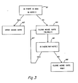
- FIG. 3 highlights the operation carried out by the circuit.
- FIG. 3 a series of boxes that represent certain decision points in carrying out the circuit operation.
- box 61 that is a decision as to whether there is high frequency content in the note. If the decision is yes then box 62 indicates that the noise gate is to be opened. This means that this signal goes thru without being rolled off as to high frequency content. If the decision from box 60 is a "no" then the noise gate is closed as illustrated by box 64.
- Box 66 couples from box 64 and indicates the question as to whether there is any note present.
- the determination as to whether there is high frequency content in the note is made by circuit 50.
- the decision as to whether there is a note or not is determined by circuit 60. If it is determined that there is a note then the indication by the way of lines 65 indicates that the closing of the noise gate continues on a slow release time basis. On the other hand if the decision from box 66 is "no" indicating that there is no note being sustained by the player then the noise gate is closed rapidly as indicated by the box 68 in FIG. 3.
Landscapes
- Engineering & Computer Science (AREA)
- Computer Networks & Wireless Communication (AREA)
- Signal Processing (AREA)
- Tone Control, Compression And Expansion, Limiting Amplitude (AREA)
Applications Claiming Priority (1)
| Application Number | Priority Date | Filing Date | Title |
|---|---|---|---|
| US06/877,225 US4809337A (en) | 1986-06-20 | 1986-06-20 | Audio noise gate |
Publications (1)
| Publication Number | Publication Date |
|---|---|
| EP0374326A1 true EP0374326A1 (de) | 1990-06-27 |
Family
ID=25369507
Family Applications (1)
| Application Number | Title | Priority Date | Filing Date |
|---|---|---|---|
| EP88312266A Withdrawn EP0374326A1 (de) | 1986-06-20 | 1988-12-22 | Audio-Rauschsperre |
Country Status (2)
| Country | Link |
|---|---|
| US (1) | US4809337A (de) |
| EP (1) | EP0374326A1 (de) |
Cited By (1)
| Publication number | Priority date | Publication date | Assignee | Title |
|---|---|---|---|---|
| EP0495672A3 (en) * | 1991-01-18 | 1992-12-23 | Nec Corporation | White noise suppression circuit |
Families Citing this family (16)
| Publication number | Priority date | Publication date | Assignee | Title |
|---|---|---|---|---|
| US5263091A (en) * | 1992-03-10 | 1993-11-16 | Waller Jr James K | Intelligent automatic threshold circuit |
| US5297213A (en) * | 1992-04-06 | 1994-03-22 | Holden Thomas W | System and method for reducing noise |
| US6154548A (en) * | 1997-09-27 | 2000-11-28 | Ati Technologies | Audio mute control signal generating circuit |
| US6311155B1 (en) | 2000-02-04 | 2001-10-30 | Hearing Enhancement Company Llc | Use of voice-to-remaining audio (VRA) in consumer applications |
| DE69942784D1 (de) * | 1998-04-14 | 2010-10-28 | Hearing Enhancement Co Llc | Verfahren und Vorrichtung, die es einem End-Benutzer ermöglichen, Hörer-Präferenzen für Hörbehinderte und Nicht-Hörbehinderte einzustellen |
| US7415120B1 (en) | 1998-04-14 | 2008-08-19 | Akiba Electronics Institute Llc | User adjustable volume control that accommodates hearing |
| US6442278B1 (en) | 1999-06-15 | 2002-08-27 | Hearing Enhancement Company, Llc | Voice-to-remaining audio (VRA) interactive center channel downmix |
| AR024353A1 (es) | 1999-06-15 | 2002-10-02 | He Chunhong | Audifono y equipo auxiliar interactivo con relacion de voz a audio remanente |
| US7266501B2 (en) | 2000-03-02 | 2007-09-04 | Akiba Electronics Institute Llc | Method and apparatus for accommodating primary content audio and secondary content remaining audio capability in the digital audio production process |
| US6351733B1 (en) | 2000-03-02 | 2002-02-26 | Hearing Enhancement Company, Llc | Method and apparatus for accommodating primary content audio and secondary content remaining audio capability in the digital audio production process |
| US20040096065A1 (en) * | 2000-05-26 | 2004-05-20 | Vaudrey Michael A. | Voice-to-remaining audio (VRA) interactive center channel downmix |
| US8121300B1 (en) | 2009-10-08 | 2012-02-21 | Loduca Joseph A | Drum accessory for gating of a microphone on a drum |
| US10096309B2 (en) | 2015-01-05 | 2018-10-09 | Rare Earth Dynamics, Inc. | Magnetically secured instrument trigger |
| WO2016112038A1 (en) | 2015-01-05 | 2016-07-14 | Suitor Stephen | Magnetically secured instrument trigger |
| US9875732B2 (en) | 2015-01-05 | 2018-01-23 | Stephen Suitor | Handheld electronic musical percussion instrument |
| US11335310B2 (en) | 2018-06-18 | 2022-05-17 | Rare Earth Dynamics, Inc. | Instrument trigger and instrument trigger mounting systems and methods |
Citations (3)
| Publication number | Priority date | Publication date | Assignee | Title |
|---|---|---|---|---|
| US3678416A (en) * | 1971-07-26 | 1972-07-18 | Richard S Burwen | Dynamic noise filter having means for varying cutoff point |
| US3921077A (en) * | 1973-06-06 | 1975-11-18 | Sanyo Electric Co | Noise reduction apparatus |
| US4322641A (en) * | 1979-12-11 | 1982-03-30 | Packburn Electronics | Noise reduction system |
Family Cites Families (7)
| Publication number | Priority date | Publication date | Assignee | Title |
|---|---|---|---|---|
| US3989897A (en) * | 1974-10-25 | 1976-11-02 | Carver R W | Method and apparatus for reducing noise content in audio signals |
| CA1214112A (en) * | 1983-10-12 | 1986-11-18 | William A. Cole | Noise reduction system |
| AT379274B (de) * | 1983-12-22 | 1985-12-10 | Akg Akustische Kino Geraete | Anordnung zur unterdrueckung der amplitudenspitzen am beginn von explosivlauten in einem elektroakustischen uebertragungssystem, an dessen eingang ein mikrophon angeordnet ist |
| GB8403509D0 (en) * | 1984-02-10 | 1984-03-14 | Barnett P W | Acoustic systems |
| US4703507A (en) * | 1984-04-05 | 1987-10-27 | Holden Thomas W | Noise reduction system |
| US4633501A (en) * | 1985-04-15 | 1986-12-30 | Werrbach Donn R | Program dependent crossover filter (PDC) |
| US4739514A (en) * | 1986-12-22 | 1988-04-19 | Bose Corporation | Automatic dynamic equalizing |
-
1986
- 1986-06-20 US US06/877,225 patent/US4809337A/en not_active Expired - Fee Related
-
1988
- 1988-12-22 EP EP88312266A patent/EP0374326A1/de not_active Withdrawn
Patent Citations (3)
| Publication number | Priority date | Publication date | Assignee | Title |
|---|---|---|---|---|
| US3678416A (en) * | 1971-07-26 | 1972-07-18 | Richard S Burwen | Dynamic noise filter having means for varying cutoff point |
| US3921077A (en) * | 1973-06-06 | 1975-11-18 | Sanyo Electric Co | Noise reduction apparatus |
| US4322641A (en) * | 1979-12-11 | 1982-03-30 | Packburn Electronics | Noise reduction system |
Non-Patent Citations (1)
| Title |
|---|
| RADIO FERNSEHEN ELEKTRONIK, vol. 27, no. 11, November 1978, pages 725-726, Berlin, DE; R. RADANDT: "Dynamisches Rauschfilter" * |
Cited By (2)
| Publication number | Priority date | Publication date | Assignee | Title |
|---|---|---|---|---|
| EP0495672A3 (en) * | 1991-01-18 | 1992-12-23 | Nec Corporation | White noise suppression circuit |
| AU647232B2 (en) * | 1991-01-18 | 1994-03-17 | Nec Corporation | Circuit for suppressing white noise in received voice |
Also Published As
| Publication number | Publication date |
|---|---|
| US4809337A (en) | 1989-02-28 |
Similar Documents
| Publication | Publication Date | Title |
|---|---|---|
| EP0374326A1 (de) | Audio-Rauschsperre | |
| US4322641A (en) | Noise reduction system | |
| US3989897A (en) | Method and apparatus for reducing noise content in audio signals | |
| US4357488A (en) | Voice discriminating system | |
| US4622692A (en) | Noise reduction system | |
| US20170103744A1 (en) | Multi-Channel Noise Reduction System with Direct Instrument Tracking | |
| WO2020171602A1 (ko) | 적응적 햅틱 신호 발생 장치 및 방법 | |
| WO2002021687A2 (en) | System and method for varying levels of low audio frequences inversely with audio signal level | |
| US3182271A (en) | Tone control circuit for emphasizing low volume high and low frequency signals | |
| US4479239A (en) | Sound detecting device | |
| EP0495672B1 (de) | Schaltung zur Unterdrückung von weissem Rauschen | |
| US4881047A (en) | Automatic gain expansion system | |
| CA1305431C (en) | Audio noise gate | |
| JPH03139097A (ja) | マイクの収音方式 | |
| US20040101148A1 (en) | Electronic appliance audio filtering based on output device selection | |
| US20090257601A1 (en) | Acoustic speaker system with strong bass capability | |
| US7130433B1 (en) | Noise reduction apparatus and noise reduction method | |
| KR100367775B1 (ko) | 저입력신호대역폭압축기와증폭기제어회로 | |
| JPS5935081B2 (ja) | パルス状ノイズ抑制回路 | |
| JP2791234B2 (ja) | 音声信号処理装置 | |
| JP4186307B2 (ja) | ハウリング防止装置 | |
| JP2942034B2 (ja) | 音声処理装置 | |
| JPH04363995A (ja) | 音声処理装置 | |
| KR930015711A (ko) | 비디오 카메라의 마이크로폰 신호 회로 | |
| US20230386438A1 (en) | Audio signal management system |
Legal Events
| Date | Code | Title | Description |
|---|---|---|---|
| PUAI | Public reference made under article 153(3) epc to a published international application that has entered the european phase |
Free format text: ORIGINAL CODE: 0009012 |
|
| AK | Designated contracting states |
Kind code of ref document: A1 Designated state(s): BE DE FR GB IT NL SE |
|
| 17P | Request for examination filed |
Effective date: 19901220 |
|
| 17Q | First examination report despatched |
Effective date: 19930903 |
|
| GRAH | Despatch of communication of intention to grant a patent |
Free format text: ORIGINAL CODE: EPIDOS IGRA |
|
| STAA | Information on the status of an ep patent application or granted ep patent |
Free format text: STATUS: THE APPLICATION IS DEEMED TO BE WITHDRAWN |
|
| 18D | Application deemed to be withdrawn |
Effective date: 19960410 |