EP0374366A2 - Dispositif pour l'acheminement de documents dans une station d'impression et/ou de lecture - Google Patents
Dispositif pour l'acheminement de documents dans une station d'impression et/ou de lecture Download PDFInfo
- Publication number
- EP0374366A2 EP0374366A2 EP89115435A EP89115435A EP0374366A2 EP 0374366 A2 EP0374366 A2 EP 0374366A2 EP 89115435 A EP89115435 A EP 89115435A EP 89115435 A EP89115435 A EP 89115435A EP 0374366 A2 EP0374366 A2 EP 0374366A2
- Authority
- EP
- European Patent Office
- Prior art keywords
- document
- feed
- alignment
- transport
- printing
- Prior art date
- Legal status (The legal status is an assumption and is not a legal conclusion. Google has not performed a legal analysis and makes no representation as to the accuracy of the status listed.)
- Withdrawn
Links
Images



Classifications
-
- B—PERFORMING OPERATIONS; TRANSPORTING
- B65—CONVEYING; PACKING; STORING; HANDLING THIN OR FILAMENTARY MATERIAL
- B65H—HANDLING THIN OR FILAMENTARY MATERIAL, e.g. SHEETS, WEBS, CABLES
- B65H29/00—Delivering or advancing articles from machines; Advancing articles to or into piles
- B65H29/58—Article switches or diverters
-
- G—PHYSICS
- G07—CHECKING-DEVICES
- G07B—TICKET-ISSUING APPARATUS; FARE-REGISTERING APPARATUS; FRANKING APPARATUS
- G07B1/00—Machines for printing and issuing tickets
Definitions
- the invention relates to a device for feeding receipts into a printing and / or reading station, with feed rollers, belts or the like. Means of transport and with a stop for aligning the supplied document before it is introduced into the printing and / or reading station.
- Such devices are known in various forms and applications.
- a common application is, for example, a printing device for printing check forms, but there are comparable devices for printing other receipts such as tickets, etc.
- Pure readers are also known and when printing some receipts a check must still be carried out using a reading device so that there is both a printing station and a reading station.
- the invention has for its object to provide a device of the type mentioned, which is designed to be as space-saving as possible, but in which the individual documents can still be aligned uninfluenced by the feed transport means and in which such alignment both with horizontal and at a document feed from below is possible, in which the document is conveyed upward from a lower-lying memory and is even bent before reaching the stop, without there being any bending stress when aligning the document, which could jeopardize the alignment.
- the aforementioned device is characterized in that a switch or the like in the feed direction of the document before the alignment stop.
- a branch is provided in the guideway of the document for this document and that the means of transport for feeding the document after the past the rear edge of the document in the feed direction can be reversed at the branch and the document can be at least partially moved back in the opposite direction into the switch and its branch.
- each document receives one of the means of transport for its before it is aligned with the alignment stop Infeed independent position, so that the same alignment conditions always exist for each document.
- the alignment is advantageously independent of whether the document has been fed in, for example, in the horizontal direction or previously from below.
- the feed mechanism can be arranged in a very space-saving manner in this way, because the means of transport used for feeding need not be more than the document length in the feed direction from the alignment stop.
- An even more space-saving and small-sized device can be created by moving the alignment stop (s) out of the way of the document, e.g. can be lowered or raised and moved the first time the document is fed - past the switch - until the document is moved back again.
- the document can first be moved beyond the stop area by the means of transport that serve to feed it, because the alignment stops are initially lowered.
- the switch can also be arranged relatively close to these alignment stops, because the document is then moved back again and thereby inserted into the switch, so that its front edge in the feed direction can then be moved against the alignment stop again in the use position.
- the feed rollers or the like Means of transport for the document can also capture this in its position shifted into the switch at its area which still protrudes from the switch and can be used to feed the separated document out of the switch against the alignment stop. In this way, these feed rollers receive a double function, with several feed rollers or the like generally being on the feed path of the document. Can only give means of transport and only the feed rollers closest to the alignment stop this double function need. These feed rollers can have a lower speed for the actual alignment movement than for the feed.
- the alignment stop can be moved away again after the alignment before the further transport of the document into the printing and / or reading station, vzw. be lowerable.
- An embodiment and application of the invention of its own worthy of protection can consist in a device of the type mentioned above, which is arranged within an automatic dispenser for banknotes and / or receipts, where it is all the more important to have a space-saving arrangement.
- the corresponding embodiment of the invention can consist in that a storage container is provided for the untreated documents, on which separating rollers or the like.
- Attack means of transport that the feed rollers for the isolated document to the alignment stop and the switch are equipped with a rotational speed that is excessive compared to the feed movement of the document when printing and / or reading, and that sensors, vzw in the area of the feed path of the document.
- Electromagnetic brakes are provided, which slow the running document down to a lower speed.
- a displacement-speed sensor preferably a clock disk equipped with a plurality of light barriers
- the signals of the displacement-speed sensor can be fed, for example, to a microcomputer, which can use an appropriate program to precisely control the brakes, clutches and the like.
- the drive units for separating and aligning the documents so that despite the alignment reduced feed rate of the document, which can be issued as quickly as possible.
- the storage container for the receipts can be arranged below and / or next to the device and the receipts can be fed upwards and / or approximately horizontally and via deflection rollers and / or transport rollers or belts get the way to the alignment stop and the switch in front of it.
- the device as a built-in module can correspond in its external dimensions to that of a banknote module within an automatic dispenser and can fit within the bank automatic dispenser to the place for dispensing a type of banknote and its means of transport.
- the device can be integrated within already designed or existing dispensers for banknotes, so that the bank customer can call up not only cash but also pre-printed checks on the dispenser.
- the manufacturer of the automatic dispenser does not have to take any special precautions to fit the device for printing receipts, but only to provide an appropriately standardized space, as is also provided for a type of banknote. Also the respective transfer transport means from the rear modules to the output slot can be used in this way.
- Embodiments of the device with respect to the deflection and feed rollers before the alignment stop and its coupling, as well as with respect to the drive motors used and also the switch, are the subject of claims 9 to 14.
- a further embodiment of the invention of its own worthy of protection is the subject of claims 15 to 22 and relates to the printing station or the printing support there provided with an ink ribbon cassette, which can be exchanged in an advantageous manner according to the features of these claims, so that the ink ribbon can be replaced.
- the removal direction for the assembly consisting of platen and ribbon cassette is directed transversely to the advance of the receipts, so that this assembly can be removed from the side of the device without extensive measures for opening and accessing this assembly being required on the device itself. This assembly is just as easily insertable from the side into the printing station.
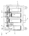
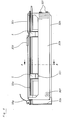
- a device designated as a whole with 1 is used for feeding receipts 2 into a printing station 3 and a reading station 4.
- both a printing station 3 and a reading station 4 are provided in the device 1, so that a printed receipt can be checked immediately .
- the device 1 described below could also be used if only one printing station 3 or one reading station 4 were present.
- a switch designated as a whole with 6 with a switch flap 7 is provided as a branch in the guideway of the document 2 for this document 2 and that Transport means to be described for feeding the document 2 can be reversed after the rear document edge in the feed direction has passed the branch, so that the document 2 can be at least partially moved back into the switch 6 and its branch in the opposite direction.
- the stop or stops 5 for alignment can be moved away from the path of the document 2, in the exemplary embodiment it can be lowered, but could also be movable laterally or upwards.
- the stop 5 can be removed from the document path until the document is moved back again, as a result of which - as already mentioned - it comes out of its original feed path out into the switch 6.
- feed rollers 8 with a corresponding counter roller 9 capture the document 2 and serve to feed the isolated document from the switch 6 against the alignment stop 5 which is then again in the use position.
- the document 2 is always aligned Position regardless of whether this document was fed from below, bent and thus deformed or fed horizontally and regardless of the feed speed and also the device 1 can be designed to be very space-saving because the feed rollers 8 and 9 are arranged close to the alignment stops 5 can, since the document for the alignment is first placed in a special position and only then aligned from it.
- the alignment stop 5 can be lowered again before the document 2 is transported further into the printing station 3 or the reading station 4, wherein the mechanism which also serves to move the stop 5 when the document 2 is first fed can be advantageously used .
- the device 1 could be used as an independent device in the smallest possible space and could be designed with its own housing as an independent device. 2, however, shows a particularly advantageous and expedient application and arrangement of the device 1 within an automatic dispenser for banknotes and payment documents, designated as a whole by 10. At least one storage container 11 for the untreated receipts 2 is provided within this automatic dispenser 10, on which separating rolls, belts 12 or the like. Attack means of transport.
- the feed rollers 8, 13 and 14, which transport the separated document 2 to the alignment stop 5, are one with respect to the front thrust movement of the document 2 when aligning, printing and / or reading excessive rotational speed equipped to be adapted to corresponding rotational speeds for the separation and output of banknotes 15 and their drive units.
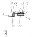
- 2 sensors are provided in the area of the feed path of the document, in the exemplary embodiment according to FIG. 3 fork light barriers 16, and on the feed rollers 8 near the aligning stop 5, in the exemplary embodiment an electromagnetic brake 17, whereby the incoming document 2 brakes to a lower speed can be.
- a displacement-speed sensor in this case a clock disk 18 equipped with a plurality of light barriers, is provided for measuring the speed of the incoming document 2 that is braked later.
- the storage container 11 for the receipts 2 can be arranged below, instead of or in addition to the device 1, as shown in dashed lines, and the receipts can be fed in from the bottom up and / or approximately horizontally and via deflection rollers 8 and / or transport rollers or belts on the way to the alignment stop 5 and the switch 6 located in front of it.
- the overall dimensions of this storage container 11 as a built-in module correspond to those of a banknote module 19 within the dispenser 10 and within the banknote dispenser 10 practically to the place for such a dispensing module 19 of a type of banknote and their means of transport fit.
- the dispenser 10 therefore practically does not need to be redesigned.
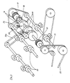
- a storage container 11 for receipts 2 with corresponding feed transport means can also be provided in addition to the device 1, as indicated by the broken line in FIG. 2, a main drive motor 27 is provided in the machine 10, which also causes the toothed belt wheel 23 and thus the separation and feeding of the documents 2 into the printing / reading device via a plurality of toothed belts.
- the deflection rollers or feed rollers 8 in front of the alignment stop 5 can be uncoupled from their main drive 27 and the clutch 21 can be controlled by the sensor 16.
- the signals of the displacement speed sensor 18, the light barrier 16 or the like. Measuring devices can be fed to a microcomputer, not shown, which can control clutch 21, brake 17, reversing the direction of rotation of the feed rollers and the like.
- a stepping motor 20 is connected for the further transport of the document 2 to the alignment stop 5, from there into the switch 6 and again to the alignment stop 5 via belt drives with the transport rollers 8 and takes over the transport of the document 2 when its front edge has passed the light barrier 16 , The transport rollers 8 are separated from the main drive 27 and braked to a lower speed.
- a further transport device for example in the form of transport rollers 22, can then be provided behind the printing and reading station, by means of which the documents 2 can be transported to an output station 28.
- the switch 6 is a branch from the transport direction of a document 2 directed against the usual feed direction and is designed as a guideway curved upwards from the horizontal. This allows the switch 6 and the receiving space formed by it for a document 2 to be aligned can be arranged within the outline of the entire device 1, in which the feed path also comes to lie from below. Thus, the switch and this alternative space for the document 2 to be separated does not influence the outer dimension of the device 1 in the lateral direction.
- a toothed belt wheel 23 belonging to the belt drive only drives the feed or deflection rollers 8 and thus also the document 2 when the electromagnetic clutch 21 is energized, that is to say when it is coupled.
- the operation of the device 1 is as follows:
- the main drive motor 27 is connected to the separating and feeding transport means for the receipts 2 from the storage container 11 via a belt 25 and corresponding transmissions. Above all, the belt 25 drives the toothed belt wheel 23, whereby further drives are actuated according to FIG.
- the running-in or take-over speed of the document 2 arriving from below or in the horizontal direction is reduced to such an extent that the document can be aligned exactly. Only then can the positionally accurate printing and / or reading on the document 2 take place.
- the document 2 arriving from below or horizontally is recognized by the light barriers 16, and the deflection rollers 8 connected to the main drive via the magnetic coupling 21 are disengaged.
- the electromagnetic brake 17 brakes the rollers 8 or the incoming document 2 to a lower speed.
- the speed of the incoming and later braked document is measured via the travel speed sensor and its clock disc 18.
- the clock disk 18 is slotted in a manner known per se and equipped with one or more light barriers.
- the signals of this displacement-speed sensor 18, as well as those of the light barrier 16, are fed to the microcomputer (not shown in any more detail) which controls the clutch 21, the brake 17, etc. via a corresponding program.
- the end coupling of the rollers 8 from the main drive and the braking by the magnetic brake 17 can be precisely controlled, especially via the sensor 18 in connection with the light barriers 16.
- the further transport of the document 2 is carried out by the stepper motor 20 via a belt 26 (Fig.3) and 26a.
- the document 2 to be processed is so far in the document running direction or conveyed on until its rear edge has completely passed the switch 6.
- the alignment stops 6 are completely removed or lowered from the path of the document 2, so that the document 2 can advance freely, for example, up to the transport rollers 22 (FIG. 1).
- the direction of rotation of the stepping motor 20 is reversed and the document 2 is thus transported backwards.
- the rear edge of the document 2 is deflected upwards in the direction of a shaft for a return of receipts.
- the distances of the stops 5 from the deflection roller 8 and the end of the switch 6 are shorter in a space-saving manner than the dimension of the document 2 in its feed direction.
- the document 2 is moved backwards until its front edge or its front edge is again in front of the alignment stops 5.
- these stops 5 are brought into the transport path of the document 2, that is to say placed upwards in the exemplary embodiment. Now the document running direction is changed again, that is, switched back to the original "forward" direction.
- the document 2 then moves under the action of the feed rollers 8 and in the alignment phase only under the action of the middle feed roller 8 and the alignment roller 9 which bears lightly on this against the stops 5 or 5 these measures are precisely aligned with the stops so that the front document reference edge is at 90 ° to the main axis, that is to say the direction of transport.
- the alignment stops 5 are lowered again and the document 2 is transported by the stepper motor 20 into the first print line position. Now the first print line is printed, the print head of the printing station 3 being transverse to the document transport direction Document is kept. Further lines can then be printed or the document can be conveyed further into the reading station 4.
- the read head can be arranged on the same carriage as the print head, that is, it can be guided over the document in the same way.
- the document 2 is conveyed further in the direction of the output of the automatic dispenser 10, the document being accelerated again to the speed of the main drive when it is taken over by a neighboring module. Accordingly, the transport rollers 22 have a freewheel in order to allow them to have a higher speed than them.
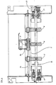
- the printing station 3 has an interchangeable, designed as a slide-in module, designated as a whole by 32, which has a platen 32a for a printhead 34 of the device 1 and an in a ribbon cassette 32b arranged, over the platen 32a leading ribbon 32 c contains.
- This assembly 32 consisting of platen 32a and ribbon cassette 32b or its holder to be described below, can be inserted and releasably fixed, in particular locked, below the print head transversely to the document feed indicated by arrow Pf 1 in FIG. 1 into a recess in the printing station 3.
- the ink ribbon cassette 32b is a so-called rod cassette, which is arranged in a stationary manner with respect to the print head during printing. It contains an endless ink ribbon 32c, which is placed in its interior in a plurality of loops, as is indicated by dashed lines in FIG. 9 and for which the term "stuffing cassette" is common. At both ends it has extensions for the entry and exit of the ink ribbon 32c, the distance between the extensions for the ink ribbon 32c running freely therebetween corresponding at least to the maximum printing width and the space required for the print head 34.
- the assembly 32 is in its in the printer frame with its side parts 29 u. 30 inserted position locked by means of a clamping lever 32g acting on the front end face in the removal direction against the removal direction of the assembly 32.
- Fig. 7 it can be seen that the thrust bearing 32a has on its longitudinal sides in the direction of insertion guides, in the embodiment grooves 38 (see Fig. 10), to which counter guides, in the embodiment, the guide plates 36 and 37 for the document 2 and fit behind the printing station 3, and that these guides and counter-guides interlock when inserted and in the use position.
- Fig. 7 illustrates how the guide plates 36 and 37 engage with their respective slightly bent down edges in the grooves 38.
- a wall piece or flange 32h is arranged on the underside of the beam-shaped platen 32a, which is arranged outside the vertical longitudinal center plane of the pressure beam 32a in a parallel plane to the longitudinal center plane and as a lateral stop and holder for those preferably interchangeably attached to it , eg lockable ribbon cassette 32 b is used.
- the alignment stops 5 already mentioned are also mounted on the assembly 32 according to FIGS. 6 to 10 and, in the exemplary embodiment, in vertical guide cutouts 32i of the pressure beam 32a on its first narrow side in the direction of advance of the document. If the alignment stops 5 stand up, as shown in FIG. 7, a document 2 cannot get into the printing station 3. The document can only be printed after the alignment edge 5 has been lowered. In the exemplary embodiment, these alignment stops 5 have, below the pressure beam 32a, downward-directed drive extensions 5a running on the opposite side, on which corresponding lifting and lowering devices for these stops 5 can engage when the module 32 is pushed in.
- the required ribbon cassettes are inserted into the device in the same direction in which the paper to be printed is fed or inserted, and removed again after use.
- the same direction as the paper means that the ribbon or the ribbon cassette is used approximately in the same width range as the paper or parallel to it, which presupposes that the printer must be accessible to the operator at least in its entire printing width when changing the cassette.
- this object is achieved in that the ribbon cassette 32b together with the platen 32a forms the exchangeable assembly 32 which can be inserted laterally into the printing station 3 and connected or locked to the printer frame.
- the assembly designated as a whole by 32, is designed as an insert and consists essentially of the platen 32a and the ribbon cassette 32b. 6 is in the operating position and is locked by means of the tensioning lever 33 mounted on the frame, which is located on the side part 29.
- a tab 32g serves as a movable connecting piece. The document 2 runs between the platen 32a and the freely stretched ink ribbon 32c and in this Representation of Figure 6 practically in the plane of the drawing.
- the print head 34 for example a matrix needle print head, is attached to the print carriage 35 and runs during printing - guided by the guide axis 31 - over the document 2. Threaded on the ink ribbon 32 c and attached to the print carriage 35 is an ink ribbon guide part 32 d. In this illustration, the printing carriage 35 is still outside the printing area and the document 2.
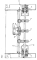
- FIG. 7 shows a cross section corresponding approximately to FIG. 1, also through the printing station 3.
- These sheets 36 and 37 are designed such that on the one hand they partially take over the guidance of the receipts 2 and on the other hand ensure that the slide-in module 32 is guided securely and held in a defined operating position relative to the print head 34 becomes.
- the document stops 5 are drawn in a raised position in FIG. 7, in which the document 2 is stopped and aligned in front of the printing station 3.
- the insert module 32 is partially pulled out of the printing station 3 to the side or only partially inserted.
- the clamping lever 33 is in the open, folded position.
- the tab 32 e is released and uncoupled from the tensioning lever 33 and its hook opening, into which this tensioning lever can be hooked in the closed position shown in FIG.
- the assembly 32 completely removed from the printing station 3 is shown in the view in FIG.
- the handle 32 e is located on the left, to which the tensile forces can be applied when the assembly 32 is removed, while on the opposite side detents 32 f can be seen which hold the cassette 32 b on its flat side.
- the ribbon guide part 32 d is threaded onto the freely stretched ink ribbon 32 c.
- the line A - B in FIG. 9 shows FIG. 10. It is clear that the wall or flange 32 h is firmly connected to the pressure beam 32 a.
- the ribbon cassette 32 b is arranged exchangeably. The ribbon cassette is held in this position by the detents 32 f which can be seen in FIG.
- the ink ribbon 32 c is driven by the gear 32 f, which is driven by a matching gear stored within the printing station 3 when the assembly 32 is pushed into its working position.
- the ribbon cassette 32 b can be removed from the pressure bar 32 a or the flange 32 h by being lifted in the direction of the central axis of the gear 32 f from the flange 32 h or from the catch 32 f.
- the ribbon can be removed in an unusual manner transversely to the document feeder in that it is arranged on this correspondingly extractable assembly 32, which can be pulled and pushed through an opening in the frame side part 29.
- the actual ribbon cassette can then be changed outside the printer, because the actual ribbon carrier, namely the flange 32 h, which is located on the platen 32 a, can first be removed.
- the entire device can be very space-saving in the feed direction be built and still be ensured with the help of the switch 6 that the document is no longer under the bending stress of the deflection roller 8 during alignment.
Landscapes
- Engineering & Computer Science (AREA)
- Mechanical Engineering (AREA)
- Physics & Mathematics (AREA)
- General Physics & Mathematics (AREA)
- Registering Or Overturning Sheets (AREA)
Applications Claiming Priority (2)
| Application Number | Priority Date | Filing Date | Title |
|---|---|---|---|
| DE19883842583 DE3842583A1 (de) | 1988-12-17 | 1988-12-17 | Vorrichtung zum zufuehren von belegen in eine druck- und/oder lesestation |
| DE3842583 | 1988-12-17 |
Publications (2)
| Publication Number | Publication Date |
|---|---|
| EP0374366A2 true EP0374366A2 (fr) | 1990-06-27 |
| EP0374366A3 EP0374366A3 (fr) | 1991-01-02 |
Family
ID=6369439
Family Applications (1)
| Application Number | Title | Priority Date | Filing Date |
|---|---|---|---|
| EP19890115435 Withdrawn EP0374366A3 (fr) | 1988-12-17 | 1989-08-22 | Dispositif pour l'acheminement de documents dans une station d'impression et/ou de lecture |
Country Status (2)
| Country | Link |
|---|---|
| EP (1) | EP0374366A3 (fr) |
| DE (1) | DE3842583A1 (fr) |
Cited By (1)
| Publication number | Priority date | Publication date | Assignee | Title |
|---|---|---|---|---|
| DE102009032228A1 (de) * | 2009-07-08 | 2011-01-13 | Giesecke & Devrient Gmbh | Vorrichtung und Verfahren für die Annahme oder Ausgabe von Banknoten |
Families Citing this family (2)
| Publication number | Priority date | Publication date | Assignee | Title |
|---|---|---|---|---|
| DE4339264A1 (de) * | 1993-11-18 | 1995-05-24 | Marcus Ziegler | Lottospielgerät |
| DE29818913U1 (de) * | 1998-10-23 | 2000-01-13 | Bundesdruckerei GmbH, 10969 Berlin | Sicherheitsdruckgerät zur Beschriftung von Personaldokumenten |
Family Cites Families (12)
| Publication number | Priority date | Publication date | Assignee | Title |
|---|---|---|---|---|
| US3641931A (en) * | 1970-03-31 | 1972-02-15 | Ibm | Analyzing, orienting and printing means in ticket handling mechanism |
| DE2441339A1 (de) * | 1970-10-09 | 1975-03-06 | Carrus | Vorrichtung zum kontinuierlichen drucken |
| JPS5026600A (fr) * | 1973-07-05 | 1975-03-19 | ||
| US4040345A (en) * | 1976-04-12 | 1977-08-09 | Cubic-Western Data | Ticket advance and printer mechanism |
| US4171129A (en) * | 1977-06-24 | 1979-10-16 | Scan-Optics, Inc. | Document transport |
| JPS58132582A (ja) * | 1982-01-27 | 1983-08-06 | インタ−ナショナル ビジネス マシ−ンズ コ−ポレ−ション | プラテンを含むリボンカ−トリツジ |
| JPS58207194A (ja) * | 1982-05-28 | 1983-12-02 | 株式会社日本コインコ | 紙幣受入装置 |
| US4587532A (en) * | 1983-05-02 | 1986-05-06 | Canon Kabushiki Kaisha | Recording apparatus producing multiple copies simultaneously |
| US4579228A (en) * | 1983-10-31 | 1986-04-01 | Cubic Western Data | Ticket diverter module |
| GB2159100B (en) * | 1984-05-18 | 1988-10-26 | Unisys Corp | Passbook printer |
| FR2566941B1 (fr) * | 1984-06-29 | 1986-12-19 | Dassault Electronique | Dispositif de traitement de titres cartonnes, propre a la creation et/ou au controle du titre |
| JPH0782556B2 (ja) * | 1986-11-28 | 1995-09-06 | 株式会社テック | 券発行機 |
-
1988
- 1988-12-17 DE DE19883842583 patent/DE3842583A1/de not_active Withdrawn
-
1989
- 1989-08-22 EP EP19890115435 patent/EP0374366A3/fr not_active Withdrawn
Cited By (2)
| Publication number | Priority date | Publication date | Assignee | Title |
|---|---|---|---|---|
| DE102009032228A1 (de) * | 2009-07-08 | 2011-01-13 | Giesecke & Devrient Gmbh | Vorrichtung und Verfahren für die Annahme oder Ausgabe von Banknoten |
| US8544629B2 (en) | 2009-07-08 | 2013-10-01 | Giesecke & Devrient Gmbh | Device and method for receiving or dispensing bank notes |
Also Published As
| Publication number | Publication date |
|---|---|
| EP0374366A3 (fr) | 1991-01-02 |
| DE3842583A1 (de) | 1990-06-21 |
Similar Documents
| Publication | Publication Date | Title |
|---|---|---|
| DE69226884T2 (de) | Druckvorrichtung | |
| DE3736878C2 (fr) | ||
| DE69515581T2 (de) | Vorrichtung zur Bearbeitung von Dokumenten | |
| DE69922718T2 (de) | Schreibträgermechanismus, Druckgerät mit diesem Schreibträgermechanismus und Verfahren zur Steuerung des Druckgerätes | |
| DE3800638A1 (de) | Doppeldruck-drucker | |
| DE2618089A1 (de) | Vorrichtung zum einfuehren eines einzelnen blattfoermigen kopietraegers in die kopietraegertransportbahn eines kopiergeraetes | |
| DE2912656A1 (de) | Vorrichtung zum wahlweisen zufuehren von endlospapier und einzelblaettern in schreibwerken | |
| DE3430943A1 (de) | Papierzufuehrungskassette | |
| DE3516460A1 (de) | Einrichtung zur voruebergehenden speicherung von belegen | |
| DD139474A5 (de) | Bildbetrachtungsgeraet | |
| DE69715270T2 (de) | Banknotenbearbeitungsmaschine | |
| DE69204202T2 (de) | Vorrichtung zum Behandeln von Blättern. | |
| EP3838604B1 (fr) | Imprimante d'étiquettes | |
| DE2216944A1 (de) | Vorrichtung zum Zuführen eines Informationträgerstreifens in ein Gerät zum Erkennen von Schriftzeichen | |
| EP3838601B1 (fr) | Imprimante d'étiquettes | |
| DE69801685T2 (de) | Drucker | |
| DE69409687T2 (de) | Vorrichtung zum Stapeln von Bogen | |
| DE3007838C2 (de) | Vorrichtung für Druckeinrichtungen zur Ablage von blattförmigen Aufzeichnungsträgern | |
| DE2638605B2 (de) | Farbband-Stopfkassette | |
| EP0374366A2 (fr) | Dispositif pour l'acheminement de documents dans une station d'impression et/ou de lecture | |
| DE3834061A1 (de) | Geldausgabegeraet mit gemeinsamem tansport von banknoten und beleg | |
| DE3514062A1 (de) | Wertscheingeber | |
| DE10203176A1 (de) | Vorrichtung zur Entgegennahme von gebündelten Scheinen wie Banknoten oder Scheckformularen | |
| EP1351871B1 (fr) | Dispositif d'emission destine a emettre des feuilles individuelles | |
| EP0159491B1 (fr) | Imprimante pour étiquettes |
Legal Events
| Date | Code | Title | Description |
|---|---|---|---|
| PUAI | Public reference made under article 153(3) epc to a published international application that has entered the european phase |
Free format text: ORIGINAL CODE: 0009012 |
|
| AK | Designated contracting states |
Kind code of ref document: A2 Designated state(s): CH DE ES FR GB IT LI SE |
|
| PUAL | Search report despatched |
Free format text: ORIGINAL CODE: 0009013 |
|
| AK | Designated contracting states |
Kind code of ref document: A3 Designated state(s): CH DE ES FR GB IT LI SE |
|
| STAA | Information on the status of an ep patent application or granted ep patent |
Free format text: STATUS: THE APPLICATION IS DEEMED TO BE WITHDRAWN |
|
| 18D | Application deemed to be withdrawn |
Effective date: 19910703 |