EP0374449A2 - Tragbares Fernsehgerät mit Zuordnung einer Teleskopantenne und eines Fernbedienungsgebers - Google Patents
Tragbares Fernsehgerät mit Zuordnung einer Teleskopantenne und eines Fernbedienungsgebers Download PDFInfo
- Publication number
- EP0374449A2 EP0374449A2 EP89120527A EP89120527A EP0374449A2 EP 0374449 A2 EP0374449 A2 EP 0374449A2 EP 89120527 A EP89120527 A EP 89120527A EP 89120527 A EP89120527 A EP 89120527A EP 0374449 A2 EP0374449 A2 EP 0374449A2
- Authority
- EP
- European Patent Office
- Prior art keywords
- remote control
- control transmitter
- recess
- portable television
- rear wall
- Prior art date
- Legal status (The legal status is an assumption and is not a legal conclusion. Google has not performed a legal analysis and makes no representation as to the accuracy of the status listed.)
- Granted
Links
- 230000001771 impaired effect Effects 0.000 description 1
Images
Classifications
-
- H—ELECTRICITY
- H04—ELECTRIC COMMUNICATION TECHNIQUE
- H04N—PICTORIAL COMMUNICATION, e.g. TELEVISION
- H04N5/00—Details of television systems
- H04N5/64—Constructional details of receivers, e.g. cabinets or dust covers
Definitions
- the invention relates to a portable television with assignment of a telescopic antenna and a remote control device, the front of the device being determined by the dimensions of the screen, and the back of the device housing, which is predominantly designed as a removable rear wall, rounded side surfaces and counter to the device. Front has tapered outer contours.
- Television sets are known in which a slot-shaped opening is provided on the front into which a remote control transmitter can be inserted when not in use.
- a storage location in the television set is thus assigned to the remote control transmitter.
- the opening slot is covered by a flap.
- Such a storage location for a remote control transmitter on the front of a television set is, however, complex and, in the case of television sets whose front side predominantly consists of the screen area, is not possible.
- the disadvantage is however, particularly in the case of portable television sets, if the remote control transmitter is not assigned a storage location in or on the television set.
- the object of the invention is therefore to find a simple storage option for a remote control transmitter assigned to the television set on the television set, the shape of the portable television set not to be impaired. Likewise, the placement of a telescopic antenna should not hinder the carrying of the device and the telescopic antenna pushed together should be protected on the device.
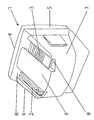
- the rear of a portable television set drawn in perspective can be seen with the assignment of a rod antenna 2 and a remote control transmitter 3.
- the rod antenna is in the example shown as a double telescopic antenna executed.
- the rod antenna can be pivoted and rotated via a joint.
- the dimensions of the device front, which is no longer visible, are almost entirely determined by the screen size.
- the back of the device which mainly consists of a rear wall 6 to be removed from the device housing 5, has rounded side surfaces 7 and tapering outer contours.
- a recess 8 is made on both sides in the outer area.
- a foldable and collapsible rod antenna 5 is inserted on one side and the remote control transmitter 3 required for the television set is inserted on the other side.
- the recess 8 in the rear wall 6 of the housing is designed such that the inserted remote control transmitter 3 forms a level closure with the top surface 9 of the rear wall 6. This also applies to the termination of the rod antenna 2 used, since it should also be excluded there that the rod antenna projects beyond the top surface 9 of the rear wall during a device transport.
- the rod antenna and the remote control transmitter are thus protected on the device for the transport of the device, or a specific storage location is assigned to the remote control transmitter.
- the recess 8 on the back of the device or in the rear wall of the device housing can also be designed such that an inserted remote control transmitter with the The rear wall is connected and can only be removed from the recess when it is moved slightly towards the front of the device.
- a fixation of the remote control transmitter in the recess 8 of the rear wall 6 can be carried out in a variety of ways. It is also conceivable that the two recesses are to be closed by means of a cover part both when the remote control transmitter is in place and when it is removed from the rear wall.
Landscapes
- Engineering & Computer Science (AREA)
- Multimedia (AREA)
- Signal Processing (AREA)
- Selective Calling Equipment (AREA)
- Transmitters (AREA)
- Support Of Aerials (AREA)
- Details Of Aerials (AREA)
- Details Of Television Systems (AREA)
Abstract
Description
- Die Erfindung betrifft ein tragbares Fernsehgerät mit Zuordnung einer Teleskopantenne und eines Fernbedienungsgerbers, wobei die Frontseite des Gerätes von den Abmessungen des Bildschirms bestimmt ist, und die Rückseite des Geräte-Gehäuses, die vorwiegend als abnehmbare Rückwand ausgebildet ist, abgerundete Seitenflächen und entgegen der Geräte-Frontseite verjüngende Außenkonturen aufweist.
- Es sind Fernsehgeräte bekannt, bei denen an der Frontseite eine schlitzförmige Öffnung vorgesehen ist, in die bei Nichtbenutzung ein Fernbedienungsgeber eingeschoben werden kann. Dem Fernbedienungsgeber ist somit eine Aufbewahrungsstelle im Fernsehgerät zugeordnet. Bei Herausnahme des Fernbedienungsgebers aus der Frontseite des Fernsehgerätes wird der Öffnungssschlitz mittels einer Verschlußklappe abgedeckt. Ein derartiger Aufbewahrungsort für einen Fernbedienungsgeber an der Frontseite eines Fernsehgerätes ist jedoch aufwendig und bei Fernsehgeräten deren Frontseite vorwiegend aus der Bildschirmfläche bestehen nicht möglich. Nachteilig ist jedoch insbesondere bei tragbaren Fernsehgeräten, wenn dem Fernbedienungsgeber keine Aufbewahrungsstelle im oder am Fernsehgerät zugeordnet ist.
- Aufgabe der Erfindung ist es daher, eine einfache Aufbewahrungsmöglichkeit für einen dem Fernsehgerät zugeordneten Fernbedienungsgeber am Fernsehgerät zu finden, wobei die Formgebung des tragbaren Fernsehgerätes nicht beeinträchtigt werden soll. Ebenso soll die Unterbringung einer Teleskopantenne das Tragen des Gerätes nicht behindern und die zusammengeschobene Teleskopantenne soll geschützt am Gerät untergebracht sein.
- Diese Aufgabe wird durch die kennzeichnenden Merkmale im Anspruch 1 gelöst.
- Die Unteransprüche zeigen vorteilhafte Ausgestaltungen der Erfindung.
- Die Erfindung wird nachfolgend anhand einer Zeichnung erläutert.
- In der vorliegenden Figur ist die Rückseite eines in perspektivischer Darstellung gezeichnetes tragbares Fernsehgerät mit Zuordnung einer Stabantenne 2 und eines Fernbedienungsgebers 3 zu erkennen. Die Stabantenne ist in dem dargestellten Beispiel als Doppel-Teleskopantenne ausgeführt. Über ein Gelenk ist die Stabantenne schwenk- und verdrehbar angeordnet. Die nicht weiter sichtbare Geräte-Frontseite ist in den Abmessungen nahezu ausschließlich von der Bildschirmgröße geprägt. Die Rückseite des Gerätes, die vorwiegend aus einer vom Geräte-Gehäuse 5 abzunehmenden Rückwand 6 besteht, weist abgerundete Seitenflächen 7 und allseits verjüngende Außenkonturen auf. In der Rückwand 6 des Geräte-Gehäuses ist beidseitig im Außenbereich je eine Vertiefung 8 eingebracht. In diese beiden Vertiefungen ist auf der einen Seite eine umklappbare und zusammenschiebbare Stabantenne 5 eingesetzt, und auf der anderen Seite ist der für das Fernsehgerät erforderliche Fernbedienungsgeber 3 eingelegt. Die Vertiefung 8 in der Rückwand 6 des Gehäuses ist derart ausgeführt, daß der eingelegte Fernbedienungsgeber 3 mit der Deckfläche 9 der Rückwand 6 einen höhengleichen Abschluß bildet. Dies trifft auch für den Abschluß der eingesetzten Stabantenne 2 zu, denn auch dort soll ausgeschlossen sein, daß die Stabantenne während eines Gerätetransportes über die Deckfläche 9 der Rückwand hinausragt. Somit ist für den Transport des Gerätes die Stabantenne und der Fernbedienungsgeber geschützt am Gerät untergebracht bzw. dem Fernbedienungsgeber ist ein bestimmter Aufbewahrungsort zugeordnet. Die Vertiefung 8 auf der Geräte-Rückseite bzw. in der Rückwand des Geräte- Gehäuses kann auch so ausgebildet sein, daß ein eingelegter Fernbedienungsgeber formschlüssig mit der Rückwand verbunden ist und erst bei leichtem Verschieben in Richtung zur Geräte-Frontseite aus der Vertiefung entnommen werden kann. Eine Fixierung des Fernbedienungsgebers in der Vertiefung 8 der Rückwand 6 kann jedoch auf die verschiedenste Art ausgeführt sein. Denkbar ist auch, daß die beiden Vertiefungen über ein Abdeckteil sowohl bei angelegtem als auch bei aus der Rückwand entnommenen Fernbedienungsgeber zu verschließen sind.
Claims (3)
Priority Applications (1)
| Application Number | Priority Date | Filing Date | Title |
|---|---|---|---|
| AT89120527T ATE101312T1 (de) | 1988-12-21 | 1989-11-06 | Tragbares fernsehgeraet mit zuordnung einer teleskopantenne und eines fernbedienungsgebers. |
Applications Claiming Priority (2)
| Application Number | Priority Date | Filing Date | Title |
|---|---|---|---|
| DE3842950 | 1988-12-21 | ||
| DE3842950A DE3842950A1 (de) | 1988-12-21 | 1988-12-21 | Tragbares fernsehgeraet mit zuordnung einer teleskopantenne und eines fernbedienungsgebers |
Publications (3)
| Publication Number | Publication Date |
|---|---|
| EP0374449A2 true EP0374449A2 (de) | 1990-06-27 |
| EP0374449A3 EP0374449A3 (de) | 1991-07-10 |
| EP0374449B1 EP0374449B1 (de) | 1994-02-02 |
Family
ID=6369674
Family Applications (1)
| Application Number | Title | Priority Date | Filing Date |
|---|---|---|---|
| EP89120527A Expired - Lifetime EP0374449B1 (de) | 1988-12-21 | 1989-11-06 | Tragbares Fernsehgerät mit Zuordnung einer Teleskopantenne und eines Fernbedienungsgebers |
Country Status (3)
| Country | Link |
|---|---|
| EP (1) | EP0374449B1 (de) |
| AT (1) | ATE101312T1 (de) |
| DE (2) | DE3842950A1 (de) |
Family Cites Families (1)
| Publication number | Priority date | Publication date | Assignee | Title |
|---|---|---|---|---|
| DE2901524C3 (de) * | 1979-01-16 | 1981-08-27 | Standard Elektrik Lorenz Ag, 7000 Stuttgart | Gerät der Unterhaltungselektronik mit einer in eine angepaßte Ausnehmung des Gerätegehäuses eingesetzten und daraus entnehmbaren Bedienungsvorrichtung |
-
1988
- 1988-12-21 DE DE3842950A patent/DE3842950A1/de not_active Withdrawn
-
1989
- 1989-11-06 EP EP89120527A patent/EP0374449B1/de not_active Expired - Lifetime
- 1989-11-06 AT AT89120527T patent/ATE101312T1/de not_active IP Right Cessation
- 1989-11-06 DE DE89120527T patent/DE58906900D1/de not_active Expired - Lifetime
Also Published As
| Publication number | Publication date |
|---|---|
| ATE101312T1 (de) | 1994-02-15 |
| DE58906900D1 (de) | 1994-03-17 |
| EP0374449B1 (de) | 1994-02-02 |
| DE3842950A1 (de) | 1990-06-28 |
| EP0374449A3 (de) | 1991-07-10 |
Similar Documents
| Publication | Publication Date | Title |
|---|---|---|
| DE2403116C3 (de) | Handkoffer mit an der Unterseite angeordneten Rollen und mit Deichsel | |
| DE3306629C2 (de) | Bügel für einen zusammenlegbaren Kopfhörer | |
| DE20218970U1 (de) | Gabelschlüssel | |
| DE8016012U1 (de) | Mundpflegegeraet in taschenformat | |
| DE3937516A1 (de) | Stehbildkameragehaeuse | |
| EP0809976A2 (de) | Folienschlauchabdeckung für medizinische Zwecke | |
| EP0374449B1 (de) | Tragbares Fernsehgerät mit Zuordnung einer Teleskopantenne und eines Fernbedienungsgebers | |
| DE4227064A1 (de) | Klapptisch | |
| DE3900165C2 (de) | ||
| DE8905589U1 (de) | Schutzhülle für Fernsteuerungen | |
| DE20001429U1 (de) | Einsatz zum Verankern einer Verbindungsschraube | |
| DE3311653C2 (de) | ||
| DE29823041U1 (de) | Zusammenlegbarer Werkzeugkasten | |
| DE2235451A1 (de) | Fahrbares ladegestell | |
| DE69905814T2 (de) | Verstellbare Eck-Verbindung für Kabelkanäle | |
| DE8209700U1 (de) | Verschlussvorrichtung fuer den gepaeckraum eines kraftfahrzeuges, insbesondere eines omnibusses | |
| DE9012274U1 (de) | Schließeinrichtung für den Wassereinfüllkanal von Dampfbügeleisen | |
| DE29922526U1 (de) | Vorrichtung zum Entwässern | |
| DE3300063C2 (de) | Diarahmen | |
| EP4567248A2 (de) | Bausatz für einen rahmen | |
| EP4501173A1 (de) | Vorrichtung zum parallelen ausschwenken einer plattform aus einem möbel sowie verbindungselement für eine solche vorrichtung | |
| DE102023207323A1 (de) | Vorrichtung zum parallelen Ausschwenken einer Plattform aus einem Möbel sowie Verbindungselement für eine solche Vorrichtung | |
| DE102023000759A1 (de) | Trittbrett für ein Fahrzeug sowie Fahrzeug mit demselben | |
| DE9109552U1 (de) | Verbindung von Ober- und Unterschale eines Handapparatekörpers | |
| DE2937794A1 (de) | Anordnung zum verbinden zweier geruestrohre in metallgeruesten |
Legal Events
| Date | Code | Title | Description |
|---|---|---|---|
| PUAI | Public reference made under article 153(3) epc to a published international application that has entered the european phase |
Free format text: ORIGINAL CODE: 0009012 |
|
| AK | Designated contracting states |
Kind code of ref document: A2 Designated state(s): AT DE FR IT |
|
| PUAL | Search report despatched |
Free format text: ORIGINAL CODE: 0009013 |
|
| AK | Designated contracting states |
Kind code of ref document: A3 Designated state(s): AT DE FR IT |
|
| 17P | Request for examination filed |
Effective date: 19911118 |
|
| 17Q | First examination report despatched |
Effective date: 19930716 |
|
| GRAA | (expected) grant |
Free format text: ORIGINAL CODE: 0009210 |
|
| AK | Designated contracting states |
Kind code of ref document: B1 Designated state(s): AT DE FR IT |
|
| REF | Corresponds to: |
Ref document number: 101312 Country of ref document: AT Date of ref document: 19940215 Kind code of ref document: T |
|
| REF | Corresponds to: |
Ref document number: 58906900 Country of ref document: DE Date of ref document: 19940317 |
|
| ET | Fr: translation filed | ||
| ITF | It: translation for a ep patent filed | ||
| PLBE | No opposition filed within time limit |
Free format text: ORIGINAL CODE: 0009261 |
|
| STAA | Information on the status of an ep patent application or granted ep patent |
Free format text: STATUS: NO OPPOSITION FILED WITHIN TIME LIMIT |
|
| 26N | No opposition filed | ||
| REG | Reference to a national code |
Ref country code: FR Ref legal event code: D6 |
|
| ITPR | It: changes in ownership of a european patent |
Owner name: OFFERTA LICENZA AL PUBBLICO OFFERTA LICENZA |
|
| REG | Reference to a national code |
Ref country code: FR Ref legal event code: CD |
|
| REG | Reference to a national code |
Ref country code: FR Ref legal event code: TP |
|
| REG | Reference to a national code |
Ref country code: FR Ref legal event code: TP |
|
| PGFP | Annual fee paid to national office [announced via postgrant information from national office to epo] |
Ref country code: DE Payment date: 20081210 Year of fee payment: 20 |
|
| PGFP | Annual fee paid to national office [announced via postgrant information from national office to epo] |
Ref country code: AT Payment date: 20081118 Year of fee payment: 20 |
|
| PGFP | Annual fee paid to national office [announced via postgrant information from national office to epo] |
Ref country code: IT Payment date: 20081120 Year of fee payment: 20 |
|
| PGFP | Annual fee paid to national office [announced via postgrant information from national office to epo] |
Ref country code: FR Payment date: 20081117 Year of fee payment: 20 |