EP0374465A1 - Anlage oder Vorrichtung mit Verwendung einer Universal-Richt- und Biegemaschine - Google Patents
Anlage oder Vorrichtung mit Verwendung einer Universal-Richt- und Biegemaschine Download PDFInfo
- Publication number
- EP0374465A1 EP0374465A1 EP89120950A EP89120950A EP0374465A1 EP 0374465 A1 EP0374465 A1 EP 0374465A1 EP 89120950 A EP89120950 A EP 89120950A EP 89120950 A EP89120950 A EP 89120950A EP 0374465 A1 EP0374465 A1 EP 0374465A1
- Authority
- EP
- European Patent Office
- Prior art keywords
- bending
- straightening
- working plane
- machine
- stock
- Prior art date
- Legal status (The legal status is an assumption and is not a legal conclusion. Google has not performed a legal analysis and makes no representation as to the accuracy of the status listed.)
- Withdrawn
Links
- 238000005452 bending Methods 0.000 title claims abstract description 73
- 239000000463 material Substances 0.000 claims abstract description 16
- 230000000750 progressive effect Effects 0.000 claims abstract description 3
- 239000010720 hydraulic oil Substances 0.000 claims description 2
- 238000007493 shaping process Methods 0.000 description 4
- 238000007599 discharging Methods 0.000 description 3
- 238000006073 displacement reaction Methods 0.000 description 2
- 238000004519 manufacturing process Methods 0.000 description 1
- 238000000034 method Methods 0.000 description 1
- 239000003921 oil Substances 0.000 description 1
- 230000002093 peripheral effect Effects 0.000 description 1
- 239000011150 reinforced concrete Substances 0.000 description 1
Images



Classifications
-
- B—PERFORMING OPERATIONS; TRANSPORTING
- B21—MECHANICAL METAL-WORKING WITHOUT ESSENTIALLY REMOVING MATERIAL; PUNCHING METAL
- B21D—WORKING OR PROCESSING OF SHEET METAL OR METAL TUBES, RODS OR PROFILES WITHOUT ESSENTIALLY REMOVING MATERIAL; PUNCHING METAL
- B21D11/00—Bending not restricted to forms of material mentioned in only one of groups B21D5/00, B21D7/00, B21D9/00; Bending not provided for in groups B21D5/00 - B21D9/00; Twisting
- B21D11/10—Bending specially adapted to produce specific articles, e.g. leaf springs
- B21D11/12—Bending specially adapted to produce specific articles, e.g. leaf springs the articles being reinforcements for concrete
-
- B—PERFORMING OPERATIONS; TRANSPORTING
- B21—MECHANICAL METAL-WORKING WITHOUT ESSENTIALLY REMOVING MATERIAL; PUNCHING METAL
- B21F—WORKING OR PROCESSING OF METAL WIRE
- B21F1/00—Bending wire other than coiling; Straightening wire
-
- B—PERFORMING OPERATIONS; TRANSPORTING
- B21—MECHANICAL METAL-WORKING WITHOUT ESSENTIALLY REMOVING MATERIAL; PUNCHING METAL
- B21F—WORKING OR PROCESSING OF METAL WIRE
- B21F1/00—Bending wire other than coiling; Straightening wire
- B21F1/006—Bending wire other than coiling; Straightening wire in 3D with means to rotate the tools about the wire axis
Definitions
- the present invention concerns a plant or apparatus utilizing a universal straightening-bending machine.
- This plant or machine finds particular if not exclusive application for straightening and bending of rods or metallic wire and hence for the realization of small or large stirrups, as well as for bending and shaping rods even of notable lengthiness and even to the respective opposed extremities.
- stirrup machines Other drawbacks of all this category of machines (known generally as stirrup machines, is that they have not the possibility of producing stirrups or shaped rods of great size for the evident impossibility to rotate great bulks and of notable lengthiness on a vertical or inclined plane.
- US-A-3052277 discloses a bending machine with pivotable work bending table about a horizontal axis to move the work table in any desired inclination also exceeding 90° relative to the horizontal plane.
- This machine solving a lot of problems concerning the possibility to utilize the best position for working as desired, being the rotary working table so realized not for solving one of the main scopes of this invention that is to facilitate the discharge of the realized stirrups.
- the scope of the present invention is to realize an universal apparatus able to make all the functions of the mentioned machines, obviating to the inconvenience to utilize different machines with different characteristics for each type of stirrup to be realized.
- a further scope of this invention is to make possible a better discharge of the stirrups produced utilizing the orientability of the working table as suggested by US-A-3052277 (STEGMANN) for different scope.
- a straightening-bending plant or apparatus utilizing a universal straightening-bending machine, associated with wire stock feeding means, in which the straightening-bending machine comprises in progressive order, on a pivotable working plane on hinging horizontal axis: - advancing and straightening means with opposed rolls to straighten and advance in longitudinal path said stock laying on said working plane, associated/able with eventual guiding means; - cutting means, laying on the same working plane, for cutting said stock material; - bending means for bending said stock material by means of central anvil means and bending nib, rotating around; characterized in that the respective working plane pivoting means are conceived to orient said working plane: - from a first approximately horizontal position, - to a second positive inclined position in which the working plane faces frontally and upwards; - to a third vertical position in which the the working plane faces frontally, - to a fourth negatively inclined position in which the the working plane faces frontally and downwards, and where
- the bending-straightening machine presents the bending group with able to bend in both clock-wise or counter-clockwise direction, in such a way it is possible, after and before the bending of head, make the rod to advance for the desired length, cutting it and bending it in other opposed extremity.
- a horizontal bench to support in lengthiness the advanced rods of differing length (meters) already bent to as first extremity can be associated, in order to allow further working to the opposite extremity to be cut and bent in further steps.
- the working plane in the corresponding position of the straightening station is narrowed allowing the operator to accompany manually large bent shaped forms.
- a second workbench with respective bending group can be associated to the first machine for bending the opposed extremity of an already worked rod is separated steps.
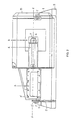
- the straightening-bending machine comprises a support structure (A) with lateral mullions (1) in which a working table (B) is pivotable on an horizontal axis (Y-Y), the rotation being realized by means of hydraulic cylinder (2-2′).
- plane (B) comprises: - a straightening group (3) placed in a tapered zone (3′) that let one clearance from the opposite side (S) for an operator when he has to work in horizontal condition; - advancing stock material (b) guide means (4) ; - a bending group (5) that includes cutting means (5′) and bending means (5 ⁇ ) the last ones comprising : - a central anvil (6) that can position itself over or under (by means of retraction, displacement under the rod and reissuing from the other side) the stock material to be bent, and - a peripheral bending nib (7) that can rotate both clockwise and anticlockwise and can retract itself and leaves passing from one side of the rod to the opposite side to allow clock-wise and anti-clockwise bending actions.
- the advancement path axis (X-X) of the row or stock material (b) is not coincident with the axis of rotation plan (Y-Y), but in working plane horizontally oriented and in working plane vertically oriented, it is higher then the pivoting axis X-X to allow: - the work with a horizontal plan (for big and large shapes) over any encumbrance means (C). - the work with the negative inclination (- ⁇ °) for free discharging the stirrups on a container (8), avoiding the bridling on the bending means. In this condition (figure 4) is even facilitated the realization of circular spiral-shaped stirrups by means of an orthogonal support axis (fig. 4′) further allowing easy discharging.
- auxiliary bending bench D
- b′ opposite bending in the same bar is carried out
- the machine utilizes hydraulic motors for all his operative groups.
- Fig. 1 is shown that the board of hydraulic command, with respective hydraulic oil reservoir is installed into the base, behind the working plane (C). This position is particularly advantageous for avoiding weights on the movable parts of the machine, and for maintaining the oil always in a straight position.
Landscapes
- Engineering & Computer Science (AREA)
- Mechanical Engineering (AREA)
- Bending Of Plates, Rods, And Pipes (AREA)
- Wire Processing (AREA)
Applications Claiming Priority (2)
| Application Number | Priority Date | Filing Date | Title |
|---|---|---|---|
| IT8353288 | 1988-11-23 | ||
| IT8883532A IT1226199B (it) | 1988-11-23 | 1988-11-23 | Impianto utilizzante una macchina piegatrice raddrizzatrice universale. |
Publications (1)
| Publication Number | Publication Date |
|---|---|
| EP0374465A1 true EP0374465A1 (de) | 1990-06-27 |
Family
ID=11322858
Family Applications (1)
| Application Number | Title | Priority Date | Filing Date |
|---|---|---|---|
| EP89120950A Withdrawn EP0374465A1 (de) | 1988-11-23 | 1989-11-11 | Anlage oder Vorrichtung mit Verwendung einer Universal-Richt- und Biegemaschine |
Country Status (6)
| Country | Link |
|---|---|
| US (1) | US5009097A (de) |
| EP (1) | EP0374465A1 (de) |
| JP (1) | JPH02224820A (de) |
| CA (1) | CA2002431A1 (de) |
| DK (1) | DK562389A (de) |
| IT (1) | IT1226199B (de) |
Cited By (8)
| Publication number | Priority date | Publication date | Assignee | Title |
|---|---|---|---|---|
| NL9401473A (nl) * | 1994-09-09 | 1996-04-01 | Holland Mechanics Bv | Buiginrichting. |
| FR2749199A1 (fr) * | 1996-06-03 | 1997-12-05 | Faure Bertrand Equipements Sa | Machine de cambrage de fils metalliques |
| GR1002854B (el) * | 1997-02-14 | 1998-02-06 | ������� �������� ������� ��� ��������� �����������.. | Μεθοδος και μηχανισμος παραγωγης σπιραλ απο συρμα ή μπετοβεργα ή μεταλλικο σωληνα τυχουσης διατομης με οχι μονο ταυτοσημο αλλα και διαφορετικο σχημα καθε ανελιξης |
| EP0875309A1 (de) * | 1997-04-29 | 1998-11-04 | M.E.P. Macchine Elettroniche Piegatrici S.p.A. | Bevorzugtes Biegesystem für Biegevorrichtungen |
| GR1003500B (el) * | 1999-04-06 | 2001-01-03 | ������� & ��� �� "������" | Ανακλινομενη μηχανη ευθυγραμμισεως, καμψεως και κοπης βεργων σιδηρου (αυτοματος ηλεκτρονικος τσερκαδορος) |
| WO2003024640A1 (en) * | 2001-09-14 | 2003-03-27 | M.E.P. Macchine Elettroniche Piegatrici Spa | Bending machine for profiles, such as reinforcement round pieces or similar |
| EP1331050A1 (de) * | 2002-01-24 | 2003-07-30 | M.E.P. Macchine Elettroniche Piegatrici S.p.A. | Ausstossvorrichtung für Profilstäbe oder Profilstabteile |
| LU103332B1 (de) * | 2024-07-15 | 2026-01-16 | Apilion Machines Services Gmbh | Biegevorrichtung und Biegeverfahren für Gitterträger |
Families Citing this family (4)
| Publication number | Priority date | Publication date | Assignee | Title |
|---|---|---|---|---|
| AT393640B (de) * | 1989-09-20 | 1991-11-25 | Evg Entwicklung Verwert Ges | Vorrichtung zum biegen von stabfoermigem material zu betonbewehrungselementen |
| US9375773B2 (en) | 2010-05-05 | 2016-06-28 | Textron Innovations Inc. | Circuit for conduit bender |
| CN103658452B (zh) * | 2013-12-12 | 2015-11-18 | 建科机械(天津)股份有限公司 | 钢筋自动弯箍机上的挡料机构 |
| EP3122485B1 (de) * | 2014-03-27 | 2018-01-31 | Massaro, Libero Angelo | Überschlagbare biegemaschine |
Citations (4)
| Publication number | Priority date | Publication date | Assignee | Title |
|---|---|---|---|---|
| US3052277A (en) * | 1958-07-17 | 1962-09-04 | Wirth Arno H Fa | Bending machine |
| FR1364770A (fr) * | 1963-05-17 | 1964-06-26 | Machine automatique pour couder des barres d'acier et façonner des épingles, étriers ou cadres | |
| DE2723846C2 (de) * | 1976-05-28 | 1982-08-19 | Rista-Drahtwerk Hufnagl & Co GmbH, Wien | Biegemaschine für Draht, insbesondere zur Herstellung von Betonarmierungseisen |
| AT368725B (de) * | 1981-01-30 | 1982-11-10 | Evg Entwicklung Verwert Ges | Kombinierte richt- und biegemaschine |
Family Cites Families (7)
| Publication number | Priority date | Publication date | Assignee | Title |
|---|---|---|---|---|
| NL293445A (de) * | ||||
| US1272552A (en) * | 1917-07-31 | 1918-07-16 | Robert P Spencer | Pipe-bending machine. |
| US3440859A (en) * | 1966-10-18 | 1969-04-29 | Xerox Corp | Corner forming apparatus |
| IT1024224B (it) * | 1974-11-15 | 1978-06-20 | Del Fabbro Remigio | Maochina staffarice ad alimen tazione continua oberante a recupero di materiale e relativo me todo di oberare per la qustruzio ne delle dette staffe |
| DE2918813A1 (de) * | 1979-05-10 | 1980-11-20 | Brueninghaus Gmbh Stahlwerke | Vorrichtung zum biegen von metallstaeben |
| US4485664A (en) * | 1982-09-20 | 1984-12-04 | J. A. Richards Company | Device for forming and bending metal |
| US4561279A (en) * | 1984-08-24 | 1985-12-31 | Leonard Wears | Rod bending and cutting apparatus |
-
1988
- 1988-11-23 IT IT8883532A patent/IT1226199B/it active
-
1989
- 1989-11-07 CA CA002002431A patent/CA2002431A1/en not_active Abandoned
- 1989-11-09 DK DK562389A patent/DK562389A/da not_active Application Discontinuation
- 1989-11-11 EP EP89120950A patent/EP0374465A1/de not_active Withdrawn
- 1989-11-17 US US07/438,771 patent/US5009097A/en not_active Expired - Fee Related
- 1989-11-22 JP JP1304551A patent/JPH02224820A/ja active Pending
Patent Citations (4)
| Publication number | Priority date | Publication date | Assignee | Title |
|---|---|---|---|---|
| US3052277A (en) * | 1958-07-17 | 1962-09-04 | Wirth Arno H Fa | Bending machine |
| FR1364770A (fr) * | 1963-05-17 | 1964-06-26 | Machine automatique pour couder des barres d'acier et façonner des épingles, étriers ou cadres | |
| DE2723846C2 (de) * | 1976-05-28 | 1982-08-19 | Rista-Drahtwerk Hufnagl & Co GmbH, Wien | Biegemaschine für Draht, insbesondere zur Herstellung von Betonarmierungseisen |
| AT368725B (de) * | 1981-01-30 | 1982-11-10 | Evg Entwicklung Verwert Ges | Kombinierte richt- und biegemaschine |
Cited By (12)
| Publication number | Priority date | Publication date | Assignee | Title |
|---|---|---|---|---|
| NL9401473A (nl) * | 1994-09-09 | 1996-04-01 | Holland Mechanics Bv | Buiginrichting. |
| FR2749199A1 (fr) * | 1996-06-03 | 1997-12-05 | Faure Bertrand Equipements Sa | Machine de cambrage de fils metalliques |
| GR1002854B (el) * | 1997-02-14 | 1998-02-06 | ������� �������� ������� ��� ��������� �����������.. | Μεθοδος και μηχανισμος παραγωγης σπιραλ απο συρμα ή μπετοβεργα ή μεταλλικο σωληνα τυχουσης διατομης με οχι μονο ταυτοσημο αλλα και διαφορετικο σχημα καθε ανελιξης |
| EP0864386A1 (de) * | 1997-02-14 | 1998-09-16 | Eurobend Sa | Methode und Vorrichtung zur Produktion von Spiralen aus Draht, Betonstahl oder einem metallischen Rohr |
| EP0875309A1 (de) * | 1997-04-29 | 1998-11-04 | M.E.P. Macchine Elettroniche Piegatrici S.p.A. | Bevorzugtes Biegesystem für Biegevorrichtungen |
| US5966979A (en) * | 1997-04-29 | 1999-10-19 | M.E.P. Macchine Elettroniche Piegatrici Spa | Bending machine and method having positionable drawing rolls and limiting mechanism defining a transit and containing space for the workpiece |
| GR1003500B (el) * | 1999-04-06 | 2001-01-03 | ������� & ��� �� "������" | Ανακλινομενη μηχανη ευθυγραμμισεως, καμψεως και κοπης βεργων σιδηρου (αυτοματος ηλεκτρονικος τσερκαδορος) |
| WO2003024640A1 (en) * | 2001-09-14 | 2003-03-27 | M.E.P. Macchine Elettroniche Piegatrici Spa | Bending machine for profiles, such as reinforcement round pieces or similar |
| US7004003B2 (en) | 2001-09-14 | 2006-02-28 | M.E.P. Macchine Elettroniche Piegatrici Spa | Bending machine for profiles |
| EP1331050A1 (de) * | 2002-01-24 | 2003-07-30 | M.E.P. Macchine Elettroniche Piegatrici S.p.A. | Ausstossvorrichtung für Profilstäbe oder Profilstabteile |
| LU103332B1 (de) * | 2024-07-15 | 2026-01-16 | Apilion Machines Services Gmbh | Biegevorrichtung und Biegeverfahren für Gitterträger |
| EP4681839A1 (de) * | 2024-07-15 | 2026-01-21 | apilion machines + services GmbH | Biegevorrichtung und biegeverfahren für gitterträger |
Also Published As
| Publication number | Publication date |
|---|---|
| IT1226199B (it) | 1990-12-21 |
| IT8883532A0 (it) | 1988-11-23 |
| CA2002431A1 (en) | 1990-05-23 |
| US5009097A (en) | 1991-04-23 |
| JPH02224820A (ja) | 1990-09-06 |
| DK562389A (da) | 1990-05-24 |
| DK562389D0 (da) | 1989-11-09 |
Similar Documents
| Publication | Publication Date | Title |
|---|---|---|
| CA2002431A1 (en) | Plant or apparatus utilizing a universal straightening-bending machine | |
| DE4010445C2 (de) | Rohrbiegemaschine | |
| DE2723846C2 (de) | Biegemaschine für Draht, insbesondere zur Herstellung von Betonarmierungseisen | |
| DE3327509A1 (de) | Biegevorrichtung | |
| EP3427372A1 (de) | Herstellungsverfahren für einen stator | |
| EP0194478B1 (de) | Vorrichtung zum Richten von Stäbe ohne eine um die Längsachse relative Verdrehung aufeinanderfolgender Materialsegmente | |
| CH671904A5 (de) | ||
| DE1627585C3 (de) | Rohrbiegemaschine | |
| DE1938225B2 (de) | Vorrichtung zum fraesen von woelbungen mit grossem radius | |
| CN2273868Y (zh) | 眼镜脚自动弯脚机 | |
| DE10214275A1 (de) | Biegemaschine für Profile und Rundrohre | |
| EP1579965B1 (de) | Vorrichtung zum stirnseitigen Bearbeiten eines eine Negativform für einen Gerinneast eines Schachtbodengerinnes bildenden Profilstückes | |
| DE102005047078B3 (de) | Biegemaschine, insbesondere Seilbiegemaschine | |
| EP2366470A2 (de) | Richtwalze, Richtwalzenanordnung und Zwei-Walzen-Richtmaschine sowie Richtverfahren | |
| DE2243293C2 (de) | Vorrichtung zum Biegen von strangförmigen Werkstücken | |
| DE19710046C2 (de) | Vorrichtung zum Biegen von Stahldraht zu Bügeln und Biegeformen | |
| EP1073533B1 (de) | Vorrichtung zur zuführung des anfangsendes eines drahtcoils zu einer ziehanlage | |
| AT404566B (de) | Richt- und schneidmaschine zur bearbeitung von betonstahl | |
| DE925404C (de) | Maschine zur Herstellung von aus wellenfoermig gebogenem Draht bestehenden Flachfedern | |
| CN215544480U (zh) | 六机头钢筋调直弯曲一体机 | |
| DE720880C (de) | Blechscher- und Vorbiegemaschine | |
| DE2918191A1 (de) | Verfahren und vorrichtung zur herstellung eines konvektorelements | |
| DE244162C (de) | ||
| US3526117A (en) | Bar forming machine | |
| DE392028C (de) | Einrichtung zur Fuehrung des Werkstuecks bei Schraegwalzenrichtmaschinen |
Legal Events
| Date | Code | Title | Description |
|---|---|---|---|
| PUAI | Public reference made under article 153(3) epc to a published international application that has entered the european phase |
Free format text: ORIGINAL CODE: 0009012 |
|
| AK | Designated contracting states |
Kind code of ref document: A1 Designated state(s): AT BE CH DE ES FR GB GR LI LU NL SE |
|
| 17P | Request for examination filed |
Effective date: 19900830 |
|
| STAA | Information on the status of an ep patent application or granted ep patent |
Free format text: STATUS: THE APPLICATION IS DEEMED TO BE WITHDRAWN |
|
| 18D | Application deemed to be withdrawn |
Effective date: 19920602 |