EP0374496A2 - Positionneurs pour les bords avant de feuilles - Google Patents
Positionneurs pour les bords avant de feuilles Download PDFInfo
- Publication number
- EP0374496A2 EP0374496A2 EP89121377A EP89121377A EP0374496A2 EP 0374496 A2 EP0374496 A2 EP 0374496A2 EP 89121377 A EP89121377 A EP 89121377A EP 89121377 A EP89121377 A EP 89121377A EP 0374496 A2 EP0374496 A2 EP 0374496A2
- Authority
- EP
- European Patent Office
- Prior art keywords
- bearing
- shaft
- cross member
- pivot
- joint
- Prior art date
- Legal status (The legal status is an assumption and is not a legal conclusion. Google has not performed a legal analysis and makes no representation as to the accuracy of the status listed.)
- Granted
Links
Images
Classifications
-
- B—PERFORMING OPERATIONS; TRANSPORTING
- B41—PRINTING; LINING MACHINES; TYPEWRITERS; STAMPS
- B41F—PRINTING MACHINES OR PRESSES
- B41F21/00—Devices for conveying sheets through printing apparatus or machines
- B41F21/12—Adjusting leading edges, e.g. front stops
-
- B—PERFORMING OPERATIONS; TRANSPORTING
- B65—CONVEYING; PACKING; STORING; HANDLING THIN OR FILAMENTARY MATERIAL
- B65H—HANDLING THIN OR FILAMENTARY MATERIAL, e.g. SHEETS, WEBS, CABLES
- B65H9/00—Registering, e.g. orientating, articles; Devices therefor
- B65H9/06—Movable stops or gauges, e.g. rising and falling front stops
Definitions
- the invention relates to a device for aligning leading edges of sheets to adjustable front marks of a feed device, in which the sheets are successively applied to the leading marks in a conveying direction perpendicular to the leading edges, and in which the leading marks are rotatably connected to a leading mark shaft, which in turn stored in a first and a second bearing of the application device and can be swiveled back and forth by means of a swiveling device about the longitudinal axis of the front mark shaft.
- One of the measures for registering sheets that are in register or in register is to align the leading edges of the sheets to be printed in a feed device preceding a printing unit. For this purpose, use is made in the prior art of adjustable front marks.
- Adjustable front marks are known for example from the document DE-C2-32 15 804.
- each of the front brands distributed over a front brand shaft is adjustable by means of an adjusting screw in and against the conveying direction relative to a front brand holder which is clamped to the front brand shaft.
- This also gives, inter alia, a possibility of adapting the front marks to a possibly curved course of the leading edges of the sheets and thus achieving a perfect contact of the front marks for aligning the sheets in the conveying direction.
- Such individual adjustment of each front brand is extremely tedious and time consuming.
- the front mark shaft is accommodated in eccentric bearings which are rotated accordingly in order to fix the stop of the sheets before the start of printing.
- this can only take into account a position of an otherwise straight front edge that possibly deviates from the perpendicular to the conveying direction.
- a device has become known from DE-A1 35 04 435, by means of which a sheet leading edge aligned on a feeder can be deformed by means of the feed drum after the transfer of a sheet to a feed drum.
- the feed drum is equipped with a register rail provided with stops, which can be deformed from a normally straight course into a curved course by means of adjusting screws.
- the straight front edge of the sheet is fed to the abovementioned stops at a speed which is above the peripheral speed of the feed drum, so that the front end of the sheet bulges at the stops and the leading edge of the sheet lies snugly against each of the stops and accordingly wraps around the feed drum with the bow deformed the curvature of the register rail.
- the present invention has for its object to design a device described above so that an adaptation of the front marks to a curved course of the Front edges of the sheet is possible without complex measures for adjusting the front marks.
- this object is achieved for a generic device by means of a bending device acting in a stationary manner on the front mark shaft for the selectable setting of a curve of the longitudinal axis of the front mark shaft which is curved in or against the conveying direction or a straight line.
- a device according to the invention can be used with particular advantage if sheet stacks are to be processed in a printing press, in which, depending on their history, the edges of the sheets intended for contact with the front marks are convexly or concavely curved.
- sheet stacks can also be processed in an advantageous manner, for example, in which curved edges have formed convexly due to storage in rooms that are too dry and concavely curved when stored in rooms that are too moist.
- FIG. 1 Facilities are known with which a swelling of freshly printed sheets is taken into account.
- Bending devices used here work periodically in time with a printing press and deform the leading edges of the sheets after grippers have been closed, by means of which the sheets are transported until they are transferred to subsequent grippers.
- the bending devices used for this purpose bring about joint deflections of gripper supports and associated gripper fingers or only deflections of gripper supports, in the latter case roughly designed gripper support surfaces causing displacements of the sheet relative to associated gripper fingers (US Pat. No. 4,466,350; DE-OS 20 52 786).
- Such devices are used to counter the so-called fanning out of the sheets when passing through a printing unit.
- Such bending devices are not suitable for devices for aligning leading edges of sheets on adjustable front marks, since the leading edges to be deformed by means of these bending devices must first be aligned with leading marks before they are deformed.
- the known bending devices effective at the front edges can only cause adjustments of gripper systems, which already aligned sheets are available. This is where the invention comes in and opens up the possibility of providing sheets with curved leading edges aligned for takeover by the gripper system without complex measures for adjusting the leading marks.
- the subject matter of the invention enables simultaneous adjustment of all Front marks on a curved course of leading edges on sheets to be processed.
- a particularly expedient embodiment of the subject of the invention is characterized in that the bending device has a third bearing, which is arranged substantially centrally between the first bearing and the second bearing and accommodates the front marker shaft, and which can be displaced into deflected positions with respect to a central position in which the front marker shaft is one has a straight longitudinal axis.
- a generic device with a first swivel part carrying the first bearing, which is connected to a support part by means of a first joint, and a second swivel part which supports the second bearing and which is connected to the support part by means of a second joint, a bearing lever carrying the third bearing, which is connected to the supporting part by means of a third joint, a horizontal geometric pivot axis which is common to the first, second and third joint and extends transversely to the conveying direction, pivot means for setting selectable pivot positions of the two pivot parts with respect to the common geometric pivot axis, a crossbar connected to the bearing lever, which is rotatably supported by means of a fourth bearing in each of the two pivoting parts, and such a design of the bearings and joints that the longitudinal axis of the front brand shaft opposite de r common geometric swivel axis oblique is adjustable, characterized in that the bending device is formed from the bearing lever articulated to the supporting part, the cross member mounted
- This embodiment is particularly advantageous insofar as it also allows all front marks to be adapted to curved leading edges with little effort, even if an obliquely adjustable front marker shaft is provided for adaptation to an additionally inclined leading edge.
- the design effort can also be kept small by the fact that the adjusting means are formed from spring-loaded clamping means, which strive to reduce the distance between the bearing lever and the crossmember, and from one opposing and opposing the clamping means the crossbar adjustable stop.
- the spring-loaded tensioning means are formed from the traverse cross-penetrating tie rods with an articulated connection to the bearing lever located on this side of the crossbar and between the third bearing and the third joint, one beyond the crossbar this protruding shaft of a respective tie rod and a compression spring clamped between a shoulder at the end of the shaft and the crossbar, and that the stop which is adjustable with respect to the crossbar is formed from a set screw which penetrates the crossbar and is screwed into the crossbar.
- the third bearing also reduces bending vibrations of the front mark shaft, which can be caused by the pivoting device acting on the front mark shaft. This advantage is given in a device according to the invention in particular in an embodiment which is characterized in that the pivoting device acts on the front mark shaft in the immediate vicinity of the third bearing.
- a further embodiment of a device according to the invention takes advantage of the favorable influence with regard to the reduction of torsional and bending vibrations, to which the front mark shaft can be excited by the pivoting device acting on it, which is characterized in that the bending device is used to support the Front marker shaft provided pair of spaced-apart third bearings, which are arranged symmetrically with respect to the first bearing and the second bearing and can be displaced by means of respective adjusting means in deflected positions with respect to a central position in which the front marker shaft has a straight longitudinal axis, and that the pivoting device is essentially centered between the first bearing and the second bearing on the front mark shaft.
- such a device proves to be user-friendly, which is characterized in that the respective adjusting means are connected to one another by means of a connecting element for common adjustment.
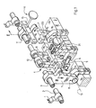
- the front marks 1 of a device according to the invention according to FIG. 1 are supplied with sheets for aligning their front edges one after the other in a conveying direction perpendicular to these front edges.
- the means required for this are not part of the subject matter of the invention and are therefore not shown and not explained in detail. Corresponding sheets are also not shown. To simplify the illustration, only two of the front marks 1, which are non-rotatably connected to the front mark shaft 2 and distributed over their length, are shown in FIG. 1.
- the front marker shaft 2 is rotatably received in a first bearing 3 and a second bearing 3 'and connected to a pivoting device 4 for pivoting the front marker shaft 2 about its longitudinal axis.
- the structural design of the swivel device 4 is not part of the subject matter of the invention and only here exemplified as a rotationally fixedly connected to the front marker shaft 2 rocker arm 5 with an articulated crank rod 6 of a crank mechanism, not shown in detail.
- the first bearing 3 is carried by a first pivot part 7 and the second bearing 3 'by a second pivot part 7'. Via a first joint 8 or a second joint 8 ', one of the two pivot parts 7 and 7' is connected to a stationary support part 9, the ends of which are fastened to side walls, also not shown.
- a third bearing 10 receiving the front marker shaft 2 is provided, and a bearing lever 11 bearing the third bearing 10 is connected to the support part 9 by means of a third joint 12.
- the first, second and third joint 8 and 8 'and 12 are each provided at a lower end of the two pivot parts 7 and 7' and the bearing lever 11 and arranged so that the first, second and third joint 8, 8 'and 12 have a common fixed geometric pivot axis 13 which runs horizontally, while the first and second bearings 3 and 3 'are each arranged at an upper end of the pivot parts 7 and 7' and the third bearing 10 at the upper end of the bearing lever 11 is.
- the geometric pivot axis 13 also extends transversely to the conveying direction.
- the front marker shaft 2 can thus perform a pivoting movement with respect to the geometric pivot axis 13 in and against the conveying direction.
- the pivoting device 4 provided for pivoting the front marker shaft 2 about its longitudinal axis acts on the front marker shaft 2 in the immediate vicinity of the third bearing 10.
- each of the two pivot parts 7 and 7 ' can be brought into a selectable pivot position.
- a further support member 15 is provided, which faces the upper ends of the pivot parts 7 and 7 '.
- the support member 15 is in turn attached at its ends to the side walls, not shown.
- Fig. 1 for the sake of simplicity, only a portion of the support member 15 opposite the right-hand pivot part 7 'in the drawing and the actuating means 14 acting on this pivot part are shown.
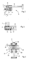
- FIG. 2 An example of the construction of the pivot means 14 is shown in detail in FIG. 2.
- the support member 15 reaching through clamping screw 16 is screwed into an upper end of a pivoting part 7 'and 7, respectively.
- a clamped under the screw head of the clamping screw 16 and supported against the supporting part 15 spring 17 presses the respective pivot part 7 'or 7 in the direction of the supporting part 15 against an adjustable stop which is formed by an adjusting spindle 18 mounted in the supporting part 15.
- a cross member 20 is rotatably mounted at its ends in one of the pivot parts 7 and 7 '.
- a constructive example of this storage is shown in Fig. 3.
- a fourth bearing 19 is used in the pivot parts 7 and 7 '.
- a bolt 21 is inserted, which is fitted in each end bore 22 of the cross member 20 and is secured in position relative to this by means of a locking screw 23.
- the first, second and third bearings 3 or 3 'or 10 and the first, second and third joint 8 or 8' or 12 are formed such that the longitudinal axis of the front mark shaft 2 is adjustable obliquely with respect to the common geometric pivot axis 13 by means of the pivot means 14.
- An inclination of the front marker shaft can be achieved by different adjustment paths of the two adjusting spindles 18.
- the cross member 20 is also inclined as a result of its mounting in the pivot parts 7 and 7 'and a pivoting of the bearing lever 11 connected to the cross member 20.
- the bending device acting on the front marker shaft 2 is now formed from the bearing lever 11 connected to the supporting part 9, the cross member 20 mounted in a respective pivot part 7 or 7 'and from adjusting means 24 which - as explained further below - on the one hand Connect the bearing lever 11 and the cross member 20 to one another and by means of which on the other hand a selectable distance 25 (FIG. 4) between the bearing lever 11 and the cross member 20 can be set.
- the possibility is now created to shift the third bearing 10 into deflected positions with respect to a central position in which the front marker shaft 2 has a linear longitudinal axis front marks 1 connected to the front mark shaft 2 can adapt to a curved course of a front edge of a sheet.
- a course of the longitudinal axis of the front marker shaft 2 that is curved or straight in the direction of the conveying direction or can be set. Given the curvature of the leading edge, the distance 25 matched thereto is maintained, so that the bending device acts stationary on the leading mark shaft 2.
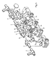
- actuating means 24, generally designated 24 in FIG. 1 and explained below, are shown more clearly.
- a part of these adjusting means which connects the crossbeam 20 and the bearing lever 11 to one another is formed from spring-loaded tensioning means which endeavor to reduce the distance 25.
- These tensioning means consist of tie rods 26, which penetrate the cross member 20 transversely and on this side of the cross member 20 between the third bearing 10 and the third joint 12 have an articulated connection to the bearing lever 11, and a beyond the cross member 20 from this outstanding shaft 27 of a respective one Tie rod 26, as well as from a compression spring 29 clamped between a shoulder 28 at the end of the respective shaft 27 and the cross member 20.
- For the articulated connection of the tie rods 26 with the bearing lever 11, these are screwed transversely into exposed ends of an articulated bolt 30, which in turn the Bearing lever 11 penetrates transversely.
- a part of the adjusting means 24 determining the distance 25 counteracts the spring-loaded tensioning means 26 to 30 and is formed from a stop adjustable in relation to the cross member 20 in the form of an adjusting screw 31 screwed into the cross member 20.
- all front marks can be adjusted simultaneously, even if the leading edges of the sheets are curved, by actuating a single adjusting member in the form of the set screw 31. Such a procedure is possible even if an inclination of the front marker shaft 2 is also required.
- a second embodiment shown in FIG. 5 differs from that of FIG. 1 in that instead of one single bearing lever 11 two bearing levers 11 are provided, each of which carries a third bearing 10 for mounting the front marker shaft 2.
- the spaced apart third bearing 10 are arranged symmetrically with respect to the first bearing 3 and the second bearing 3 '.
- the two bearing levers 11 are connected to the crossmember 20 in the same way as shown in FIGS. 1 and 4.
- the pivoting device 4 engages substantially centrally between the first bearing 3 and the second bearing 3 'on the front marker shaft 2.
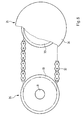
- the respective set screws 31 of the respective setting means 24 in the exemplary embodiment according to FIG. 5 can be connected to one another by means of a connecting member 32 for common adjustment.
- a connecting member 32 for common adjustment.
- a respective adjusting screw 31 is connected in a rotationally fixed manner to a chain wheel 33.
- the connecting link 32 is represented by a chain placed around these chain wheels 33.
- one of the adjusting means 24 - as shown on the left in FIG. 6 - can be provided with an adjusting screw 31 without a handwheel 34.
Landscapes
- Registering Or Overturning Sheets (AREA)
- Sheets, Magazines, And Separation Thereof (AREA)
Applications Claiming Priority (2)
| Application Number | Priority Date | Filing Date | Title |
|---|---|---|---|
| DE3843152 | 1988-12-22 | ||
| DE3843152A DE3843152A1 (de) | 1988-12-22 | 1988-12-22 | Einrichtung zum ausrichten von vorderkanten von bogen |
Publications (3)
| Publication Number | Publication Date |
|---|---|
| EP0374496A2 true EP0374496A2 (fr) | 1990-06-27 |
| EP0374496A3 EP0374496A3 (en) | 1990-07-25 |
| EP0374496B1 EP0374496B1 (fr) | 1993-06-16 |
Family
ID=6369789
Family Applications (1)
| Application Number | Title | Priority Date | Filing Date |
|---|---|---|---|
| EP89121377A Expired - Lifetime EP0374496B1 (fr) | 1988-12-22 | 1989-11-18 | Positionneurs pour les bords avant de feuilles |
Country Status (5)
| Country | Link |
|---|---|
| US (1) | US5033732A (fr) |
| EP (1) | EP0374496B1 (fr) |
| JP (1) | JP2610054B2 (fr) |
| CA (1) | CA2001920C (fr) |
| DE (3) | DE8817034U1 (fr) |
Cited By (1)
| Publication number | Priority date | Publication date | Assignee | Title |
|---|---|---|---|---|
| EP0614760A1 (fr) * | 1993-02-27 | 1994-09-14 | Heidelberger Druckmaschinen Aktiengesellschaft | Butée pour aligner le bord avant des feuilles sur une table de mange |
Families Citing this family (6)
| Publication number | Priority date | Publication date | Assignee | Title |
|---|---|---|---|---|
| DE4134767A1 (de) * | 1991-10-22 | 1993-04-29 | Heidelberger Druckmasch Ag | Vorrichtung zur vorderkantenausrichtung |
| DE4410529C2 (de) * | 1994-03-26 | 1998-07-02 | Heidelberger Druckmasch Ag | Vorrichtung zur Schrägbogenkorrektur im Anleger einer Bogendruckmaschine |
| DE19503739C1 (de) * | 1995-02-04 | 1996-04-04 | Heidelberger Druckmasch Ag | Vorrichtung zur Vermeidung von Passerfehlern |
| DE19546066C2 (de) * | 1995-12-09 | 1999-08-05 | Koenig & Bauer Ag | Einrichtung zum Ausrichten von Vordermarken |
| GB2363590A (en) * | 2000-05-18 | 2002-01-02 | James Burn Internat Ltd | A Punching Apparatus |
| JP5011171B2 (ja) * | 2007-03-09 | 2012-08-29 | リョービ株式会社 | 印刷機 |
Family Cites Families (9)
| Publication number | Priority date | Publication date | Assignee | Title |
|---|---|---|---|---|
| US3125022A (en) * | 1964-03-17 | Registering adjustment for multi-color printing | ||
| US2069918A (en) * | 1936-08-26 | 1937-02-09 | Willard Mfg Corp | Stop guide adjustment for printing presses |
| US2577099A (en) * | 1946-06-14 | 1951-12-04 | Hoe & Co R | Method of and means for registering impressions in multiunit sheet printing machines |
| US2976038A (en) * | 1957-06-17 | 1961-03-21 | Whyte Fred | Feed mechanisms for printing and like machines |
| DE1909795C2 (de) * | 1969-02-27 | 1973-10-18 | Heidelberger Druckmaschinen Ag, 6900 Heidelberg | Einrichtung an Bogenübergabetrommeln vonMehrfarben-Bogenrotationsdruckmaschinen zur Passerkorrektur durch Verformen der Bogenvorderkante |
| DE2052786A1 (de) * | 1970-10-28 | 1972-05-04 | North American Rockwell Corp , (n d Ges d Staates Delaware), Pitts burgh, Pa (V St A) | Blattzubnngervornchtung fur Druck maschinen |
| DE3112964A1 (de) * | 1981-04-01 | 1982-10-21 | Heidelberger Druckmaschinen Ag, 6900 Heidelberg | "bogenuebertragungszylinder von bogenrotationsdruckmaschinen mit einer einrichtung zur passerkorrektur der aufdrucke" |
| JPS57182443A (en) * | 1981-05-08 | 1982-11-10 | Komori Printing Mach Co Ltd | Front guide device for sheet fed press |
| DE3504435A1 (de) * | 1985-02-09 | 1986-08-14 | Miller-Johannisberg Druckmaschinen Gmbh, 6200 Wiesbaden | Bogen-druckmaschine mit bogenanlage an einem druckmaschinen-zylinder |
-
1988
- 1988-12-22 DE DE8817034U patent/DE8817034U1/de not_active Expired - Lifetime
- 1988-12-22 DE DE3843152A patent/DE3843152A1/de not_active Withdrawn
-
1989
- 1989-10-31 CA CA002001920A patent/CA2001920C/fr not_active Expired - Fee Related
- 1989-11-18 DE DE8989121377T patent/DE58904731D1/de not_active Expired - Fee Related
- 1989-11-18 EP EP89121377A patent/EP0374496B1/fr not_active Expired - Lifetime
- 1989-12-13 JP JP1321583A patent/JP2610054B2/ja not_active Expired - Lifetime
- 1989-12-22 US US07/455,303 patent/US5033732A/en not_active Expired - Lifetime
Cited By (2)
| Publication number | Priority date | Publication date | Assignee | Title |
|---|---|---|---|---|
| EP0614760A1 (fr) * | 1993-02-27 | 1994-09-14 | Heidelberger Druckmaschinen Aktiengesellschaft | Butée pour aligner le bord avant des feuilles sur une table de mange |
| US5496023A (en) * | 1993-02-27 | 1996-03-05 | Heidelberber Druckmaschinen Ag | Leading edge stop for aligning paper sheets on a feeder table |
Also Published As
| Publication number | Publication date |
|---|---|
| JPH02188345A (ja) | 1990-07-24 |
| CA2001920A1 (fr) | 1990-06-22 |
| DE8817034U1 (de) | 1992-04-30 |
| CA2001920C (fr) | 1994-11-15 |
| EP0374496A3 (en) | 1990-07-25 |
| DE3843152A1 (de) | 1990-06-28 |
| US5033732A (en) | 1991-07-23 |
| JP2610054B2 (ja) | 1997-05-14 |
| DE58904731D1 (de) | 1993-07-22 |
| EP0374496B1 (fr) | 1993-06-16 |
Similar Documents
| Publication | Publication Date | Title |
|---|---|---|
| DE3923362C2 (fr) | ||
| DE102004041472B4 (de) | Vorrichtung zum Transportieren eines Bedruckstoffbogens | |
| EP0570689B1 (fr) | Dispositif pour tendre un cliché d'impression sur le cylindre porte-plaque d'une machine à imprimer, particulièrement une machine à imprimer offset des feuilles | |
| EP0372237B1 (fr) | Dispositif de correction du repérage de la surimpression sur une feuille dans une rotative à feuilles | |
| DE3738674C2 (fr) | ||
| EP0374496B1 (fr) | Positionneurs pour les bords avant de feuilles | |
| DE9116367U1 (de) | Zylinder für die Papierführung an Bogenrotationsdruckmaschinen | |
| DE3538323A1 (de) | Einrichtung fuer das seitliche anlegen von flachen, zu einem fortlaufenden band geordneten gegenstaenden | |
| DE4230218C2 (de) | Vorgreifer einer Bogendruckmaschine | |
| DE4239254C2 (de) | Einrichtung zum Einstellen der Anlegmarken | |
| DE3429008C2 (de) | Vorrichtung zum Transportieren von Bogen hinter einer Auslegetrommel | |
| EP0357970B1 (fr) | Dispositif pour ajuster des butées | |
| DE10035001B4 (de) | Leitwalze | |
| DE10119407A1 (de) | Vorrichtung zur Schrägkorrektur von Druckplatten auf dem Plattenzylinder einer Rotationsdruckmaschine | |
| DE102009001190B4 (de) | Bogenverarbeitende Maschine mit einem Anlegetisch | |
| EP0725026B1 (fr) | Dispositif pour éviter des erreurs de repère | |
| DE10127250A1 (de) | Vorrichtung zum Festlegen der Lage eines Bogens auf einem Anlagetisch | |
| EP1384695A1 (fr) | Machine de traitement de feuilles avec un dispositif d'empilage auxiliaire | |
| DD280308A1 (de) | Anlegmarke | |
| DE19611124A1 (de) | Bogenübertragungseinrichtung einer Bogenrotationsdruckmaschine | |
| DE10212496B4 (de) | Vorrichtung zum Transportieren und seitlichen Ausrichten von einzelnen Bogen | |
| DE4443819A1 (de) | Greifer in bogenverarbeitenden Maschinen | |
| DE4235917A1 (de) | Vorrichtung zum Ausrichten der Bogenvorderkante von Papierbogen in Papierbogen verarbeitenden Maschinen | |
| DE4227941A1 (de) | Bogenüberführtrommel an Druckmaschinen | |
| DE9321053U1 (de) | Vorrichtung zur Betätigung seitlicher Bogenführungen an Rotationsdruckmaschinen |
Legal Events
| Date | Code | Title | Description |
|---|---|---|---|
| PUAI | Public reference made under article 153(3) epc to a published international application that has entered the european phase |
Free format text: ORIGINAL CODE: 0009012 |
|
| PUAL | Search report despatched |
Free format text: ORIGINAL CODE: 0009013 |
|
| 17P | Request for examination filed |
Effective date: 19891118 |
|
| AK | Designated contracting states |
Kind code of ref document: A2 Designated state(s): DE FR GB IT |
|
| AK | Designated contracting states |
Kind code of ref document: A3 Designated state(s): DE FR GB IT |
|
| 17Q | First examination report despatched |
Effective date: 19920409 |
|
| GRAA | (expected) grant |
Free format text: ORIGINAL CODE: 0009210 |
|
| AK | Designated contracting states |
Kind code of ref document: B1 Designated state(s): DE FR GB IT |
|
| REF | Corresponds to: |
Ref document number: 58904731 Country of ref document: DE Date of ref document: 19930722 |
|
| ET | Fr: translation filed | ||
| GBT | Gb: translation of ep patent filed (gb section 77(6)(a)/1977) |
Effective date: 19930802 |
|
| ITF | It: translation for a ep patent filed | ||
| PLBE | No opposition filed within time limit |
Free format text: ORIGINAL CODE: 0009261 |
|
| STAA | Information on the status of an ep patent application or granted ep patent |
Free format text: STATUS: NO OPPOSITION FILED WITHIN TIME LIMIT |
|
| 26N | No opposition filed | ||
| PGFP | Annual fee paid to national office [announced via postgrant information from national office to epo] |
Ref country code: GB Payment date: 20001024 Year of fee payment: 12 |
|
| PGFP | Annual fee paid to national office [announced via postgrant information from national office to epo] |
Ref country code: FR Payment date: 20001121 Year of fee payment: 12 |
|
| PG25 | Lapsed in a contracting state [announced via postgrant information from national office to epo] |
Ref country code: GB Free format text: LAPSE BECAUSE OF NON-PAYMENT OF DUE FEES Effective date: 20011118 |
|
| REG | Reference to a national code |
Ref country code: GB Ref legal event code: IF02 |
|
| GBPC | Gb: european patent ceased through non-payment of renewal fee |
Effective date: 20011118 |
|
| PG25 | Lapsed in a contracting state [announced via postgrant information from national office to epo] |
Ref country code: FR Free format text: LAPSE BECAUSE OF NON-PAYMENT OF DUE FEES Effective date: 20020730 |
|
| REG | Reference to a national code |
Ref country code: FR Ref legal event code: ST |
|
| REG | Reference to a national code |
Ref country code: FR Ref legal event code: ST |
|
| PG25 | Lapsed in a contracting state [announced via postgrant information from national office to epo] |
Ref country code: IT Free format text: LAPSE BECAUSE OF NON-PAYMENT OF DUE FEES;WARNING: LAPSES OF ITALIAN PATENTS WITH EFFECTIVE DATE BEFORE 2007 MAY HAVE OCCURRED AT ANY TIME BEFORE 2007. THE CORRECT EFFECTIVE DATE MAY BE DIFFERENT FROM THE ONE RECORDED. Effective date: 20051118 |
|
| PGFP | Annual fee paid to national office [announced via postgrant information from national office to epo] |
Ref country code: DE Payment date: 20071122 Year of fee payment: 19 |
|
| PG25 | Lapsed in a contracting state [announced via postgrant information from national office to epo] |
Ref country code: DE Free format text: LAPSE BECAUSE OF NON-PAYMENT OF DUE FEES Effective date: 20090603 |