EP0374561A2 - Anzeigemodul und aus mehreren solcher Anzeigemodulen bestehende Anzeigevorrichtung - Google Patents
Anzeigemodul und aus mehreren solcher Anzeigemodulen bestehende Anzeigevorrichtung Download PDFInfo
- Publication number
- EP0374561A2 EP0374561A2 EP89122295A EP89122295A EP0374561A2 EP 0374561 A2 EP0374561 A2 EP 0374561A2 EP 89122295 A EP89122295 A EP 89122295A EP 89122295 A EP89122295 A EP 89122295A EP 0374561 A2 EP0374561 A2 EP 0374561A2
- Authority
- EP
- European Patent Office
- Prior art keywords
- display
- module
- row
- modules
- sides
- Prior art date
- Legal status (The legal status is an assumption and is not a legal conclusion. Google has not performed a legal analysis and makes no representation as to the accuracy of the status listed.)
- Granted
Links
Images



Classifications
-
- G—PHYSICS
- G09—EDUCATION; CRYPTOGRAPHY; DISPLAY; ADVERTISING; SEALS
- G09F—DISPLAYING; ADVERTISING; SIGNS; LABELS OR NAME-PLATES; SEALS
- G09F13/00—Illuminated signs; Luminous advertising
- G09F13/04—Signs, boards or panels, illuminated from behind the insignia
-
- G—PHYSICS
- G09—EDUCATION; CRYPTOGRAPHY; DISPLAY; ADVERTISING; SEALS
- G09F—DISPLAYING; ADVERTISING; SIGNS; LABELS OR NAME-PLATES; SEALS
- G09F13/00—Illuminated signs; Luminous advertising
- G09F13/04—Signs, boards or panels, illuminated from behind the insignia
- G09F13/0418—Constructional details
- G09F13/045—Signs, boards or panels specially adapted for doors
Definitions
- the invention relates in general to displays, and more specifically to indicator light units of the modular type which may be used to construct multiple unit displays, such as an elevator car position indicator for an elevator system.
- Modular type indicator light units of the prior art are constructed of a large number of components, making manufacture and assembly time consuming and costly. It would be desirable and it is the object of the present invention to provide a new and improved modular type indicator light or display module having a relatively few easily assembled components. It is a further object of the invention to provide display modules which may be quickly and easily assembled with like display modules to form a multiple unit display or indicator.
- the present invention is a new and improved display module or lamp indicator unit comprising a molded plastic housing having integrally formed male and female extrusions which respectively cooperate with female and male extrusions of adjacent modules to enable a plurality of modules to be interconnected without tools.
- a light bulb is inserted into the molded housing from the rear of the housing, and replaced from the rear, without tools, facilitating bulb servicing. Electrical wiring is also easily accessible from the rear of the housing.
- Each housing has an open side, providing good ventilation, with the module interconnection patterns always orienting the open side up or down, and never adjacent to another module.
- a single mounting projection per housing is oriented to provide panel support for a row, or a cluster formed of first and second rows.
- a multiple unit display or indicator requires only a single row of modules
- alternate modules are inverted to alternate the mounting projection between the top and bottom of the row.
- the modules of each row have a like orientation, with a whole row being inverted to locate mounting projections along the top and bottom of the cluster.
- a single panel opening and a single lens may be used for a single row, or for a cluster, eliminating the need to punch a plurality of openings in a panel, one for each module, as is common in the prior art.
- FIG. 1 is a partially exploded perspective view of a display module or lamp indicator unit 20 constructed according to the teachings of the invention.
- Module 20 includes a one-piece housing 22, molded from a high strength translucent plastic material, such as a polycarbonate.
- the only additional components required are first and second wiring and lamp contact structures 24 and 26, respectively, and a lamp module 28.
- the wiring and contact structures 24 and 26 and lamp module 28 may be the same as shown and described in U.S. Patent 4,504,713, which is assigned to the same assignee as the present application, and this patent is hereby incorporated into the specification of the present application by reference.
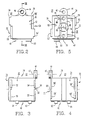
- Housing 22 is shown in detail in Figures 2 through 8, with Figures 2, 3, 4 and 5 being elevational views of a front portion 30, a first or left side 32 in the orientation shown, a second or right side 34, and a rear 36 portion, respectively.
- Figures 6 and 7 illustrate top and bottoms 38 and 40, respectively.
- Figure 8 is a cross sectional view of housing 22 taken between and in the direction of arrows VIII-VIII in Figure 2.
- housing 22 may be inverted from the orientation shown, and thus the top 38 and bottom 40 of Figures 6 and 7 refer to the orientation of housing 22 shown in Figure 2.
- reference 38 would refer to a bottom side and reference would refer to a top side.
- front side 30 of housing 22 includes a major flat front surface 42 which is substantially square in configuration. Surface 42 is aligned with the like front surfaces of other display modules in multi-unit displays. Also clearly shown in Figure 2 is a mounting projection 44 which extends outwardly from top 38. Mounting projection 44 has an opening 46 having a central axis 47. Opening 46 is adapted to receive a mounting stud attached to a face plate, such as mounting stud 48 shown fixed to a face plate 50 in Figure 11, which will be hereinafter described in detail.
- Each housing 22 has a single mounting projection 44, with the housings 22 being oriented in multi-unit displays such that mounting projections 44 are disposed on opposite sides of the display for firm support to a face plate, such as face plate 50.
- Figures 3 and 4 illustrate the first and second sides 32 and 34, respectively, which contain male and female dovetail extrusions for quickly joining adjacent housings.
- the first side 32 includes first and second male extrusions, projections or outward extensions 52 and 54, respectively, and first and second female extrusions, recesses or grooves 56 and 58, respectively.
- Male extension 52 starts near top 38 and runs about one-third of the way towards bottom 40, in closely spaced parallel relation with rear 36.
- the female groove 56 starts at, or closely adjacent to, the termination of male extension 52 and continues in the same direction as the male extension until reaching bottom 40.
- male extension 52 has dove-tail shaped cross section, expanding outwardly on both sides at an angle of about 10 degrees.
- Female groove 56 has a complementary dove tail shape for receiving the dove tail configuration of male extension 52.
- Male projection 54 has one side aligned with front surface 42, and as shown in Figures 6 and 7, only the side of projection 54 which is opposite to front surface 42 has a ten degree expansion.
- female recess 58 also intersects the front surface 42, and as shown in Figure 7 it has one side sloped at the 10 degree angle, as it is open on the side which intersects front surface 42.
- the second side 34 includes first and second male extrusions, projections or extensions 52′ and 54′, and first and second female extrusions, recesses or grooves 56′ and 58′.
- the male and female extrusions on the second side 34 are given the same reference numerals as those on the first side 32, except for a prime mark, as the like numbered male and female extrusions are in 180 degree rotational symmetry about a longitudinal axis 60.
- Axis 60 is parallel with axis 47 associated with opening 46 which receives a mounting stud 48.
- male extrusion 52 When housing 22 is rotated 180 degrees about axis 60 male extrusion 52 will move into the exact position formerly occupied by male extrusion 52′, and male extrusion 52′ will move into the exact position formerly occupied by male extrusion 52.
- adjacent housings may be interlocked by joining side 34 with side 32, with both modules having the same orientation; and, adjacent housings may be interlocked by joining side 34 with side 34, or side 32 with side 32, with one module being inverted or rotated 180 degrees about axis 60 relative to the orientation of the other module.
- bottom 40 has first and second male projections 62 and 64 disposed in spaced relation in a direction from the front 30 to the back 36. They are disposed on a side of central axis 60 which is adjacent to side 34 of housing 22. In like locations on the other side of central axis 60, i.e., adjacent to side 32, bottom 40 defines first and second recesses or openings 66 and 68, which openings are sized to snugly receive male projections 62 and 64, respectively, when the bottoms 40 of two housings 22 are placed in contacting relation. Openings 70 and 72 in bottom 40 are for ventilation.
- sides 32 are joined to sides 34 to create a row of like oriented modules, and this row may be placed upon a second row of like oriented modules, to form a cluster of modules, by inverting one row relative to the other, with the male projections 62 and 64 cooperating with openings 66 and 68 to help interlock vertically adjacent rows of the cluster.
- Top 38 is completely open for superior ventilation, with top 38 being defined by the ends of front portion 30, rear portion 36 and the first and second sides 32 and 34.
- Rear 36 portion defines a central opening 74 for receiving lamp module 28, and first and second openings 76 and 78 for receiving threaded bushings, such as bushing 80 shown in Figure 1.
- openings 76 and 78 are stepped, having a smaller diameter adjacent to the outer surface of rear 36, and bushings 80 are stepped.
- Bushings 80 are pressed into openings 76 and 78 from within the cavity 81 defined by the front 30, rear 36, sides 32 and 34 and bottom 40, so they cannot pull out when threadably engaged by a screw, such as screw 82 shown in Figure 1.
- Openings 83 and 84 in rear 36 aid ventilation.
- Raised portions 86, 88, 90 and 92 provide locating guides for lamp engaging contacts 94 and 94′ shown in Figure 1.
- the first assembly 24 includes threaded bushing 80, which is fixed in opening 76, lamp engaging contact 94, and screw 82 which fixes contact 94 in the proper location, aided by guides 86 and 88. Screw 82 also has a captured square washer 96 which provides room for a wire when screw 82 is not tightened, to facilitate wiring of the lamp contacts. Thus, screw 82 provides the dual function of securing a lamp engaging contact 94 and an electrical wire for energizing the contact.
- Lamp module 28 includes a lamp 98 and a lamp holder 100, with lamp 98 being energized by contacts 94 and 94′ simply by pushing the lamp 98 and lamp holder 100 into opening 74 in rear 36 of housing 22.
- lamp 98 which enters cavity 81 in its operative position, is easily replaced, without tools, simply by pulling lamp holder 100 from the rear of housing 22.
- Heat generated by lamp 98 is quickly dissipated by the open construction of housing 22, with the open top 34 remaining unobstructed in any multiple unit configuration of the modules 20.
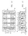
- FIGs 9, 10 and 11 illustrate a first multiple unit embodiment of the invention, in which modules 20 are assembled in a bar, serial string or row 101 to form a display or indicator 102.
- Figure 9 is a plan view of display 102
- Figure 10 is a rear view
- Figure 11 is an exploded perspective view.
- alternate modules are inverted to place mounting projections 44 on both the top and bottom of the row for firm support of the row in face plate 50.
- row 101 if the first module at the left hand end is to have mounting projection 44 on the bottom of the row, side 32 is engaged with side 32 of the next adjacent module by aligning male extrusion 52 of the second module with female extrusion 56 of the first module, and by aligning male extrusion 54 of the second module with the female extrusion 58 of the first module, and then pushing the two modules together until the top and bottom edges are aligned.
- the third module from the left is inverted and its side 34 is engaged with side 34 of the second module by engaging male extrusion 52′ with female extrusion 56′, and by engaging male extrusion 54′ with female extrusion 58′. Any number of modules 20 may be joined in this manner. Of course, it is not necessary to invert alternate modules, with any pattern of mounting projections being suitable as long as adequate support is provided for row 101 on face plate 50.
- Display 102 simulates a digital display, and it is not necessary or even desirable to punch an opening in face plate 50 for each digit.
- An aesthetic display is provided, according to the teachings of the invention by providing a single opening 104 in face plate 50 in a rectangular configuration with corresponds to the length of row 101.
- Face plate 50 may be formed of any suitable material, such as stainless steel, brass, and the like, and it may be a separate component for mounting above an elevator hatch door, or it may be part of a panel or wall, as desired, according to the function display 102 is to provide.
- Face plate 50 has outer and inner sides 106 and 108, with a plurality of studs 48 being fixed to the inner side 108. When face plate 50 is formed of metal, studs 48 may be stud welded to inner surface 108.
- a dark translucent plastic lens 110 such as red, for example, is provided which has a projection 112 sized to snugly enter opening 104 in face plate 50, and a flange 114.
- the depth of projection 112 is selected to match the thickness of face plate 50, to enable flange 114 to be pressed tightly against inner surface 108.
- Indicia to be selectively illuminated by modules 20 may be provided by a thin indicia bearing member 116 having the desired indicia in the form of openings in member 116; or, in the form of light transmissive numbers or letters surrounded by opaque material, such as a negative-like black plastic.
- the front surfaces 42 of each module 20 may be painted a dark color, such as black, except for the configuration of the indicia.
- the indicia may be formed by masking during the painting process, or by engraving surface 42 after the paint has dried.
- Nuts 118 are threadably engaged with studs 48 to hold the lens 110, indicia bearing member 116 and row 101 of modules 20 in assembled relation.
- FIGS 12 and 13 illustrate a multiple unit display 120 constructed according to another embodiment of the invention in which modules 20 are arranged in a cluster 121 having first and second superposed rows 122 and 124, respectively.
- modules 20 are arranged in a cluster 121 having first and second superposed rows 122 and 124, respectively.
- first and second superposed rows 122 and 124 respectively.
- mounting projections 44 are all disposed on the same side of the row.
- one row is inverted relative to the other row and placed with their sides 40 in contact such that projections 62 and 64 of each module enter openings 66 and 68 of the other module.
- the open tops 38 of the modules 20 in the first or upper row 122 face upwardly, and the open tops 38 of the modules 20 in the second or lower row 124 face downwardly, free of any obstruction, which, along with the large openings 83 and 84 in back 36 of housing 22, provide excellent ventilation for cluster 121.
- face plate 50′ may include a single opening 104′ for receiving a lens 110′.
- An indicia bearing member 116′ may be provided, or the indicia may be formed on the major front surfaces 42 of the module housings 22, as hereinbefore described.
- Additional mechanical support for holding the first and second rows 122 and 124 together may be provided by a thin electrically conductive member 126, such as a rectangular copper sheet, having a plurality of openings formed therein in a pattern which matches the locations of openings 78 in the housings 22 of the modules 20 which form cluster 121.
- electrically conductive member 126 is positioned with its openings aligned with openings 78 of the housings 22, and then screws 82′ are engaged with bushings 80′ disposed in openings 78.
- Electrical conductor 126 forms the common return line for the plurality of lamps 98 associated with cluster 121, requiring only one wire to be connected to any one of the screws 82′, greatly simplifying the wiring of the cluster, while providing additional mechanical support.
- a new and improved display module or lamp indicator unit 20 having a housing 22 molded of a translucent plastic which may be assembled with like modules and a face plate to form a row or cluster, without any tools other than a screw driver and a nut driver. Easy access is provided to the electrical wiring, and lamp bulbs are easily replaced.
- the multiple unit embodiments only require a single opening, regardless of the number of modules in the display or indicator. Thus, in an elevator position indicator, for example, one number would be illuminated somewhere on the surface of the otherwise dark lens.
Landscapes
- Physics & Mathematics (AREA)
- General Physics & Mathematics (AREA)
- Engineering & Computer Science (AREA)
- Theoretical Computer Science (AREA)
- Illuminated Signs And Luminous Advertising (AREA)
- Control Of Indicators Other Than Cathode Ray Tubes (AREA)
- Devices For Indicating Variable Information By Combining Individual Elements (AREA)
- Casings For Electric Apparatus (AREA)
- Coupling Device And Connection With Printed Circuit (AREA)
Priority Applications (1)
| Application Number | Priority Date | Filing Date | Title |
|---|---|---|---|
| AT89122295T ATE102379T1 (de) | 1988-12-22 | 1989-12-02 | Anzeigemodul und aus mehreren solcher anzeigemodulen bestehende anzeigevorrichtung. |
Applications Claiming Priority (2)
| Application Number | Priority Date | Filing Date | Title |
|---|---|---|---|
| US288195 | 1988-12-22 | ||
| US07/288,195 US4988986A (en) | 1988-12-22 | 1988-12-22 | Display module and multiple unit display constructed of such display modules |
Publications (3)
| Publication Number | Publication Date |
|---|---|
| EP0374561A2 true EP0374561A2 (de) | 1990-06-27 |
| EP0374561A3 EP0374561A3 (de) | 1991-03-27 |
| EP0374561B1 EP0374561B1 (de) | 1994-03-02 |
Family
ID=23106144
Family Applications (1)
| Application Number | Title | Priority Date | Filing Date |
|---|---|---|---|
| EP89122295A Expired - Lifetime EP0374561B1 (de) | 1988-12-22 | 1989-12-02 | Anzeigemodul und aus mehreren solcher Anzeigemodulen bestehende Anzeigevorrichtung |
Country Status (7)
| Country | Link |
|---|---|
| US (1) | US4988986A (de) |
| EP (1) | EP0374561B1 (de) |
| JP (1) | JPH02226187A (de) |
| AT (1) | ATE102379T1 (de) |
| CA (1) | CA2006513A1 (de) |
| DE (1) | DE68913465T2 (de) |
| ES (1) | ES2051969T3 (de) |
Cited By (3)
| Publication number | Priority date | Publication date | Assignee | Title |
|---|---|---|---|---|
| WO1992021120A1 (en) * | 1991-05-13 | 1992-11-26 | Interfax Ab | Display unit and light box therefor |
| WO1998040608A3 (en) * | 1997-03-12 | 1998-12-03 | Pita Witehira | A modular machine |
| WO2000062646A1 (en) * | 1999-04-15 | 2000-10-26 | Compagnucci - S.P.A. | Lighting modular panel for modular kitchen furniture |
Families Citing this family (5)
| Publication number | Priority date | Publication date | Assignee | Title |
|---|---|---|---|---|
| CA2152715C (en) * | 1995-06-27 | 1997-12-02 | Shu Wing Yuen | Illuminated house number |
| US7810263B2 (en) * | 2006-03-26 | 2010-10-12 | Lansa Sa | Back-lighted prismatic module price display system |
| CN101877949A (zh) * | 2009-04-30 | 2010-11-03 | 深圳富泰宏精密工业有限公司 | 便携式电子装置壳体组件 |
| USD933131S1 (en) * | 2020-01-07 | 2021-10-12 | Locomocean Limited | Tile |
| USD933130S1 (en) * | 2020-01-07 | 2021-10-12 | Locomocean Limited | Tile |
Family Cites Families (19)
| Publication number | Priority date | Publication date | Assignee | Title |
|---|---|---|---|---|
| US1108999A (en) * | 1914-03-06 | 1914-09-01 | Chicago Signal Company | Annunciator-cabinet. |
| US1879801A (en) * | 1926-04-06 | 1932-09-27 | Otis Elevator Co | Position indicator for elevators |
| US1878872A (en) * | 1929-01-21 | 1932-09-20 | Otis Elevator Co | Elevator indicator |
| FR802730A (fr) * | 1936-02-20 | 1936-09-14 | Telephonie Ind & Commerciale S | Tableau de signalisation lumineuse |
| GB465230A (en) * | 1936-06-03 | 1937-05-04 | Wilhelm Grothe | Improvements in electrically-operated indicators |
| US2925592A (en) * | 1958-12-09 | 1960-02-16 | Marco Ind Company | Multiple unit indicator with individual testing system |
| US3080554A (en) * | 1961-01-25 | 1963-03-05 | Marco Ind Company | Modular type indicator |
| GB1002306A (en) * | 1961-07-06 | 1965-08-25 | Communications Patents Ltd | Improvements in or relating to back-lighted display panels |
| US3268889A (en) * | 1964-04-20 | 1966-08-23 | Radar Relay Inc | Indicator unit and switch |
| FR2096289A5 (de) * | 1970-06-12 | 1972-02-11 | Comont Spa | |
| US3742446A (en) * | 1971-08-26 | 1973-06-26 | Staco Switch Inc | Modular light display panel |
| FR2223936B1 (de) * | 1973-03-28 | 1978-04-21 | Francaise App Elect Mesure | |
| US4336673A (en) * | 1980-09-05 | 1982-06-29 | Monitronik Ltee. | Mosaic display panel |
| US4471350A (en) * | 1980-09-12 | 1984-09-11 | Chow Shing C | Display device using a discharge lamp |
| ES269889Y (es) * | 1983-01-21 | 1984-02-01 | Componente sinoptico de mosaico. | |
| US4504713A (en) * | 1983-07-13 | 1985-03-12 | Adams Elevator Equipment Company | Push button electrical switch assembly |
| US4723119A (en) * | 1984-05-07 | 1988-02-02 | Futaba Denshi Kogyo Kabushiki Kaisha | Large-sized color display device |
| KR900008072B1 (ko) * | 1986-07-15 | 1990-10-31 | 미쓰비시전기 주식회사 | 표시장치 |
| US4820956A (en) * | 1987-10-02 | 1989-04-11 | Integrated Systems Engineering, Inc. | Light matrix display system |
-
1988
- 1988-12-22 US US07/288,195 patent/US4988986A/en not_active Expired - Fee Related
-
1989
- 1989-12-02 AT AT89122295T patent/ATE102379T1/de not_active IP Right Cessation
- 1989-12-02 EP EP89122295A patent/EP0374561B1/de not_active Expired - Lifetime
- 1989-12-02 ES ES89122295T patent/ES2051969T3/es not_active Expired - Lifetime
- 1989-12-02 DE DE68913465T patent/DE68913465T2/de not_active Expired - Fee Related
- 1989-12-21 JP JP1332472A patent/JPH02226187A/ja active Pending
- 1989-12-22 CA CA002006513A patent/CA2006513A1/en not_active Abandoned
Cited By (4)
| Publication number | Priority date | Publication date | Assignee | Title |
|---|---|---|---|---|
| WO1992021120A1 (en) * | 1991-05-13 | 1992-11-26 | Interfax Ab | Display unit and light box therefor |
| US5276598A (en) * | 1991-05-13 | 1994-01-04 | Interfax Ab | Display unit and light box therefor |
| WO1998040608A3 (en) * | 1997-03-12 | 1998-12-03 | Pita Witehira | A modular machine |
| WO2000062646A1 (en) * | 1999-04-15 | 2000-10-26 | Compagnucci - S.P.A. | Lighting modular panel for modular kitchen furniture |
Also Published As
| Publication number | Publication date |
|---|---|
| JPH02226187A (ja) | 1990-09-07 |
| DE68913465T2 (de) | 1994-07-21 |
| ATE102379T1 (de) | 1994-03-15 |
| ES2051969T3 (es) | 1994-07-01 |
| US4988986A (en) | 1991-01-29 |
| EP0374561A3 (de) | 1991-03-27 |
| CA2006513A1 (en) | 1990-06-22 |
| DE68913465D1 (de) | 1994-04-07 |
| EP0374561B1 (de) | 1994-03-02 |
Similar Documents
| Publication | Publication Date | Title |
|---|---|---|
| US4532579A (en) | Illuminated interconnectable sign module | |
| US5963126A (en) | Visual signaling device | |
| US4667277A (en) | Indicator lamp assembly | |
| US6422716B2 (en) | Modular led assembly | |
| US5729925A (en) | Illuminated emergency sign utilizing LED units | |
| US5539623A (en) | Lighting device used in an exit sign | |
| US6257736B1 (en) | Luminous element with contact lugs having longitudinal slots for holding electrical contacts of devices in first and second planes | |
| AU708769B2 (en) | Push-in bulb base for bayonet-type bulb sockets | |
| US4988986A (en) | Display module and multiple unit display constructed of such display modules | |
| CA1304577C (en) | Glass block illuminated display | |
| EP0936400A2 (de) | Mehrere leuchtemittierende Dioden enthaltendes Modul | |
| US4754380A (en) | Characters for illuminated display signs | |
| US20030030567A1 (en) | Flexible functionality of stack light | |
| US4210772A (en) | Pre-wired electrical circuit box | |
| CA2184977A1 (en) | Stop sign housing with flashing lights | |
| GB2287141A (en) | An electrical connector assembly | |
| US4949487A (en) | Illuminated display | |
| US4213665A (en) | Electrical connector | |
| US6083012A (en) | Rear combination lamp | |
| US6019486A (en) | Lighting device | |
| US4859198A (en) | Contact assembly | |
| GB2081516A (en) | A spacing and fixing element for electronic components | |
| JPH0656912U (ja) | 車輌用灯具 | |
| JPS5916681B2 (ja) | 信号灯具 | |
| US4793815A (en) | Electrical connector |
Legal Events
| Date | Code | Title | Description |
|---|---|---|---|
| PUAI | Public reference made under article 153(3) epc to a published international application that has entered the european phase |
Free format text: ORIGINAL CODE: 0009012 |
|
| AK | Designated contracting states |
Kind code of ref document: A2 Designated state(s): AT CH DE ES FR GB IT LI |
|
| PUAL | Search report despatched |
Free format text: ORIGINAL CODE: 0009013 |
|
| AK | Designated contracting states |
Kind code of ref document: A3 Designated state(s): AT CH DE ES FR GB IT LI |
|
| 17P | Request for examination filed |
Effective date: 19910829 |
|
| 17Q | First examination report despatched |
Effective date: 19930527 |
|
| GRAA | (expected) grant |
Free format text: ORIGINAL CODE: 0009210 |
|
| AK | Designated contracting states |
Kind code of ref document: B1 Designated state(s): AT CH DE ES FR GB IT LI |
|
| REF | Corresponds to: |
Ref document number: 102379 Country of ref document: AT Date of ref document: 19940315 Kind code of ref document: T |
|
| REF | Corresponds to: |
Ref document number: 68913465 Country of ref document: DE Date of ref document: 19940407 |
|
| ITF | It: translation for a ep patent filed | ||
| ET | Fr: translation filed | ||
| REG | Reference to a national code |
Ref country code: ES Ref legal event code: FG2A Ref document number: 2051969 Country of ref document: ES Kind code of ref document: T3 |
|
| PLBE | No opposition filed within time limit |
Free format text: ORIGINAL CODE: 0009261 |
|
| STAA | Information on the status of an ep patent application or granted ep patent |
Free format text: STATUS: NO OPPOSITION FILED WITHIN TIME LIMIT |
|
| 26N | No opposition filed | ||
| PGFP | Annual fee paid to national office [announced via postgrant information from national office to epo] |
Ref country code: CH Payment date: 19950316 Year of fee payment: 6 |
|
| PGFP | Annual fee paid to national office [announced via postgrant information from national office to epo] |
Ref country code: GB Payment date: 19951127 Year of fee payment: 7 Ref country code: FR Payment date: 19951127 Year of fee payment: 7 |
|
| PGFP | Annual fee paid to national office [announced via postgrant information from national office to epo] |
Ref country code: ES Payment date: 19951130 Year of fee payment: 7 Ref country code: DE Payment date: 19951130 Year of fee payment: 7 |
|
| PGFP | Annual fee paid to national office [announced via postgrant information from national office to epo] |
Ref country code: AT Payment date: 19951201 Year of fee payment: 7 |
|
| PG25 | Lapsed in a contracting state [announced via postgrant information from national office to epo] |
Ref country code: LI Effective date: 19951231 Ref country code: CH Effective date: 19951231 |
|
| REG | Reference to a national code |
Ref country code: CH Ref legal event code: PL |
|
| PG25 | Lapsed in a contracting state [announced via postgrant information from national office to epo] |
Ref country code: GB Effective date: 19961202 Ref country code: AT Effective date: 19961202 |
|
| GBPC | Gb: european patent ceased through non-payment of renewal fee |
Effective date: 19961202 |
|
| PG25 | Lapsed in a contracting state [announced via postgrant information from national office to epo] |
Ref country code: FR Effective date: 19970829 |
|
| PG25 | Lapsed in a contracting state [announced via postgrant information from national office to epo] |
Ref country code: DE Effective date: 19970902 |
|
| REG | Reference to a national code |
Ref country code: FR Ref legal event code: ST |
|
| PG25 | Lapsed in a contracting state [announced via postgrant information from national office to epo] |
Ref country code: ES Free format text: LAPSE BECAUSE OF NON-PAYMENT OF DUE FEES Effective date: 19971203 |
|
| REG | Reference to a national code |
Ref country code: ES Ref legal event code: FD2A Effective date: 19980113 |
|
| PG25 | Lapsed in a contracting state [announced via postgrant information from national office to epo] |
Ref country code: IT Free format text: LAPSE BECAUSE OF NON-PAYMENT OF DUE FEES;WARNING: LAPSES OF ITALIAN PATENTS WITH EFFECTIVE DATE BEFORE 2007 MAY HAVE OCCURRED AT ANY TIME BEFORE 2007. THE CORRECT EFFECTIVE DATE MAY BE DIFFERENT FROM THE ONE RECORDED. Effective date: 20051202 |