EP0374585A1 - Verfahren zur Herstellung einer Oberflächenschicht aus Molybdän durch thermisches Spritzen - Google Patents
Verfahren zur Herstellung einer Oberflächenschicht aus Molybdän durch thermisches Spritzen Download PDFInfo
- Publication number
- EP0374585A1 EP0374585A1 EP89122474A EP89122474A EP0374585A1 EP 0374585 A1 EP0374585 A1 EP 0374585A1 EP 89122474 A EP89122474 A EP 89122474A EP 89122474 A EP89122474 A EP 89122474A EP 0374585 A1 EP0374585 A1 EP 0374585A1
- Authority
- EP
- European Patent Office
- Prior art keywords
- molybdenum
- spraying
- flame
- oxidized
- flame spraying
- Prior art date
- Legal status (The legal status is an assumption and is not a legal conclusion. Google has not performed a legal analysis and makes no representation as to the accuracy of the status listed.)
- Granted
Links
Images
Classifications
-
- C—CHEMISTRY; METALLURGY
- C23—COATING METALLIC MATERIAL; COATING MATERIAL WITH METALLIC MATERIAL; CHEMICAL SURFACE TREATMENT; DIFFUSION TREATMENT OF METALLIC MATERIAL; COATING BY VACUUM EVAPORATION, BY SPUTTERING, BY ION IMPLANTATION OR BY CHEMICAL VAPOUR DEPOSITION, IN GENERAL; INHIBITING CORROSION OF METALLIC MATERIAL OR INCRUSTATION IN GENERAL
- C23C—COATING METALLIC MATERIAL; COATING MATERIAL WITH METALLIC MATERIAL; SURFACE TREATMENT OF METALLIC MATERIAL BY DIFFUSION INTO THE SURFACE, BY CHEMICAL CONVERSION OR SUBSTITUTION; COATING BY VACUUM EVAPORATION, BY SPUTTERING, BY ION IMPLANTATION OR BY CHEMICAL VAPOUR DEPOSITION, IN GENERAL
- C23C4/00—Coating by spraying the coating material in the molten state, e.g. by flame, plasma or electric discharge
- C23C4/04—Coating by spraying the coating material in the molten state, e.g. by flame, plasma or electric discharge characterised by the coating material
- C23C4/06—Metallic material
- C23C4/08—Metallic material containing only metal elements
Definitions
- the invention relates to a method for producing a surface layer from molybdenum by thermal spraying.
- Molybdenum is known as an extremely wear-resistant material, and it is therefore the goal of many metal products to provide them with a high-quality molybdenum surface layer. Thermal spraying methods are also used for this purpose. The difficulties with the thermal spraying of molybdenum layers are due in particular to the fact that molybdenum has a very high melting point (2610 ° C.).
- the high melting temperature of the molybdenum results in the need for a certain minimum residence time of the spray particles in the melting zone, i.e. must be present in the plasma jet. As a consequence, the conveying speed of the molybdenum powder particles is limited. This leads to restrictions in the process design and quality restrictions in the layer to be applied. In addition, due to a lack of oxygen in the melting zone, there is no quality-promoting oxidation of the spray particles during melting due to the lack of oxygen. This also leads to a deterioration in the coating quality.
- molybdenum material used in the present invention it is known that it can be produced in oxidized or partially oxidized form, these states having a lower melting point than the pure form (up to below 1000 ° C.).
- the object of the present invention is to provide a thermal spraying process for the production of molybdenum layers which overcomes the disadvantages of the known processes and in particular allows greater flexibility in the process parameters compared to the known processes, which consequently leads to better molybdenum layer quality .
- the surface layer to be produced is produced by flame spraying or high-speed flame spraying with pre-oxidized or partially pre-oxidized molybdenum spray material.
- the autogenous spraying process can cause the spraying material to oxidize, which leads to greater hardness of the sprayed layer produced.
- a reducing effect can also be set.
- the pre-oxidized spray material often proves to be an advantage.
- a process design that leads to particularly high quality results is that the process pressures are selected in such a way that melt particle speeds greater than 250 m / sec., Preferably more than 300 m / sec.
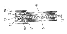
- the drawing shows a cross section through a flame spray burner head without showing the fuel gas supply and spray material supply in detail.
- the burner head has a centrally located combustion chamber 21 into which feed channels 22 for the combustion gas mixture, e.g. consisting of fuel gas and oxygen, open out with a somewhat conical orientation, so that the incoming, burning gas jets intersect in the combustion chamber 21 and form a flame 24.
- the carrier gas jet is guided into this flame through a central channel 23.
- the carrier gas jet contains the pre-oxidized molybdenum spray material.
- the spray material is melted in the flame 24 generated by the fuel gas and oxygen and the entire mixture of combustion gases, carrier gas and melted spray material is passed on through a main channel 25 adjoining the combustion chamber 21 and finally leaves the burner head in the form of a spray jet 27.
- a between An outer casing 28 of the burner head and the main duct wall and the duct 29 formed in the combustion chamber wall cools the burner head.
- This burner head is now operated according to the invention as follows:
- Powdery, completely pre-oxidized molybdenum is introduced into the combustion chamber 21 in a nitrogen stream through the central channel 23.
- the pressure of the nitrogen carrier gas is approximately 5 bar.
- the combustion chamber is supplied with hydrogen and oxygen in a somewhat sub-stoichiometric composition via the supply channels 22. This takes place at a pressure of approximately 4.5 bar.
- These process parameters produce a high spray particle speed, generally more than 300 m / sec.
- a sufficient melting of the spray material is achieved (grain size of the spray material is approximately 50 to 100 micrometers).
- the pre-oxidized, powdery molybdenum is at the same time partially reduced and melted when passing through the flame 24 and in this form strikes the workpiece surface to be coated. The result is a surface layer with particularly high hardness and adhesive tensile strength with low porosity.
- the flame spraying process according to the invention can also be carried out with other fuel gases, such as propane, propylene, acetylene, etc.
- the autogenous thermal spraying process according to the invention in contrast to plasma spraying, implies the advantages of an autogenous flame, while at the same time achieving a high degree of flexibility in the process parameters.
- the advantages of using higher process pressures in high-speed flame spraying, such as advantageously oxidized spray particles at high speed, should be emphasized.
Landscapes
- Chemical & Material Sciences (AREA)
- Engineering & Computer Science (AREA)
- Mechanical Engineering (AREA)
- Plasma & Fusion (AREA)
- Chemical Kinetics & Catalysis (AREA)
- Materials Engineering (AREA)
- Physics & Mathematics (AREA)
- Metallurgy (AREA)
- Organic Chemistry (AREA)
- Coating By Spraying Or Casting (AREA)
- Inorganic Compounds Of Heavy Metals (AREA)
- Chemically Coating (AREA)
- Application Of Or Painting With Fluid Materials (AREA)
Abstract
Description
- Die Erfindung betrifft ein Verfahren zur Herstellung einer Oberflächenschicht aus Molybdän durch thermisches Spritzen.
- Molybdän ist als hervorragend verschleißfester Werkstoff bekannt, und es ist deshalb bei vielen Metallprodukten das Ziel, diese mit einer hochwertigen Molybdän-Oberflächenschicht zu versehen. Dazu werden insbesondere auch thermische Spritzverfahren angewendet. Die Schwierigkeiten beim thermischen Aufspritzen von Molybdänschichten beruhen insbesondere darauf, daß Molybdän einen sehr hohen Schmelzpunkt (2610°C) besitzt.
- Es wurden bisher im wesentlichen zwei Methoden zum thermischen Spritzen von Molybdän angewendet: Zum einen ist es bekannt, Molybdänschichten mittels Plasmaspritzen herzustellen, d.h. pulverförmiges Molybdän wird mit Hilfe eines Trägergases in den Plasmastrahl eines Plasmabrenners geführt, schmilzt dort auf und die geschmolzenen Molybdänpartikel werden in dem vorhandenen Gasstrom auf die zu beschichtende Werkstückoberfläche weitertransportiert.
- Aus der hohen Schmelztemperatur des Molybdäns resultiert die Notwendigkeit, daß eine bestimmte Mindestverweilzeit der Spritzpartikel in der Aufschmelzzone, d.h. im Plasmastrahl, vorhanden sein muß. In der Konsequenz dessen ist die Beförderungsgeschwindigkeit der Molybdänpulverpartikel begrenzt. Dies führt zu Einschränkungen in der Verfahrensausgestaltung und Qualitätsbeschränkungen in der aufzubringenden Schicht. Darüber hinaus kommt es beim Plasmaspritzen aufgrund mangelnden Sauerstoffs in der Aufschmelzzone zu keiner qualitätsförderlichen Aufoxidation der Spritzpartikel während des Aufschmelzens. Dies führt ebenfalls zu einer Verschlechterung der Beschichtungsqualität.
- Neben dem Plasmaspritzen mit pulverförmigem Ausgangsmaterial ist es auch bekannt, Molybdänschichten mittels Flammspritzen mit draht- oder stabförmigem Ausgangsmaterial zu erzeugen. Dabei wird das Abschmelzen des Molybdäns vom Draht durch eine Brenngasflamme bewirkt und der Transport der Schmelzpartikel vom Draht zum Werkstück erfolgt ebenfalls mit einem Trägergasstrom. Aufgrund des hohen Schmelzpunkts des Molybdäns kann das Flammspritzen mit Molybdän nicht wie mit anderen Werkstoffen in Pulverform erfolgen, sondern das Flammspritzen von Molybdän ist bisher nur mit draht- oder stabförmigem Ausgangsmaterial möglich, da hierbei die Verweilzeit des Molybdäns in der Schmelzflamme steuerbar ist und ein ausreichendes Aufschmelzen erreicht wird. Dies bedeutet aber wiederum eine wesentliche flammspritztechnische Einschränkung, die ebenfalls Auswirkungen auf die Qualität der aufgebrachten Oberflächenschicht zur Konsequenz hat. Beispielsweise ist infolge der Spritzwerkstoffzugabe in Drahtform nur eine relativ niedrige Geschwindigkeit der Schmelzpartikel beim Auftreffen auf die Werkstückoberfläche erreichbar, da die Beschleunigung der Partikel nur zwischen dem Abschmelzvorgang und dem Auftreffen auf der Werkstückoberfläche stattfinden kann, was zu niedrigen Haftzugwerten und großer Porösität der aufgebrachten Schicht führt.
- Im Hinblick auf den bei der vorliegenden Erfindung zur Anwendung kommenden Werkstoff Molybdän ist andererseits bekannt, daß dieser in oxidierter oder teilweise oxidierter Form herstellbar ist, wobei diese Zustandsformen im Vergleich zur Reinform einen erniedrigten Schmelzpunkt besitzen (bis unter 1000 °C).
- Die Aufgabenstellung der vorliegenden Erfindung besteht nun darin, ein thermisches Spritzverfahren zur Erzeugung von Molybdänschichten anzugeben, das die Nachteile der bekannten Verfahren überwindet und insbesondere eine im Vergleich zu den bekannten Verfahren größere Flexibilität in den Verfahrensparametern zuläßt, die in der Konsequenz zu einer besseren Molybdänschichtqualität führt.
- Diese Aufgabe wird erfindungsgemäß dadurch gelöst, daß die zu erzeugende Oberflächenschicht durch Flammspritzen oder Hochgeschwindigkeitsflammspritzen mit voroxidiertem oder teilweise voroxidiertem Molybdän-Spritzwerkstoff hergestellt wird.
- Dadurch daß niedrigschmelzendes, ganz oder teilweise voroxidiertes Molybdän als Spritzwerkstoff verwendet wird, erreicht man insbesondere bei der Anwendung beim Flammspritzen oder Hochgeschwindigkeitsflammspritzen besondere Vorteile und eine erheblich vergrößerte Flexibilität in der Verfahrensweise. Zunächst besteht jetzt die Möglichkeit, auch beim Flammspritzen und Hochgeschwindigkeitsflammspritzen pulverförmigen Spritzwerkstoff einzusetzen. Darüber hinaus ist es jetzt möglich, sowohl bei der Verwendung von drahtförmigem als auch bei der Verwendung von pulverförmigem voroxidiertem Molybdän mit höheren Treibgasdrücken und/oder Brenngasdrücken zu arbeiten als bei den bekannten Verfahren. Darüber hinaus ergeben sich aus dem Anwendung der Flammspritzmethode die grundsätzlichen Vorteile, die bei der Anwendung einer autogenen Flamme folgen, nämlich die unterschiedliche Einstellbarkeit der Flamme und die daraus folgende Beeinflußbarkeit des Spritzvorgangs. Beispielsweise kann mit dem autogenen Spritzverfahren im Gegensatz zum Plasmaspritzen eine Aufoxidation des Spritzwerkstoffs erreicht werden, die zu größeren Härten der erzeugten Spritzschicht führt. Ebenso ist eine reduzierende Wirkung einstellbar. Diesbezüglich erweist sich vielfach auch der bereits voroxidierte Spritzwerkstoff als Vorteil.
- Vorteilhaft ist insbesondere die Ausführung des erfindungsgemäßen Verfahrens mit pulverförmigem Spritzwerkstoff. Diese Ausgestaltung erlaubt sowohl eine hohe Flexibilität im Hinblick auf die zu wählenden Verfahrensdrücke bezüglich Brenngas und Trägergas sowie die Möglichkeit, verschiedene Korngrößen des Spritzwerkstoffs anzuwenden.
- Eine Verfahrensausgestaltung, die zu qualitativ besonders hochwertigen Ergebnissen führt, besteht darin, daß die Verfahrensdrücke derart gewählt werden, daß sich Schmelzpartikelgeschwindigkeiten größer als 250 m/sec., vorzugsweise mehr als 300 m/sec., ergeben.
- Anhand der schematischen Zeichnung soll im folgenden das erfindungsgemäße Verfahren beispielhaft näher beschrieben werden.
- In der Zeichnung ist ein Querschnitt durch einen Flammspritzbrennerkopf dargestellt, ohne die Brenngasversorgung und Spritzmaterialzufuhr im einzelnen zu zeigen. Der Brennerkopf besitzt eine zentral angeordnete Brennkammer 21, in die Zufuhrkanäle 22 für das Verbrennungsgasgemisch, z.B. bestehend aus Brenngas und Sauerstoff, mit etwas konischer Ausrichtung einmünden, so daß sich die eintretenden, brennenden Gasstrahlen in der Brennkammer 21 schneiden und eine Flamme 24 bilden. In diese Flamme hinein wird der Trägergasstrahl durch einen Zentralkanal 23 geführt. Der Trägergasstrahl enthält das voroxidierte Molybdän-Spritzmaterial. Das Spritzmaterial wird in der vom Brenngas und Sauerstoff erzeugten Flamme 24 geschmolzen und die gesamte Mischung aus Verbrennungsgasen, Trägergas und geschmolzenem Spritzmaterial wird durch einen sich an die Brennkammer 21 anschließenden Hauptkanal 25 weitergeleitet und verläßt den Brennerkopf schließlich in Form eines Spritzstrahls 27. Durch einen zwischen einer äußeren Umhüllung 28 des Brennerkopfes und der Hauptkanalwand sowie der Brennkammerwand entstehenden Kanal 29 wird der Brennerkopf gekühlt.
- Dieser Brennerkopf wird nun erfindungsgemäß wie folgt betrieben:
- Durch den Zentralkanal 23 wird pulverförmiges, vollständig voroxidiertes Molybdän in einem Stickstoffstrom in die Brennkammer 21 eingeführt. Der Druck des Stickstoffträgergases liegt hierbei in einer vorteilhaften Ausführung etwa in der Höhe von 5 bar. Andererseits wird der Brennkammer über die Zufuhrkanäle 22 Wasserstoff und Sauerstoff in etwas unterstöchiometrischer Zusammensetzung zugeführt. Dies erfolgt mit einem Druck von etwa 4,5 bar. Durch diese Verfahrensparameter wird eine hohe Spritzpartikelgeschwindigkeit, in aller Regel über 300 m/sec., erzeugt und andererseits auch ein ausreichendes Aufschmelzen des Spritzmaterials erreicht (Körngröße des Spritzmaterials etwa 50 bis 100 Mikrometer). Das voroxidierte, pulverförmige Molybdän wird beim Durchlaufen der Flamme 24 gleichzeitig teilweise reduziert und geschmolzen und trifft in dieser Form auf die zu beschichtende Werkstückoberfläche auf. Es ergibt sich eine Oberflächenschicht mit besonders hoher Härte und Haftzugfestigkeit bei geringer Porösität.
- Das erfindungsgemäße Flammspritzverfahren kann auch mit anderen Brenngasen, wie Propan, Propylen, Acetylen usw., ausgeführt werden.
- Zusammenfassend sei nochmals festgehalten, daß das erfindungsgemäße autogene thermische Spritzverfahren im Gegensatz zum Plasmaspritzen die Vorteile einer autogenen Flamme impliziert, wobei gleichzeitig eine hohe Flexibilität in den Verfahrensparametern erreicht ist. Insbesondere die Vorteile bei der Anwendung höherer Verfahrensdrücke beim Hochgeschwindigkeitsflammspritzen, wie vorteilhaft aufoxidierte Spritzpartikel mit hoher Geschwindigkeit, sind hervorzuheben.
Claims (3)
Priority Applications (1)
| Application Number | Priority Date | Filing Date | Title |
|---|---|---|---|
| AT89122474T ATE96849T1 (de) | 1988-12-15 | 1989-12-06 | Verfahren zur herstellung einer oberflaechenschicht aus molybdaen durch thermisches spritzen. |
Applications Claiming Priority (2)
| Application Number | Priority Date | Filing Date | Title |
|---|---|---|---|
| DE3842263A DE3842263C1 (de) | 1988-12-15 | 1988-12-15 | |
| DE3842263 | 1988-12-15 |
Publications (2)
| Publication Number | Publication Date |
|---|---|
| EP0374585A1 true EP0374585A1 (de) | 1990-06-27 |
| EP0374585B1 EP0374585B1 (de) | 1993-11-03 |
Family
ID=6369249
Family Applications (1)
| Application Number | Title | Priority Date | Filing Date |
|---|---|---|---|
| EP89122474A Expired - Lifetime EP0374585B1 (de) | 1988-12-15 | 1989-12-06 | Verfahren zur Herstellung einer Oberflächenschicht aus Molybdän durch thermisches Spritzen |
Country Status (5)
| Country | Link |
|---|---|
| EP (1) | EP0374585B1 (de) |
| AT (1) | ATE96849T1 (de) |
| AU (1) | AU617563B2 (de) |
| DE (2) | DE3842263C1 (de) |
| ES (1) | ES2047646T3 (de) |
Citations (7)
| Publication number | Priority date | Publication date | Assignee | Title |
|---|---|---|---|---|
| FR1148292A (fr) * | 1955-05-02 | 1957-12-05 | Union Carbide & Carbon Corp | Procédé d'application de matières à point de fusion élevé à l'état pulvérisé |
| GB1102845A (en) * | 1965-10-23 | 1968-02-14 | American Metal Climax Inc | Improvements relating to coating compositions containing molybdenum |
| DE2312810A1 (de) * | 1973-03-15 | 1974-09-19 | Goetzewerke | Legierung bzw. pulvergemisch zur herstellung von verschleissfesten schichten durch auftragschweissen |
| US4146388A (en) * | 1977-12-08 | 1979-03-27 | Gte Sylvania Incorporated | Molybdenum plasma spray powder, process for producing said powder, and coatings made therefrom |
| EP0009210A2 (de) * | 1978-09-23 | 1980-04-02 | Goetze Ag | Spritzpulver für die Herstellung verschleissfester Beschichtungen auf den Laufflächen von Kolbenringen oder Dichtleisten |
| US4416421A (en) * | 1980-10-09 | 1983-11-22 | Browning Engineering Corporation | Highly concentrated supersonic liquified material flame spray method and apparatus |
| EP0233574A2 (de) * | 1986-02-12 | 1987-08-26 | GTE Products Corporation | Verfahren zur Überwachung des Sauerstoffgehaltes in einem agglomerierten Molybdänpulver |
Family Cites Families (2)
| Publication number | Priority date | Publication date | Assignee | Title |
|---|---|---|---|---|
| US3973948A (en) * | 1973-11-12 | 1976-08-10 | Gte Sylvania Incorporated | Free flowing powder and process for producing it |
| US4684400A (en) * | 1986-02-20 | 1987-08-04 | Gte Products Corporation | Method for controlling the oxygen content in agglomerated molybdenum powders |
-
1988
- 1988-12-15 DE DE3842263A patent/DE3842263C1/de not_active Expired - Fee Related
-
1989
- 1989-12-06 EP EP89122474A patent/EP0374585B1/de not_active Expired - Lifetime
- 1989-12-06 AT AT89122474T patent/ATE96849T1/de not_active IP Right Cessation
- 1989-12-06 DE DE89122474T patent/DE58906109D1/de not_active Expired - Fee Related
- 1989-12-06 ES ES89122474T patent/ES2047646T3/es not_active Expired - Lifetime
- 1989-12-13 AU AU46185/89A patent/AU617563B2/en not_active Ceased
Patent Citations (7)
| Publication number | Priority date | Publication date | Assignee | Title |
|---|---|---|---|---|
| FR1148292A (fr) * | 1955-05-02 | 1957-12-05 | Union Carbide & Carbon Corp | Procédé d'application de matières à point de fusion élevé à l'état pulvérisé |
| GB1102845A (en) * | 1965-10-23 | 1968-02-14 | American Metal Climax Inc | Improvements relating to coating compositions containing molybdenum |
| DE2312810A1 (de) * | 1973-03-15 | 1974-09-19 | Goetzewerke | Legierung bzw. pulvergemisch zur herstellung von verschleissfesten schichten durch auftragschweissen |
| US4146388A (en) * | 1977-12-08 | 1979-03-27 | Gte Sylvania Incorporated | Molybdenum plasma spray powder, process for producing said powder, and coatings made therefrom |
| EP0009210A2 (de) * | 1978-09-23 | 1980-04-02 | Goetze Ag | Spritzpulver für die Herstellung verschleissfester Beschichtungen auf den Laufflächen von Kolbenringen oder Dichtleisten |
| US4416421A (en) * | 1980-10-09 | 1983-11-22 | Browning Engineering Corporation | Highly concentrated supersonic liquified material flame spray method and apparatus |
| EP0233574A2 (de) * | 1986-02-12 | 1987-08-26 | GTE Products Corporation | Verfahren zur Überwachung des Sauerstoffgehaltes in einem agglomerierten Molybdänpulver |
Also Published As
| Publication number | Publication date |
|---|---|
| ES2047646T3 (es) | 1994-03-01 |
| AU4618589A (en) | 1990-06-21 |
| AU617563B2 (en) | 1991-11-28 |
| ATE96849T1 (de) | 1993-11-15 |
| DE58906109D1 (de) | 1993-12-09 |
| EP0374585B1 (de) | 1993-11-03 |
| DE3842263C1 (de) | 1990-06-13 |
Similar Documents
| Publication | Publication Date | Title |
|---|---|---|
| DE69701877T2 (de) | Verfahren und vorrichtung zum thermischen spritzen | |
| EP0915184A1 (de) | Verfahren zur Herstellung einer keramischen Schicht auf einem metallischen Grundwerkstoff | |
| DE4031489C2 (de) | ||
| EP3314033B1 (de) | Eisenbasierte legierung zur herstellung thermisch aufgebrachter verschleissschutzschichten | |
| DE4239903C1 (de) | Injektor-Mundstück für Brenneraggregate | |
| DE4236911C1 (de) | Thermisches Spritzverfahren zur Erzeugung von Oberflächenbeschichtungen | |
| EP0458018B1 (de) | Verfahren und Vorrichtung zum Hochgeschwindigkeitsflammspritzen von hochschmelzenden draht- und pulverförmigen Zusatzwerkstoffen zum Beschichten von Oberflächen | |
| DE3842263C1 (de) | ||
| WO1997012743A1 (de) | Rückstromsperre für eine spritzeinheit einer spritzgiessmaschine | |
| EP0263469A1 (de) | Verfahren zum thermischen Beschichten von Oberflächen | |
| DE102013112809A1 (de) | Verfahren zur Herstellung einer gespritzten Zylinderlauffläche eines Zylinderkurbelgehäuses einer Verbrennungskraftmaschine sowie derartiges Zylinderkurbelgehäuse | |
| EP0458182A2 (de) | Verfahren und Vorrichtung zum Laserstrahlbrennschneiden | |
| DE3533966C1 (de) | Verfahren und Lichtbogenspritzduese zum Beschichten von Werkstueckoberflaechen durch Schmelzen von Draehten in einem elektrischen Lichtbogen | |
| EP0120373A1 (de) | Verfahren zum Beschichten von Oberflächen mit Russ | |
| EP0911423A1 (de) | Verbinden von Werkstücken | |
| DE102017218580A1 (de) | Verfahren zum Aufbringen einer Schicht auf ein Bauteil und Bauteil hergestellt nach dem Verfahren | |
| DE4219992C2 (de) | Thermisches Spritzverfahren und Spritz- und Beschleunigungsdüse zur Erzeugung von Metallschichten | |
| DE2519916C3 (de) | Verfahren und Vorrichtung zur Erhöhung der Schnittgeschwindigkeit und Verbesserung der Schnittqualität beim Brennschneiden mittels Sauerstoff-Strahl | |
| EP0647497B1 (de) | Verfahren zum Legieren eines Werkstückes unter Einsatz von Laserstrahlung | |
| EP0189053A1 (de) | Verfahren zum Auftragen von Lot | |
| EP0517191A1 (de) | Verfahren zur Herstellung einer Gleitlageroberflächenschicht aus üblichen Lagermetallen | |
| WO1993023585A1 (de) | Verfahren und vorrichtung zum thermischen spritzen von pulver- oder draht- oder stabförmigen spritzzusatzwerkstoffen | |
| DE2459437A1 (de) | Lichtbogenschweissverfahren sowie lichtbogenschweissgeraet zur durchfuehrung des verfahrens | |
| DE4334610A1 (de) | Verfahren zur Behandlung einer Oberfläche durch thermisches Spritzen | |
| EP3969204A1 (de) | BESCHICHTETE, VERSCHLEIßTRÄCHTIGE METALLSUBSTRATE UND VERFAHREN ZU IHRER HERSTELLUNG |
Legal Events
| Date | Code | Title | Description |
|---|---|---|---|
| PUAI | Public reference made under article 153(3) epc to a published international application that has entered the european phase |
Free format text: ORIGINAL CODE: 0009012 |
|
| AK | Designated contracting states |
Kind code of ref document: A1 Designated state(s): AT BE CH DE ES FR GR IT LI NL |
|
| 17P | Request for examination filed |
Effective date: 19901208 |
|
| 17Q | First examination report despatched |
Effective date: 19920303 |
|
| ITF | It: translation for a ep patent filed | ||
| GRAA | (expected) grant |
Free format text: ORIGINAL CODE: 0009210 |
|
| AK | Designated contracting states |
Kind code of ref document: B1 Designated state(s): AT BE CH DE ES FR GR IT LI NL |
|
| PG25 | Lapsed in a contracting state [announced via postgrant information from national office to epo] |
Ref country code: GR Free format text: LAPSE BECAUSE OF FAILURE TO SUBMIT A TRANSLATION OF THE DESCRIPTION OR TO PAY THE FEE WITHIN THE PRESCRIBED TIME-LIMIT Effective date: 19931103 Ref country code: BE Effective date: 19931103 |
|
| REF | Corresponds to: |
Ref document number: 96849 Country of ref document: AT Date of ref document: 19931115 Kind code of ref document: T |
|
| REF | Corresponds to: |
Ref document number: 58906109 Country of ref document: DE Date of ref document: 19931209 |
|
| ET | Fr: translation filed | ||
| REG | Reference to a national code |
Ref country code: ES Ref legal event code: FG2A Ref document number: 2047646 Country of ref document: ES Kind code of ref document: T3 |
|
| PLBE | No opposition filed within time limit |
Free format text: ORIGINAL CODE: 0009261 |
|
| 26N | No opposition filed | ||
| PGFP | Annual fee paid to national office [announced via postgrant information from national office to epo] |
Ref country code: NL Payment date: 19951230 Year of fee payment: 7 |
|
| PG25 | Lapsed in a contracting state [announced via postgrant information from national office to epo] |
Ref country code: NL Effective date: 19970701 |
|
| NLV4 | Nl: lapsed or anulled due to non-payment of the annual fee |
Effective date: 19970701 |
|
| PGFP | Annual fee paid to national office [announced via postgrant information from national office to epo] |
Ref country code: FR Payment date: 19971209 Year of fee payment: 9 |
|
| PGFP | Annual fee paid to national office [announced via postgrant information from national office to epo] |
Ref country code: AT Payment date: 19971212 Year of fee payment: 9 |
|
| PGFP | Annual fee paid to national office [announced via postgrant information from national office to epo] |
Ref country code: ES Payment date: 19971230 Year of fee payment: 9 |
|
| PGFP | Annual fee paid to national office [announced via postgrant information from national office to epo] |
Ref country code: CH Payment date: 19980106 Year of fee payment: 9 |
|
| PG25 | Lapsed in a contracting state [announced via postgrant information from national office to epo] |
Ref country code: AT Free format text: LAPSE BECAUSE OF NON-PAYMENT OF DUE FEES Effective date: 19981206 |
|
| PGFP | Annual fee paid to national office [announced via postgrant information from national office to epo] |
Ref country code: DE Payment date: 19981216 Year of fee payment: 10 |
|
| PG25 | Lapsed in a contracting state [announced via postgrant information from national office to epo] |
Ref country code: LI Free format text: LAPSE BECAUSE OF NON-PAYMENT OF DUE FEES Effective date: 19981231 Ref country code: CH Free format text: LAPSE BECAUSE OF NON-PAYMENT OF DUE FEES Effective date: 19981231 |
|
| REG | Reference to a national code |
Ref country code: CH Ref legal event code: PL |
|
| PG25 | Lapsed in a contracting state [announced via postgrant information from national office to epo] |
Ref country code: FR Free format text: LAPSE BECAUSE OF NON-PAYMENT OF DUE FEES Effective date: 19990831 |
|
| REG | Reference to a national code |
Ref country code: FR Ref legal event code: ST |
|
| PG25 | Lapsed in a contracting state [announced via postgrant information from national office to epo] |
Ref country code: ES Free format text: LAPSE BECAUSE OF NON-PAYMENT OF DUE FEES Effective date: 19991207 |
|
| PG25 | Lapsed in a contracting state [announced via postgrant information from national office to epo] |
Ref country code: DE Free format text: LAPSE BECAUSE OF NON-PAYMENT OF DUE FEES Effective date: 19991231 |
|
| REG | Reference to a national code |
Ref country code: ES Ref legal event code: FD2A Effective date: 20000114 |
|
| PG25 | Lapsed in a contracting state [announced via postgrant information from national office to epo] |
Ref country code: IT Free format text: LAPSE BECAUSE OF NON-PAYMENT OF DUE FEES;WARNING: LAPSES OF ITALIAN PATENTS WITH EFFECTIVE DATE BEFORE 2007 MAY HAVE OCCURRED AT ANY TIME BEFORE 2007. THE CORRECT EFFECTIVE DATE MAY BE DIFFERENT FROM THE ONE RECORDED. Effective date: 20051206 |