EP0374713A2 - Graniture d'étanchéité d'arbre pour turbomachine - Google Patents
Graniture d'étanchéité d'arbre pour turbomachine Download PDFInfo
- Publication number
- EP0374713A2 EP0374713A2 EP89123014A EP89123014A EP0374713A2 EP 0374713 A2 EP0374713 A2 EP 0374713A2 EP 89123014 A EP89123014 A EP 89123014A EP 89123014 A EP89123014 A EP 89123014A EP 0374713 A2 EP0374713 A2 EP 0374713A2
- Authority
- EP
- European Patent Office
- Prior art keywords
- shaft
- sealing
- stuffing box
- pressure
- shaft seal
- Prior art date
- Legal status (The legal status is an assumption and is not a legal conclusion. Google has not performed a legal analysis and makes no representation as to the accuracy of the status listed.)
- Withdrawn
Links
- 238000007789 sealing Methods 0.000 claims abstract description 55
- 239000012530 fluid Substances 0.000 claims abstract description 5
- 239000007788 liquid Substances 0.000 claims description 14
- 238000012856 packing Methods 0.000 description 16
- 238000011010 flushing procedure Methods 0.000 description 5
- 210000004907 gland Anatomy 0.000 description 5
- 230000004888 barrier function Effects 0.000 description 3
- 238000010586 diagram Methods 0.000 description 3
- 230000000875 corresponding effect Effects 0.000 description 2
- 230000000694 effects Effects 0.000 description 2
- 238000009413 insulation Methods 0.000 description 1
- 239000000463 material Substances 0.000 description 1
- 238000000034 method Methods 0.000 description 1
- 230000001737 promoting effect Effects 0.000 description 1
- XLYOFNOQVPJJNP-UHFFFAOYSA-N water Substances O XLYOFNOQVPJJNP-UHFFFAOYSA-N 0.000 description 1
Images

Classifications
-
- F—MECHANICAL ENGINEERING; LIGHTING; HEATING; WEAPONS; BLASTING
- F16—ENGINEERING ELEMENTS AND UNITS; GENERAL MEASURES FOR PRODUCING AND MAINTAINING EFFECTIVE FUNCTIONING OF MACHINES OR INSTALLATIONS; THERMAL INSULATION IN GENERAL
- F16J—PISTONS; CYLINDERS; SEALINGS
- F16J15/00—Sealings
- F16J15/16—Sealings between relatively-moving surfaces
- F16J15/40—Sealings between relatively-moving surfaces by means of fluid
-
- F—MECHANICAL ENGINEERING; LIGHTING; HEATING; WEAPONS; BLASTING
- F04—POSITIVE - DISPLACEMENT MACHINES FOR LIQUIDS; PUMPS FOR LIQUIDS OR ELASTIC FLUIDS
- F04D—NON-POSITIVE-DISPLACEMENT PUMPS
- F04D29/00—Details, component parts, or accessories
- F04D29/08—Sealings
- F04D29/10—Shaft sealings
- F04D29/106—Shaft sealings especially adapted for liquid pumps
- F04D29/108—Shaft sealings especially adapted for liquid pumps the sealing fluid being other than the working liquid or being the working liquid treated
-
- F—MECHANICAL ENGINEERING; LIGHTING; HEATING; WEAPONS; BLASTING
- F16—ENGINEERING ELEMENTS AND UNITS; GENERAL MEASURES FOR PRODUCING AND MAINTAINING EFFECTIVE FUNCTIONING OF MACHINES OR INSTALLATIONS; THERMAL INSULATION IN GENERAL
- F16J—PISTONS; CYLINDERS; SEALINGS
- F16J15/00—Sealings
- F16J15/16—Sealings between relatively-moving surfaces
- F16J15/164—Sealings between relatively-moving surfaces the sealing action depending on movements; pressure difference, temperature or presence of leaking fluid
Definitions
- the invention relates to a shaft seal according to the preamble of the main claim.
- DE-A 2 021 775 shows a stuffing box with shaft sealing rings arranged therein.
- the so-called inner packing rings have been replaced by one or more shaft sealing rings. Since these cannot be compressed in the axial direction, the locking ring which ensures the supply of flushing liquid remains in its position.
- the locking ring and the packing rings can be pressurized with flushing liquid from the pressure chamber of the centrifugal pump.
- the pumped medium then supplied prevents the packing rings pressed against the shaft from burning. Since the stuffing box has to seal against the entire pump pressure, high wear and consequently frequent changing of the packing rings can be expected.
- DE-A 2 930 514 shows a sealing ring, the sealing lip of which rests under pressure on a correspondingly curved surface of the shaft or a shaft protection sleeve fastened thereon.
- the pressure acting on the sealing lip presses it against the contour of the pump shaft in order to obtain a larger contact surface.
- the larger contact surface reduces the surface pressure at this point and prevents the sealing lip from entering the pump shaft. It also prevents the flexible sealing lips from folding over.
- a liquid chamber possibly arranged between the sealing lips is intended to produce insulation between the medium to be pumped and the shaft housing in a known manner.
- the invention has for its object to develop a design for shaft seals loaded with sealing fluid, which keeps the pressure difference within the shaft seal very small. This object is achieved in accordance with the characterizing part of the main claim.
- the function of the shaft sealing rings is reversed, namely that the shaft sealing ring facing the interior of the flow housing does not exert a sealing effect, but is used as a throttle ring. Since the sealing ring is used contrary to its intended purpose and the flushing fluid pressure acting on the front side of the sealing ring causes the sealing lip to be lifted off the shaft that is actually to be sealed, an annular gap is created between the shaft and the free end of the sealing lip, through which the flushing liquid from Gland enters the interior of the turbomachine.
- the seal no longer has to absorb the entire pressure of the turbomachine, but only a pressure that is approximately 0.5 bar above the respective inlet pressure or suction pressure of the turbomachine has to be sealed.
- An embodiment of the invention provides that a throttle is arranged in a liquid-carrying line between a point of higher pressure and the stuffing box space. This measure is used in those cases in which the throttling effect of the feed line is not sufficiently large. In these cases, the throttle ensures a pressure in the area of the entry into the stuffing box that is approximately 0.5 bar above the pressure to be sealed. This low pressure level enables low contact forces in the area of the sealing elements.
- the configuration described in claim 3 has a corresponding effect.
- a throttle function can thus be set by means of appropriate pipe dimensioning.
- pressurization of the stuffing box space by a so-called external source is also possible.
- the liquid can be supplied from an external system.
- seals and / or mechanical seals can also be used.
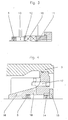
- FIG. 1 shows in section a turbomachine (1) designed as a double-flow centrifugal pump, the shaft (2) of which penetrates the housing (3) on both sides.
- the shaft (2) is sealed by means of stuffing boxes (4) - other common sealing elements are can also be used - in which a shaft sealing ring (5) is used instead of a packing ring or shut-off element closest to the inside of the housing.
- the free end of its sealing lip (6) faces the inside of the housing.
- the shaft sealing ring (5) is further followed by a locking ring (7) which is supplied with sealing fluid through a line (8) from the pressure chamber (9) of the turbomachine.
- the locking ring is followed by packing rings (10), which are pressed tightly against the shaft or the shaft protection sleeve attached to it by means of stuffing box goggles (11).
- FIG. 2 An enlarged representation of the shaft seal is shown in FIG. 2.
- the shaft sealing ring (5) is installed so that the free end of its sealing lip (6) faces the inside of the turbomachine.
- a locking ring (7) several, here two packing rings (10) are arranged downstream and are pressed tightly by gland packing (11).
- a ring (12) is used instead of a locking ring, which prevents the packing rings (10) from being pressed too far into the stuffing box space (13) by the stuffing box goggles (11) and thus the supply for the Barrier liquid can be blocked.
- the embodiment of a shaft seal shown in FIG. 4 uses only a single shaft sealing ring (14) for sealing to the outside instead of gland rings.
- An externally attached support ring (15) is used to secure the position of the shaft sealing ring (14).
- the shaft sealing rings (5, 14) are arranged inside a sealing housing (16), which in turn is inside of the turbomachine housing (3) is positioned as an independent component.
- the sealing liquid supply ensures the channels (17, 18).
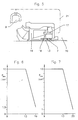
- FIG 5 shows schematically a section of the turbomachine, in particular the operative connection between the pressure chamber (9) and a conventional stuffing box. Only packing rings are arranged on both sides of the locking ring (7) for shaft sealing.
- FIG. 6 the pressure conditions within a stuffing box according to FIG. 5 are shown diagrams.
- the pressure profiles are plotted over the individual spaces of the shaft seal, in FIG. 6 the pressure profile from the pressure chamber (9) to the gland chamber (13) within the gland with the locking ring (7) arranged therein and further to the suction chamber (19).
- the pressure level in the stuffing box chamber (13) of the shaft seal is not determined by the assumed low pressure of approx. 1.5 bar in the suction chamber, but essentially by the pressure in the pressure chamber (9).
- Fig. 7 corresponds largely to the structure of FIG. 6, but with the difference that the pressure drop to the atmosphere side (20) is shown starting from the stuffing box space (13).
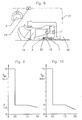
- FIG. 8 shows an illustration of the shaft seal according to the invention.
- a sealing or packing ring that is usually turned towards the inside of the pump has been replaced here by a shaft sealing ring (5) installed to some extent upside down.
- the pressure prevailing in the stuffing box chamber (13) can be reduced to the suction chamber (19) via the sealing lip of the shaft sealing ring (5) which lifts off the shaft.
- the free end (6) of the shaft sealing ring (5) deflects outwards, but the tension spring ring (22) acting on it only allows a limited opening and a defined throttle gap is thus formed. This is easily possible by appropriate design of the sealing lips or the lip material used and the tension spring used.
- the shaft sealing ring (5) is thus used contrary to its actual purpose.
- a throttle (23) inserted into the connecting line (21) ensures that the shaft seal is only loaded with a very low pressure. This also keeps possible fluid losses, the friction of the outer sealing elements and the wear and tear within limits.
- FIGS. 9 and 10 show the pressure conditions occurring within the shaft seal in a manner corresponding to FIGS. 6 and 7.
- Fig. 9 it can be seen that as a result of a throttle (23) installed in the connecting line (21) within the stuffing box space (13) of the shaft seal, there is only a pressure of about 2 bar.
- the shaft sealing ring (5) which acts as a second throttle and has a degressive loss characteristic, only a pressure difference of approx. 0.5 bar has to be reduced compared to the suction chamber. A pressure of 1.5 bar within the suction space is assumed.
- FIG. 10 only a pressure of 1 bar has to be sealed off from the atmosphere side (20).
Landscapes
- Engineering & Computer Science (AREA)
- General Engineering & Computer Science (AREA)
- Mechanical Engineering (AREA)
- Structures Of Non-Positive Displacement Pumps (AREA)
- Sealing Devices (AREA)
Applications Claiming Priority (2)
| Application Number | Priority Date | Filing Date | Title |
|---|---|---|---|
| DE19883843429 DE3843429A1 (de) | 1988-12-23 | 1988-12-23 | Wellenabdichtung an stroemungsmaschinen |
| DE3843429 | 1988-12-23 |
Publications (2)
| Publication Number | Publication Date |
|---|---|
| EP0374713A2 true EP0374713A2 (fr) | 1990-06-27 |
| EP0374713A3 EP0374713A3 (fr) | 1990-08-08 |
Family
ID=6369969
Family Applications (1)
| Application Number | Title | Priority Date | Filing Date |
|---|---|---|---|
| EP89123014A Withdrawn EP0374713A3 (fr) | 1988-12-23 | 1989-12-13 | Graniture d'étanchéité d'arbre pour turbomachine |
Country Status (2)
| Country | Link |
|---|---|
| EP (1) | EP0374713A3 (fr) |
| DE (1) | DE3843429A1 (fr) |
Cited By (3)
| Publication number | Priority date | Publication date | Assignee | Title |
|---|---|---|---|---|
| EP0484582A1 (fr) * | 1989-05-03 | 1992-05-13 | SIHI GmbH & Co KG | Pompe centrifuge pour pomper des fluides chauds |
| WO1998023886A1 (fr) * | 1996-11-27 | 1998-06-04 | Alliedsignal, Inc. | Joint d'etancheite rotatif pour un turbocompresseur, a equilibrage des pressions. |
| WO2006135944A1 (fr) * | 2005-06-21 | 2006-12-28 | Erwin Kopp | Dispositif d'etancheite radial |
Family Cites Families (12)
| Publication number | Priority date | Publication date | Assignee | Title |
|---|---|---|---|---|
| US1737870A (en) * | 1924-06-05 | 1929-12-03 | Archibald S Telfer | Pump |
| GB434261A (en) * | 1934-01-13 | 1935-08-28 | British Thomson Houston Co Ltd | Improvements in and relating to centrifugal pumps |
| GB480524A (en) * | 1935-07-08 | 1938-02-23 | Richard James Spargo | Improvements in liquid seals for relatively rotating members |
| FR1033185A (fr) * | 1951-02-27 | 1953-07-08 | Perfectionnement aux moyens d'arrosage des paliers et des garnitures des pompes | |
| DE1037269B (de) * | 1954-02-22 | 1958-08-21 | Diebold & Cie S A | Wellendichtung fuer Kreiselpumpen zur Foerderung von schleifenden oder aggressiven Fluessigkeiten |
| DE1600502A1 (de) * | 1967-06-03 | 1970-01-29 | Krauss Maffei Ag | Vorrichtung zum Abdichten einer zumindest etwa senkrecht verlaufenden Wellendurchfuehrung |
| AT291777B (de) * | 1969-05-05 | 1971-07-26 | Vogel Pumpen | Wellendurchführung für Kreiselpumpen u.ähnl. Arbeitsmaschinen |
| SE332311B (fr) * | 1970-03-25 | 1971-02-01 | Kaelie Requlatorar Ab | |
| GB1389832A (en) * | 1971-03-18 | 1975-04-09 | Aeroquip Ltd | Seal assemblies |
| GB1311058A (en) * | 1971-12-14 | 1973-03-21 | Warwick Pump & Eng Co | Fluid sealing devices |
| FR2340490A1 (fr) * | 1976-02-04 | 1977-09-02 | Legoy Auguste | Dispositif d'etancheite pour machine rotative a fluide hydraulique |
| US4239422A (en) * | 1979-10-04 | 1980-12-16 | Conoco, Inc. | Flushing fluid for centrifugal pumps used in the pipelining of slurries |
-
1988
- 1988-12-23 DE DE19883843429 patent/DE3843429A1/de not_active Withdrawn
-
1989
- 1989-12-13 EP EP89123014A patent/EP0374713A3/fr not_active Withdrawn
Cited By (4)
| Publication number | Priority date | Publication date | Assignee | Title |
|---|---|---|---|---|
| EP0484582A1 (fr) * | 1989-05-03 | 1992-05-13 | SIHI GmbH & Co KG | Pompe centrifuge pour pomper des fluides chauds |
| WO1998023886A1 (fr) * | 1996-11-27 | 1998-06-04 | Alliedsignal, Inc. | Joint d'etancheite rotatif pour un turbocompresseur, a equilibrage des pressions. |
| US5890881A (en) * | 1996-11-27 | 1999-04-06 | Alliedsignal Inc. | Pressure balanced turbocharger rotating seal |
| WO2006135944A1 (fr) * | 2005-06-21 | 2006-12-28 | Erwin Kopp | Dispositif d'etancheite radial |
Also Published As
| Publication number | Publication date |
|---|---|
| DE3843429A1 (de) | 1990-06-28 |
| EP0374713A3 (fr) | 1990-08-08 |
Similar Documents
| Publication | Publication Date | Title |
|---|---|---|
| EP0235568B1 (fr) | Dispositif de joint racleur à deux lèvres | |
| DE3620539C2 (fr) | ||
| DE2441520A1 (de) | Wellendichtung fuer schraubenrotorverdichter | |
| EP0316751A1 (fr) | Dispositif d'étanchéité | |
| DE69921404T2 (de) | Dichtungsanordnung mit automatischer Spieleinstellung | |
| DE3404520A1 (de) | Kolben- bzw. plungerpumpe | |
| DE3537822C2 (fr) | ||
| DE2511306A1 (de) | Schlauchabsperrventil mit einem mit laengsrippen versehenen einsatzstueck | |
| DE2403319A1 (de) | Zahnradmaschine | |
| EP0321770B1 (fr) | Dispositif d'étanchéité | |
| DE3045215A1 (de) | Klappe | |
| DE2504089C3 (de) | Verschluß zur Verriegelung eines Deckels | |
| DE3141512A1 (de) | Gleit- und/oder gegenring einer gleitringdichtung | |
| DE69005217T2 (de) | Anlage zum Verringern von Radialbelastung und diese umfassende Gleitlager und Schraubenverdichter. | |
| EP1994315B1 (fr) | Joint a levre radial | |
| EP1505307A1 (fr) | Garniture d'étanchéité pour palier radial à roulement | |
| DE3843429A1 (de) | Wellenabdichtung an stroemungsmaschinen | |
| EP0014906B1 (fr) | Joint d'étanchéité pour tiges ou tiges-poussoirs | |
| DE2844906C2 (de) | Dichtring, insbesondere für hydraulisch betätigte Zylinderkolben oder Kolbenstangen | |
| EP0588258B1 (fr) | Carter d'etage en plusieurs parties | |
| DE2744172A1 (de) | Wellendichtung, insbesondere fuer grosse verdichterwellen | |
| EP0102441B1 (fr) | Appareil à pompe ou à moteur ayant des dispositifs annulaires coniques | |
| DE2630499C2 (de) | Dichtungsanordnung für einen in eine Deckelaufnahme eingesetzten Deckel | |
| DE7830716U1 (de) | Dichtring, insbesondere für hydraulisch betätigte Zylinderkolben oder Kolbenstangen | |
| AT236179B (de) | Absperrvorrichtung |
Legal Events
| Date | Code | Title | Description |
|---|---|---|---|
| PUAI | Public reference made under article 153(3) epc to a published international application that has entered the european phase |
Free format text: ORIGINAL CODE: 0009012 |
|
| PUAL | Search report despatched |
Free format text: ORIGINAL CODE: 0009013 |
|
| AK | Designated contracting states |
Kind code of ref document: A2 Designated state(s): DE FR GB IT NL |
|
| AK | Designated contracting states |
Kind code of ref document: A3 Designated state(s): DE FR GB IT NL |
|
| STAA | Information on the status of an ep patent application or granted ep patent |
Free format text: STATUS: THE APPLICATION HAS BEEN WITHDRAWN |
|
| 18W | Application withdrawn |
Withdrawal date: 19910214 |